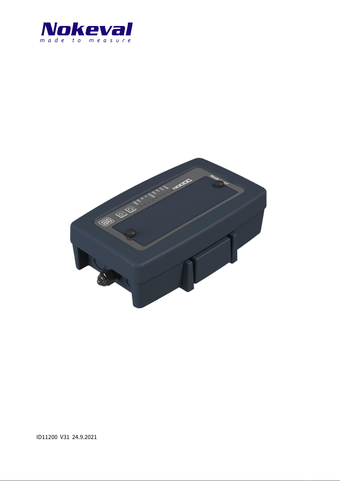
Nokeval Cell2-Sky-Link-RS485-LTE/LAN User manual

ID11200 V31 24.9.2021
Firmware versions 1.0-1.0
Cell2-Sky-Link-RS485-LTE/LAN
User Manual

2
Table of contents
Introduction ....................................................................................................................................................4
Serial interface ............................................................................................................................................4
Sky radio......................................................................................................................................................4
Installation ......................................................................................................................................................5
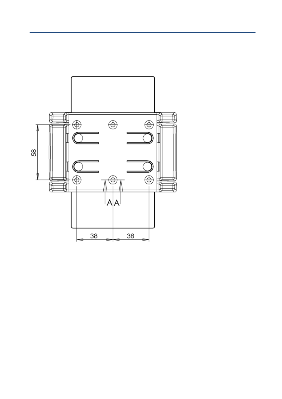
Wall holder ..................................................................................................................................................5
Installation location....................................................................................................................................5
Connections ................................................................................................................................................6
Power supply & serial RS-485 connector ...............................................................................................6
Micro-SIM.................................................................................................................................................7
Cellular network LED...............................................................................................................................7
RS-485......................................................................................................................................................7
RS-485 bus information ..........................................................................................................................7
Backup battery case and POL connector...............................................................................................8
Configuring the device....................................................................................................................................9
Connection settings ................................................................................................................................9
Programming connector.........................................................................................................................9
Conf menu ...................................................................................................................................................9
Time settings...........................................................................................................................................9
Serial settings..........................................................................................................................................9
Network .................................................................................................................................................16
Nokeval Sky settings.............................................................................................................................17
Buzzer ....................................................................................................................................................18
Info.........................................................................................................................................................19
Mon menu..................................................................................................................................................19
Cal menu....................................................................................................................................................20
Usage.............................................................................................................................................................21
LEDs ...........................................................................................................................................................21
2G/4G .....................................................................................................................................................21
LAN.........................................................................................................................................................21
Uplink.....................................................................................................................................................21
Mem .......................................................................................................................................................21
Sky .........................................................................................................................................................22
RS485.....................................................................................................................................................22
FOTA.......................................................................................................................................................22
Batt ........................................................................................................................................................22
Power.....................................................................................................................................................22

3
Multifunction button ...........................................................................................................................22
Status information....................................................................................................................................22
Maintenance..................................................................................................................................................24
Cleaning.....................................................................................................................................................24
Service .......................................................................................................................................................24
Troubleshooting............................................................................................................................................25
Specifications................................................................................................................................................26
Environment..........................................................................................................................................26
Measurements.......................................................................................................................................26
User interface ........................................................................................................................................26
Internal memory for buffered results...................................................................................................26
Backup batteries ...................................................................................................................................26
433.92 MHz radio transceiver (Sky) ......................................................................................................26
Network connection, depending on the device type...........................................................................26
Power supply.........................................................................................................................................26
Other......................................................................................................................................................27
Cloud connection..................................................................................................................................27
Warnings........................................................................................................................................................28
Open-Source Software Notice......................................................................................................................29
Trademarks ...................................................................................................................................................32
Manufacturer.................................................................................................................................................32

4
Introduction
Cell2-Sky-Link-RS485-LTE and Cell2-Sky-Link-RS485-LAN are base stations for Nokeval’s 433.92MHz
Sky-transmitters and are part of Nokeval Sky product families. They receive and buffer radio packets to
non-volatile memory and transmit them over cellular mobile data networks (LTE model) or local area
networks (LAN model) to Nokeval’s cloud data collections services, like Ovaport, thus enabling reliable
remote data acquisition from the field, straight to the cloud. The base station’s reliability is increased
by the backup batteries, which enable uninterrupted data acquisition also during external power
interruptions.
Serial interface
The base station can also be connected to standard Modbus RTU transmitters and to Nokeval
devices with SCL protocol using the integrated RS485 bus master.
Sky radio
Nokeval’s third generation Sky radio devices use the Semtech’s LoRa modulation technology on the
European license-free 433 MHz ISM band that allows unforeseen wireless range for battery powered
transmitters. The protocol used is defined by Nokeval, called Sky, which means that these devices are
not compatible with the LoRaWAN infrastructure.
The modulation has some parameters to define its operation. With the “maximal” settings, a very long
range can be reached, but at the expense of higher battery and radio band consumption. One radio
transmission can last approx. 2 seconds (compared to 20 ms of the Nokeval MTR series). This means
that the number of transmitters within the range must be limited to avoid collisions and to allow radio
time for each. It is not practical to use a short interval between transmissions; 10 to 30 minutes is the
recommended interval range.
When the maximal range is not necessary, the parameters should be adjusted for lower battery and
band consumption. All the devices within one network must share the parameters, because the
receiver can only listen with one set of parameters at a time. Consequently, the parameters must be
selected according to the most distant device. It is also possible to adjust the transmission power. The
devices that are closer to the receiver can use a lower power setting.
Before using these 433 MHz radio devices, make sure it is legal in your country.

5
Installation
Wall holder
Install the base station to a wall or some other suitable surface with the separate wall holder. See the
following dimensional drawing for the wall holder’s mounting hole distances. Use fastening accessories
suitable for the wall material, like plugs and screws. The screws need to have a countersunk head.
Installation location
Choose an installation location that is central in relation to the radio transmitters.
The base station must be installed vertically. The base station is splash waterproof, but the location
must be chosen so that the unit will not be exposed to water or hot steam. Please note that the AC
socket and the power supply are not splash waterproof.
The location must have LTE/GSM/GPRS network coverage for the LTE model. This can be verified before
the final installation steps by powering on the base station and checking the signal strength indicator
LEDs (see page 21). Installation location must have one free AC socket for the power supply.

6
Connections
Power supply & serial RS-485 connector
Inside the device, at the bottom right of the circuit board, is a four-pole spring cage / plug-in terminal
block connector. It is a combined power supply and serial data connector.
The table below describes the function of each connector pole.
Symbol
Description
+24VDC
Power supply positive connection, 18…28 VDC
GND
Power supply negative connection, RS-485 bus ground
D1
RS-485-bus D1 connection
D0
RS-485 bus D0 connection

7
Micro-SIM
Insert micro-sized SIM card with a PIN code request set to off.
Cellular network LED
•LTE Cat NB1/M1: LED lit continuously
•LTE Cat NB1/M1 roaming: LED flashes once per second
•eGPRS: LED flashes once every 2 second
•eGPRS roaming: LED flashes twice every 2 second
RS-485
RS-485 serial communication can be used to read results from external devices. The protocol can be
Modbus, Nokeval SCL or also ASCII protocol for Vaisala WXT500 series weather transmitter.
The RS-485 bus termination can be set with jumpers on the circuit board, as shown below. Extra
jumpers can be put at the places marked in gray. These do not affect the connection.
Off
AC termination
Failsafe biasing
AC termination & Failsafe biasing
This example picture illustrates how the base station can be connected to an RMD680 / RMD681
transmitter by sharing one 24 VDC power supply.
RS-485 bus information
RS-485 is a serial bus type commonly used in the industry. It is based on two data lines D0 and D1,
which are connected in parallel with all the devices connected to RS-485 bus and D0 and D1 pins. To
even up the electric potential between different devices, a third wire is also needed. In the above
example picture the blue ground wire evens the potential differences between the devices. Branches in
the bus should be avoided, in other words the bus cabling should circulate through all the devices
without branches. The maximum recommended length of the bus is 1 km. The cable should be twisted
pair and the wire diameter should be at least 0.5 mm.
To ensure EMC compliance the RS-485 bus cable should no more than 30 meters long.
The bus is bidirectional. Only one device at a time can send data, during which other devices listen.
Only one device connected to the bus is set as a master, in other words as a chairman, which starts all
conversations on the bus. Other devices are slaves and they only answer to queries of the master. Each
device connected to the bus has its unique bus address, which the master device uses to direct its
commands to a specific device.

8
The base station functions as an RS-485 bus-master and queries the measurement data from other
devices on the bus. In a typical application, such as the one presented in the diagram above, the base
station regularly queries the RMD680 / RMD681 transmitter’s measurement data and sends it to the
Ovaport server.
Backup battery case and POL connector
The battery cover can be opened by removing the two screws on the cover of the device. The screws
indicated by the arrows are shown in the picture below. The device uses two D-size heavy-duty alkaline
batteries. There is also a Meku POL configuration connector inside the battery case. See "Configuring
the device" in the next section of the manual. The location of the POL connector is marked with a circle
in the figure below.

9
Configuring the device
There is usually no need to configure the device since most of the settings are already at their best
defaults. However, if you want to see what kind of settings there are or edit settings, use MekuWin
program and DCS772 (USB-POL converter). You can download MekuWin from Nokeval’s web site
www.nokeval.com for free.
Connection settings
Communication settings for configuration:
•baud rate 9600
•protocol SCL
•address 0
Programming connector
The device has a 3PIN POL programming connector under the backup battery compartment lid.
Remove the battery compartment lid to access the programming connector. Use POL-3PIN adaptor to
connect the DCS772 to the device. The 3PIN POL programming connector can be connected in both
ways.
Conf menu
Time settings
The device can forward packets only if it has a time set. It receives time information from internet, so
you do not need normally to use this manual setting.
Serial settings
The device can retrieve measurement results with the following serial communication protocols:
Modbus RTU, Nokeval SCL or Vaisala's WXT5x0 ascii protocol.
Basic settings for serial communication

10
Protocol
•Modbus
•WXT5x0 Ascii
•SCL
Baud rate
300, 600, 1200, 2400, 4800, 9600, 19200, 38400, 57600, 115200, 125000, 230400.
Bits
•8N1 (8 data bits, No Parity, 1 stop bit)
•8N2 (8 data bits, No Parity, 2 stop bit)
•8E1 (8 data bits, Even Parity, 1 stop bit)
•8O1 (8 data bits, Odd Parity, 1 stop bit)
Timeout [s]
1 –5 s
After the command, the response is expected to receive from device in the timeout period. If the
time is exceeded and no response received, an error is set.
Query interval [das]
1 –29 das
Query interval time between queries. Presented in decaseconds (das, a unit of time equal to 10
seconds). For example, value 3 = 30 seconds.
Queries
1 - 64
The number of different queries. The maximum is 64. Each device that is being queried needs at
least one query and if the same device is queried for multiple information which is not in
subsequent registers or they have different data types, multiple queries are needed.
Virtual ID offset
0
A setting that shifts (sums) the value of all virtual IDs. Practical to move virtual IDs to a different
area if there are many gateways in the same destination with similar serial communication settings.
Overview
Displays the serial communication status for each query:
•Not used (Results setting zero)
•OK
•Incorrect settings - Conf settings are incorrect
•Limited - Only part of the sequential results is fetched, because virtual ID has overlapping with
some other query or “internal status” result.
•Blocked –The result is not fetched, because virtual ID has overlapping with some other query or
“internal status” result.

11
•Unrecognized data - Modbus reply is wrong type or wrong length.
•Timeout –No response was received from the device.
•Exception –Device returned error code.
•CRC error
•Unknown error
Overview views queries and replies status and the first result. For example, "OK 24.2", "Timeout",
CRC error", "Unrecognized data" and so on.
Query 1 –64
Settings for each selected query.
Modbus RTU
If Modbus is used, choose Modbus protocol and desired serial basic settings. Bits settings for Modbus is
usually 8E1.
Query 1 –64, submenus for each selected query.
MB Slave
1 - 247
Modbus device address.
Register type
•Input Register
•Holding Register
•Discrete input
•Coil status

12
•Nopsa radio data
Modbus command / register type (search info on this from the other device’s manual). Discrete
input and Coil status registers are bit data, and the result will be either 0 or 1. Nopsa radio data
reads data from specific Nokeval radio receivers, such as the FT20.
Register
Register address (search info on this from the other device’s manual).
Results
1 - 62
The number of subsequent results that can be read. The maximum is 62.
Data type
Data type when register type is Input Register or Holding Register (search info on this from the
other device’s manual).
•Sint 16-bit
•Uint 16-bit
•Sint 32-bit BE
•Uint 32-bit BE
•Sint 32-bit LE
•Uint 32-bit LE
•Float BE
•Float LE
•Bit field
Sint is signed integer, Uint is unsigned integer.
Float is 32-bits, single-precision floating-point number.
BE = Big-endian, first 16-bit word is most significant.
LE = Little-endian, first 16 bits word is least significant.
Bit field offset
0 - 15
The first readable bit of the register when register Data type is Bit Field (starting from the least
significant bit).
The number of readable subsequent bits is set in the Results menu. The direction to read starts
from the least significant bit and continues to the next register. Data Type Bit field gives result of 0
or 1.
Divider
Off, 10 –1000000.
When needed, divides the result with decades (moves comma left). Usable with integers.
Additional calculation (Multiplier, Offset)
This allows you to multiply and/or addition the value.

13
Virtual ID
The Virtual ID of the first result of the Modbus query. In the Ovaport Measuring points settings the
"device address" and this virtual ID must match each other.
Status
•Not used (Results setting zero)
•OK
•Incorrect settings - Conf settings are incorrect
•Limited - Only part of the sequential results is fetched, because virtual ID has overlapping with
some other Modbus query or “internal status” result.
•Blocked –The result is not fetched, because virtual ID has overlapping with some other Modbus
query or “internal status” result.
•Unrecognized data - Modbus reply is wrong type or wrong length.
•Timeout - No response was received from the device.
•Exception –Modbus device returned error code.
•CRC error
•Unknown error
Overview views Modbus queries and replies status and the first result. For example, "OK 24.2",
"Timeout", CRC error", "Unrecognized data" and so on.
Examples of the Modbus settings
The following examples are in the test connection where Nokeval FT20, TTM20X, Eurotherm 2216e and
Nokeval RMD681 were connected to Modbus line and where Virtual IDs were set as follows.
The device / reading
Slave Address
Virtual IDs
Internal measurements
0…2
FT20
4
3…5
TTM20X
2
6
Eurotherm 2216e
1
7
RMD681
3
8…15
Config / Modbus
Baud rate
19200
Bits
8E1
Timeout[s]
1
Query interval[das]
3
Queries
4
Overview
->
Query 1
->
Query 2
->
Query 3
->
Query 4
->
Example of the Modbus settings for RMD681
Config / Modbus / Query 1
Slave
3
Register Type
Input Register
Register
0
Results
8
Data type
Float LE

14
Divider
-
Virtual ID
8
Status
OK 25.2
Example of the Modbus settings for FT20
Config / Modbus / Query 2
Slave
4
Register Type
Input Register
Register
1000
Results
3
Data type
Sint 16-bit
Divider
10
Virtual ID
3
Status
OK 15.3
Example of the Modbus settings for TTM20X
Config / Modbus / Query 3
Slave
2
Register Type
Holding Register
Register
0
Results
1
Data type
Sint 32-bit LE
Divider
10
Virtual ID
6
Status
OK 26.8
Example of the Modbus settings for Eurotherm 2216e
Config / Modbus / Query 4
Slave
1
Register Type
Input Register
Register
1
Results
1
Data type
Sint 16-bit
Divider
Off
Virtual ID
7
Status
OK 28.0
WXT5x0 Ascii
ASCII protocol for Vaisala WXT500 series weather transmitter.

15
Set the serial communication settings and number of queries. For each query, set the device
address and the desired parameter.
SCL
Nokeval SCL protocol.
Set the serial communication settings and number of queries. SCL bits is usually 8N1.
Query 1 –64, submenus for each selected query.
SCL address
0 –123. Device address.
Type
•Analog
•Digital
•Nopsa radio data
Analog: Reads measurement results using the MEA command.
Digital: Reads digital data using the DI command. The result is either 0 or 1.
Nopsa radio data: Reads data from specific Nokeval radio receivers, such as the FT20.
Channel
1 –64. The channel on the device being read.
Results
1 –8. The number of subsequent results that can be read.
Virtual ID
The Virtual ID of the first result of the SCL query. In the Ovaport Measuring points settings the
"device address" and this virtual ID must match each other.
Status
•Not used (Results setting zero)
•OK

16
•Incorrect settings - Conf settings are incorrect
•Limited - Only part of the sequential results is fetched, because virtual ID has overlapping with
some other SCL query or “internal status” result.
•Blocked –The result is not fetched, because virtual ID has overlapping with some other SCL
query or “internal status” result.
•Unrecognized data - SCL reply is wrong type or wrong length.
•Timeout - No response was received from the device.
•Exception –SCL device returned error code.
•CRC error
•Unknown error
Overview views SCL queries and replies status and the first result. For example, "OK 24.2",
"Timeout", CRC error", "Unrecognized data" and so on.
Network
Ovalog address and Ovalog port
The address and TCP port of the server to which the measurement results are sent.
Mobile network
APN: Cellular network access point name for internet connection. Can usually left blank.
Allow roaming: Set if it is necessary to connect to visitor networks.
Select primary operator: Selecting the primary operator might speed up the connection
establishment. MCC and MNC numeric codes are entered sequentially without spaces in the
Operator MCC-MNC code field.
Radio Access Tech: Select radio technologies , LTE Cat M1, LTE Cat NB1 and eGPRS, in order of
priority:
M1-NB1-2G
M1-2G-NB1
M1-NB1
M1-2G
M1
NB1-M1-2G
NB1-2G-M1
NB1-M1
NB1-2G
NB1

17
2G-M1-NB1
2G-NB1-M1
2G-M1
2G-NB1
2G
LTE M1/NB1 Bands: B3 (1800 MHz), B8 (900 MHz), B20 (800 MHz) and B28 (700 MHz).
LAN settings
DHCP: Dynamic Host Configuration Protocol (default on).
If DHCP is disabled, lines will appear where the IP address, subnet mask, gateway and DNS
server addresses can be set.
Firmware server
These settings must be as shown in the image above.
Nokeval Sky settings
Network
0..255.
The network address that must be the same for all devices on the same network.
Effort
1..7, Custom.
Small value:
+ Less power consumption.
+ Faster data rate.
- Shorter radio range.
Large value:
- More power consumption
- Slower data rate
+ Longer radio range.
Custom: Expert settings for frequency, bandwidth and spreading factor.
Power

18
0..10 dBm.
Output power range.
Channel
1..7. Disabled if effort “custom” is selected.
The frequency channels are spaced at 200 kHz. At Efforts below 7, two adjacent channels may
interfere.
Channel
Center frequency MHz
1
433.3
2
433.5
3
433.7
4
433.9
5
434.1
6
434.3
7
434.5
Auth. key
Key for Message Integrity Check and data encryption.
Enable beacon
Enable beacon for coverage mapping. Default Off.
Relay RX margin
Received signal margin can be stored in the buffer as its own channel. The reading should be a
positive value. If the reading is close to zero, the strength of the received signal is at the
reception limits.
RX margin channel
Select channel for the received signal margin. Default 59.
Relay batt level
Battery level can be stored in the buffer as its own data channel. Utility data packet that
includes battery information is a separate data packet than the measuring data packet.
Therefore, it arrives at the receiver at a different time and less frequently.
Batt level channel
Select channel for the battery level. Default 58.
Buzzer
Enable buzzer. Pressing the button causes a beep sound.
Battery alarm. If turned on, low battery voltage will also cause a beep.

19
Info
Info menu items are not configurable. They display various information about the device.
Mon menu
The monitor menu generally shows the status of the device and is mainly for manufacturer use.
Many menu items purposes are clear by name, and most of them are not explained in this
manual.

20
Buffer memory: Buff1, Buff2, Buff3 and Flash sectors:
If data arrives to the gateway faster than it can be send to the cloud, it stores the data in a buffer
memory.
First, the data passes through the device's RAM memories Buff1, Buff2 and Buff3. Data from memory
Buff3 is sent to cloud. 0% means empty, 100% means full. If Buff3 and Buff2 become full, the device will
start storing data of Buff2 to flash memory. One sector at a time.
The size of one flash sector corresponds to the size of one buff2 or buff3. "Flash tot. Sectors" indicates
the total number of sectors available and "Flash used sectors" indicates how many of them have been
used to store data.
Cal menu
The calibration menu settings are only for manufacturer use, and they are not explained in this manual.
Table of contents
Other Nokeval Accessories manuals
Popular Accessories manuals by other brands

Dini Argeo
Dini Argeo 3590EXT Series user manual

Manitowoc
Manitowoc RF1200W user manual

Leviton
Leviton IPP15-1L installation instructions

Atlantic Ultraviolet
Atlantic Ultraviolet Sanidyne PREMIUM owner's manual

ROSE DISPLAYS
ROSE DISPLAYS ANOCONNECTOR WITH ANOGOTCHA manual

Wulian
Wulian WL-ZSKMNPW-M3131-02 user manual