INTRODUCTION
RCS770 s a general-purpose ser al converter equ pped w th a USB port, RS-232 port and two RS-485 ports.
Convers on can be done n all d rect ons. Alternat vely, th s converter can act as a RS-485 repeater allow ng
more RS-485 dev ces to be used, s nce one bus can normally hold 32 dev ces. The two RS-485 ports can be
conf gured to act as a s ngle full-duplex RS-422 port or a four-w re RS-485 port.
USB, RS-232 and RS-485 sect ons are galvan cally solated from each other, wh ch w ll el m nate ground
loops and g ve more tolerance aga nst d sturbances and overvoltages. However, the two RS-485 buses are
not solated from each other.
If RCS770 s connected to a computer v a USB, t creates a v rtual ser al port that can be used just l ke an
ord nary port. Every converter has an nd v dual ser al number, and the converter w ll reta n the same COM
port number even f plugged nto a d fferent USB port on the same computer. Th s ncreases rel ab l ty.
RCS770 s able to pass var ous ser al protocols, nclud ng Nokeval SCL, Modbus ASCII, Modbus RTU, and
HART. The RS-485 d rect on s changed automat cally, no handshake l nes are requ red.
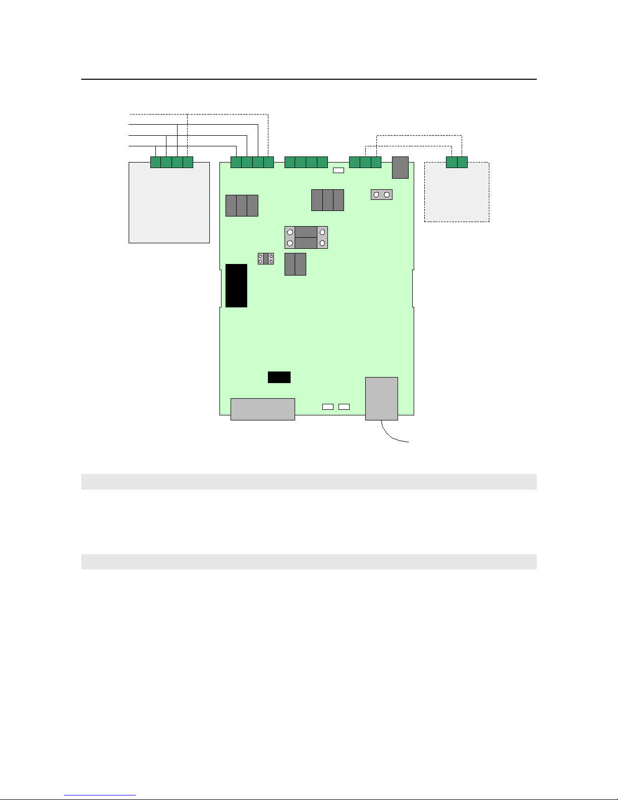
RS-485 bus s attached v a screw term nals, avo d ng the need to make solder jo nts on f eld.
SPECIFICATIONS
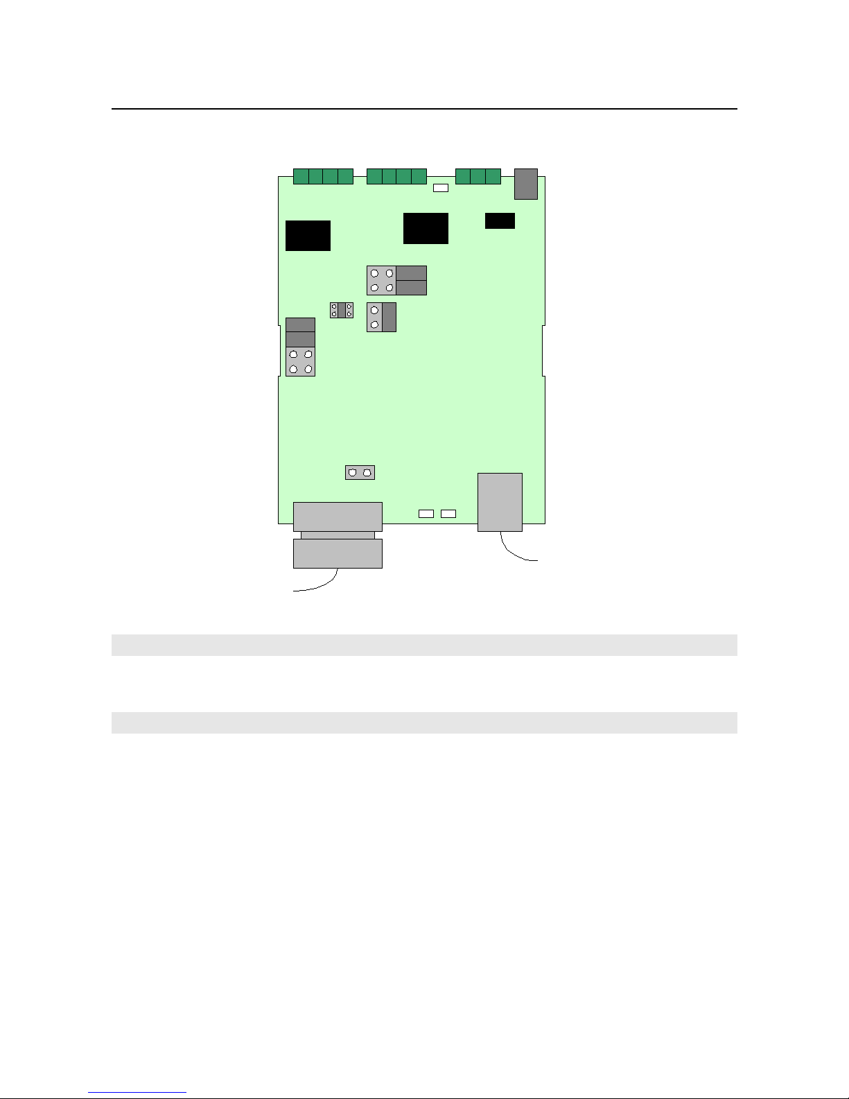
USB port
Vers on: USB 1.1 or 2.0
Interface ch p: FTDI FT232R
Power consumpt on: < 200 mA
Connector: USB-B (A-B cable ncluded)
RS-485 ports
Baud rates 300…230400 b t/s, except
as a repeater 1200…
115200.
Data b ts 5…8
Par ty All supported
Stop b ts 1, 1.5 or 2 on USB, 1 on
RS-232
Bus length 1000 m max
Dev ces on bus max 32 standard dev ces or
128 1/4 load dev ces
Load 1/4 load (128 dev ces of
th s k nd can ex st on the
same bus)
Transm tter enable Automat c
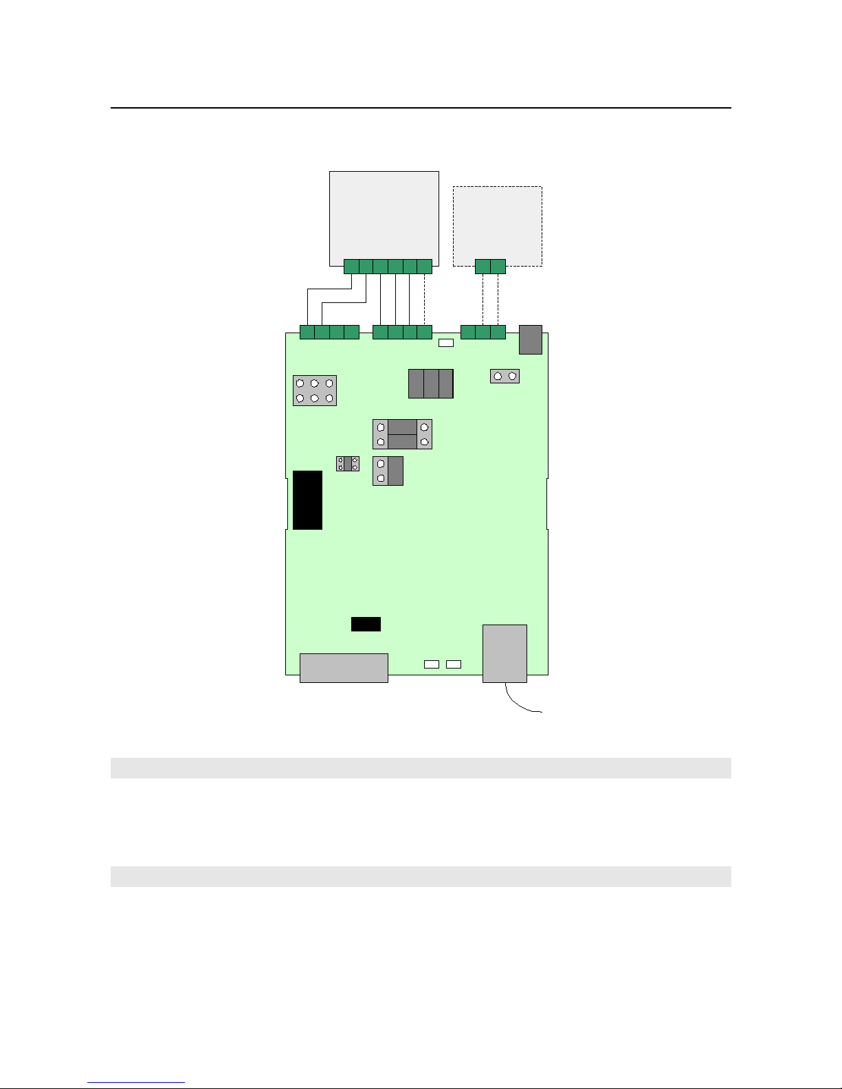
RS-232 port
Connector: D9 male (DTE) (null modem
cable for PC ncluded)
Baud rates: 1200, 2400, 4800, 9600,
19200, 38400, 57600,
115200
Handshake l nes: Not controllable, l nked
nternally
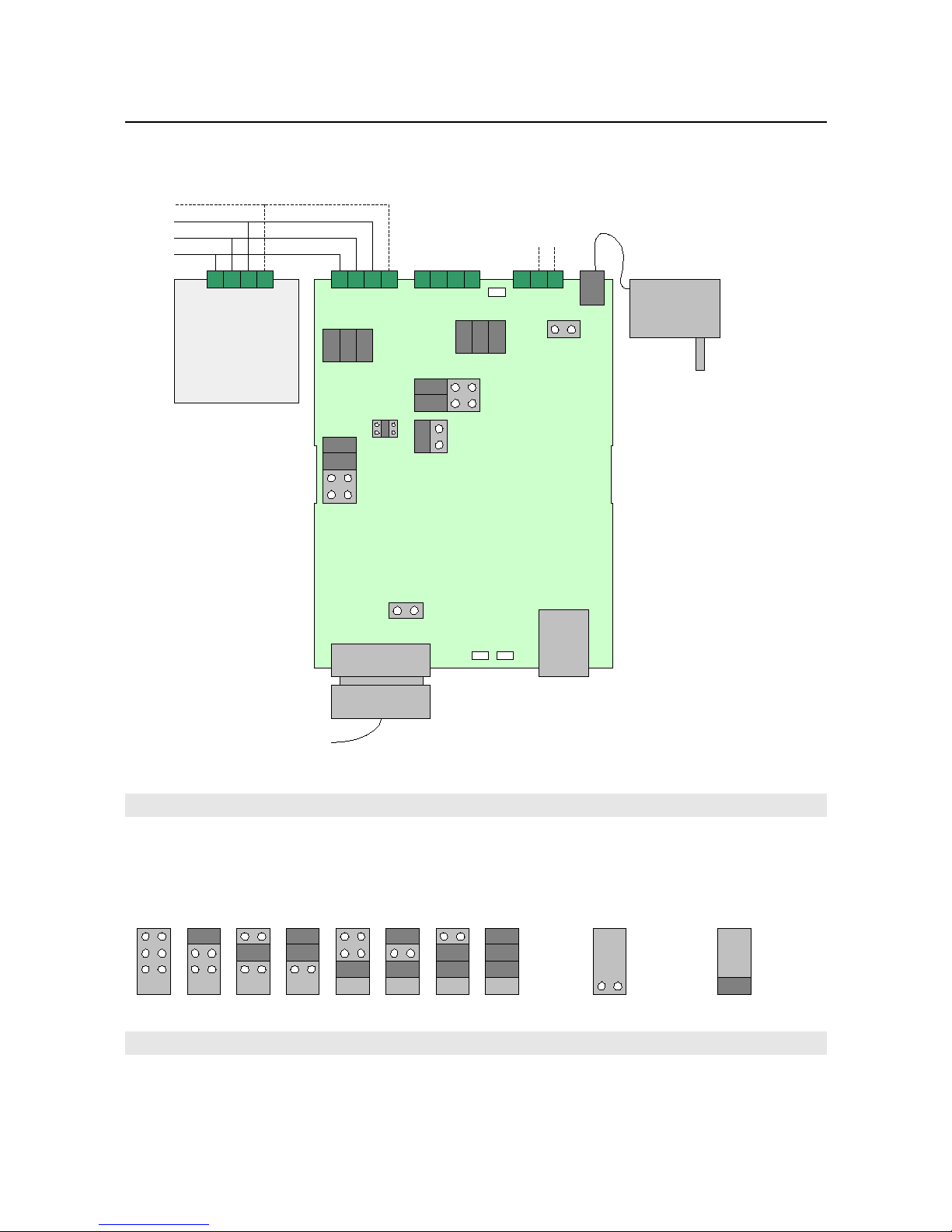
External po er supply
Note: external power supply s not necessary when
the USB s used.
Voltage: 8…28 VDC
Current: <200 mA
General
D mens ons: 70x85x60 mm + connectors
Oper. temperature: -30...60 °C
Galvan c solat on: Yes, 2kV AC/DC
EMC
EMC mmun ty EN 61326
EMC em ss ons EN 61326 class B
2