manuals.online logo
Brands
  1. Home
  2. •
  3. Brands
  4. •
  5. LDT
  6. •
  7. Media Converter
  8. •
  9. LDT TT-DEC Series User manual

LDT TT-DEC Series User manual

L
ittfinski
D
aten
T
echnik (
LDT
)
Multi-Digital
Assembly List:
Pos.
Qty.
Component
Remark
Ref.
Done
1 1 Printed circuit board
2 1 Resistor 10Ohm brown-black-black-gold R1
3 1 Resistor 360 Ohm orange-blue-black-black R2
4 1 Resistor 820 Ohm gray-red-black-black R3
5 4 Resistors1,5KOhm brown-green-black-brown R4... R7
6 1 Resistor 3,6KOhm orange-blue-black-brown R8
7 5 Resistors4,3KOhm yellow-orange-black-brown R9... R13
8 1 Resistor 4,7KOhm yellow-violet-black-brown R14
9 3 Resistors10KOhm brown-black-black-red R15 ... R17
10 1 Potentiometer 100Ohm marking: 100 ... P1
11 1 Potentiometer 2,5K Ohm marking: 2K5 ... P2
12 10 Diodes1N4003 attendtopolarity! D1... D10
13 1 Rectifier attendtopolarity! GL1
14 1 IC-Socket 28poles attendtopolarity! IC1
15 1 IC-Socket 16poles attendtopolarity! IC2
16 1 IC-Socket 8poles attendtopolarity! IC5
17 1 IC: 817 attendtopolarity! IC6
18 1 Resonator 12MHz CR1
19 1 PushButton S1
20 1 Capacitor 10nF 10nF = 103 C5
21 5 Capacitor 100nF 100nF=104 C6... C10
22 1 Electrolyticcap. 100uF/25V attend topolarity! C4
23 1 Electrolyticcap. 220uF/35V attend topolarity! C3
24 2 Electrolyticcap. 470uF/35V attend topolarity! C1, C2
25 1 Multi-FuseR090 MF1
26 1 Transistor BC557 attend topolarity! T1
27 2 TransistorsBC337 attendtopolarity! T2, T3
28 1 LEDgreenplus dist.- spacer attend to polarity! LED1
29 1 LEDyellowplusdist.-spacer attendtopolarity! LED2
30 1 LEDredplusdist.-spacer attendtopolarity! LED3
31 1 Pin-Bar 5poles JP1
32 1 Pin-Bar 6poles ST4
33 2 PhillipsScrewsM3x6 for assy. of IC3andIC4
34 2 SilikonInsulators for assy. of IC3 and IC4
35 2 IsolatingBushings for assy. of IC3andIC4
36 1 Heat Sink for assy. of IC3andIC4
37 1 IC:7805 assemblyon coolingbody IC3
38 1 IC: LM317 assemblyon coolingbody IC4
39 3 Clamps3poles buildblocsbeforeassy. KL1... KL3
40 1 Clamp2poles buildblocbeforeassy. KL4
41 1 Clamp2poles KL5
42 1 IC: ATMEGA8 attendtopolarity! IC1
43 1 IC: L293 attendtopolarity! IC2
44 1 IC: 6N137 attendtopolarity! IC5
45 Final Control
TurnTable-Decoder (TT-DEC)
from the Digital-Professional-Series !
TT-DEC-B
Part-No.:
010501
>>
kit
<<
For the digital control of Fleischmann-, Roco- and
Märklin-turntables.
Suitable for the digital formats Märklin-Motorola and DCC
⇒
For Fleischmann turntables: 6052, 6152, 6154, 6651, 9152, 6680
(each with and without “C”) and 6652 (with 3-rail conductor).
⇒
For Roco turntable: 35900.
⇒
For Märklin turntable: 7286.
⇒
There are no modification required at the turntables!
This product is not a toy! Not suitable for children under 14 years of age! The kit contains small parts, which
should be kept away from children under 3! Improper use will imply danger of injuring due to sharp edges and
tips! Please store this instruction carefully.
Made in Europe by
Littfinski DatenTechnik (LDT)
Bühler electronic GmbH
Ulmenstraße 43
15370 Fredersdorf / Germany
Phone: +49 (0) 33439 / 867-0
Internet: www.ldt-infocenter.com
Subject to technical changes and errors. 06/2019 by LDT
Märklin, Fleischmann and Motorola are registered trade marks.
Assembly Instruction
Introduction:
You have purchased a kit for your model railway supplied within the assortment of
Littfinski DatenTechnik (LDT). These kits are of high quality and easy to assemble.
We are wishing you having a good time for assembling and application of this
product!
General:
Tools required for the assembly
Please assure that the following tools are available:
•a small side cutter
•a mini soldering iron with a small tip
•solder tin (if possible 0.5mm diameter)
Safety Instructions
•All electrical and electronic components included in this kit shall be used on low voltage
only by using a tested and approved voltage transducer (transformer). All components
are sensitive to heat. During soldering the heat shall be applied for a very short period
only.
•The soldering iron develops a heat up to 400°C. Please keep continual attention to this
tool. Keep sufficient distance to combustible material. Use a heat resistant pad for this
work.
•This kit consist of small parts which can possibly be swallowed from children. Children
(especially under 3 years) shall not participate on the assembly without supervision.
Set-Up:
For the board assembly please follow exact the sequence of the below assembly list.
Cross each line off as done after completing the insertion and the soldering of the
respective part.
For the diodes please keep special attention the correct polarity (marked line for the
cathode).
Please attend to the polarity mark “+” of the rectifier GL1. Some manufacturer are
marking the +-side additional with an extended connection wire. If the rectifier contains a
flat side this side has to correspond to the marking on the pc-board.
With reason to different makes of electrolytic capacitors you will find different markings
of the polarity. Some are marked with "+" and some are marked with "-". Each capacitor
has to be assembled to the board that the marking on the capacitor is in correspondence
with the marking on the TT-DEC pc-board.
The three transistorsT1, T2 and T3 (BC XX7) have to be assembled with attention to
the flat side of the transistor.
Light emitting diodes have to be assembled that the long connection wire of the diode
corresponds to the mark "+" on the pc-board. Before assembly please slip one distance
spacer each onto the connection wires.
The voltage regulators IC3 (7805) and IC4 (LM317) shall be assembled to the heat
sink in accordance to the below illustration 1 and 2with insulator, insulator-bushing
and screw. Then insert the completed assembly into the bores of the pc-board and solder
them.
Integrated circuits (IC`s) are either marked with a half round notch on one end or a
printed point for the correct mounting position. Push the IC`s into the correct socket or
directly into the pc-board (IC6) assuring that the notch or the printed point is
corresponding to the half-rounded marking on the pc-board.
Additionally please attend to the sensitivity of the IC`s to electrostatic discharge which
can destroy the component. Before touching those components please discharge
yourself by contacting an earthed metal (e.g. heater etc.) or work with an electrostatic-
protected pad.
Assembly of the voltage regulator IC3 and IC4:
The voltage regulators IC3 (7805) and IC4 (LM317) shall be assembled to the heat
sink in accordance to the below illustration 1 and 2with insulator, isulating-bushing
and screw.
Then insert the completed pre-assembly into the bores of the pc-board and solder
them.
Finally tighten the two screws and solder the heat sink and the two voltage regulators.
Kühlkörper
heat sink Isolator
insulator
Isolierbuchse
isolatingbushing
IC3 und IC4
IC3 and IC4
Schraube
screw
Kühlkörper
heat sink Isolator
insulator
Isolierbuchse
isolating bushing
IC3 und IC4
IC3 and IC4
Schraube
screw
illustration 1 illustration 2

This manual suits for next models

2

Other LDT Media Converter manuals

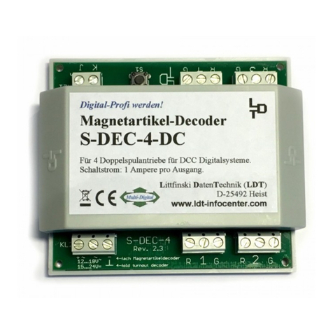
LDT S-DEC-4-DC-G User manual

LDT

LDT S-DEC-4-DC-G User manual

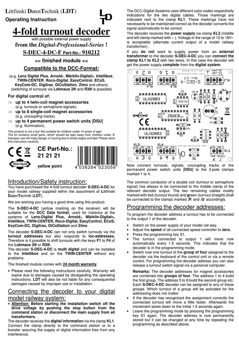
LDT Digital-Professional Series User manual
LDT

LDT Digital-Professional Series User manual

LDT LS-DEC Series User manual

LDT

LDT LS-DEC Series User manual
LDT LS-DEC-SNCF-F User manual

LDT

LDT LS-DEC-SNCF-F User manual
LDT QS-DEC-II-F User manual

LDT

LDT QS-DEC-II-F User manual
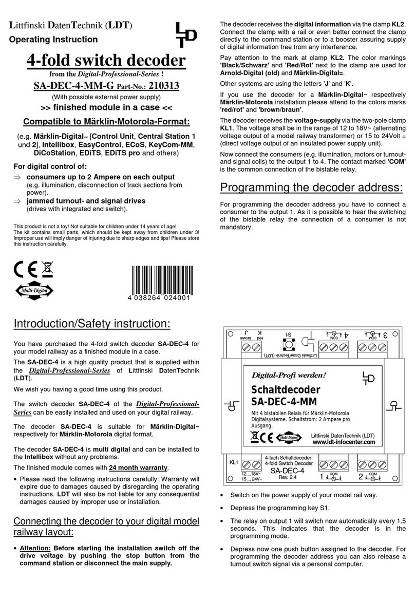
LDT SA-DEC-4-MM-G User manual

LDT

LDT SA-DEC-4-MM-G User manual
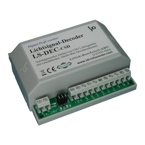
LDT LS-DEC-CSD-F User manual

LDT

LDT LS-DEC-CSD-F User manual
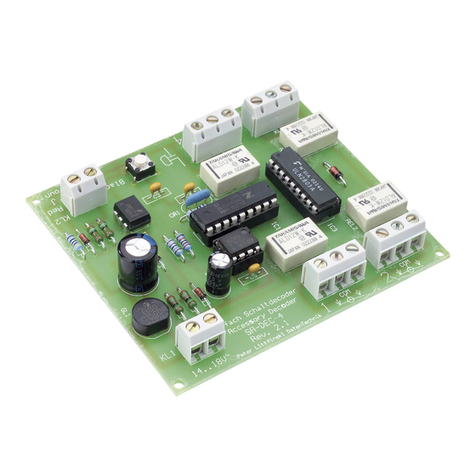
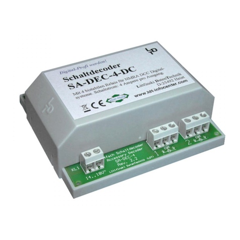
LDT SA-DEC-4 User manual

LDT

LDT SA-DEC-4 User manual
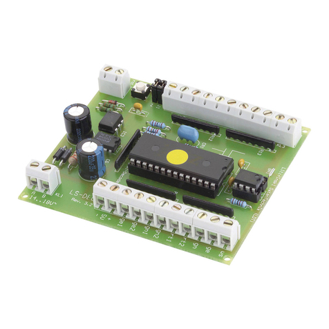
LDT LS-DEC-DB-F Technical manual

LDT

LDT LS-DEC-DB-F Technical manual
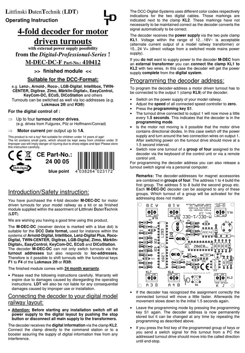
LDT M-DEC-DC-F User manual

LDT

LDT M-DEC-DC-F User manual
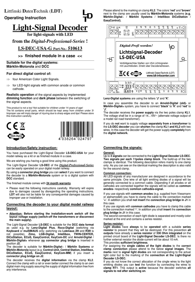
LDT LS-DEC-USA User manual

LDT

LDT LS-DEC-USA User manual

LDT SA-DEC-4-DC-B User manual

LDT

LDT SA-DEC-4-DC-B User manual
LDT LS-DEC-DR-F User manual

LDT

LDT LS-DEC-DR-F User manual
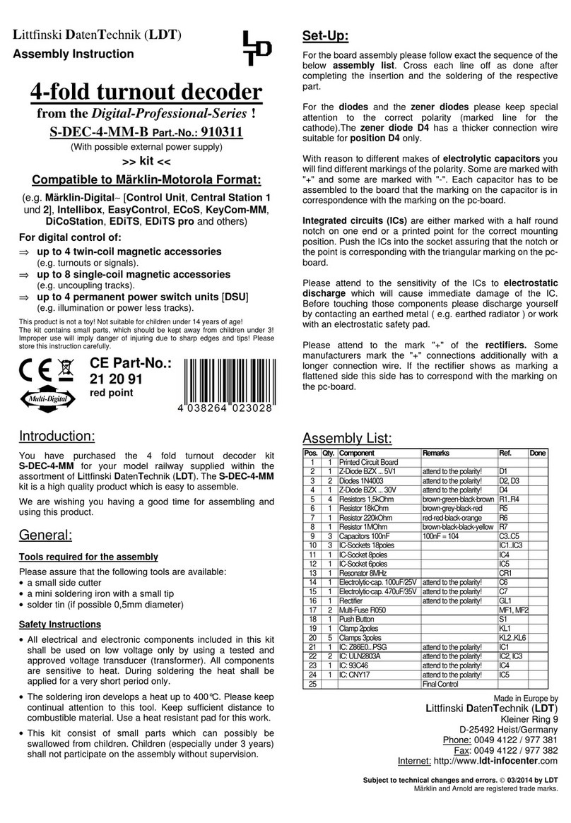
LDT S-DEC-4-MM-B User manual

LDT

LDT S-DEC-4-MM-B User manual
LDT Digital Professional Series Technical manual

LDT

LDT Digital Professional Series Technical manual

LDT Digital Professional Series User manual
LDT

LDT Digital Professional Series User manual

LDT TT-DEC-R User manual

LDT

LDT TT-DEC-R User manual

LDT Digital Professional Series User manual

LDT

LDT Digital Professional Series User manual

LDT Digital-Professional Series User manual

LDT

LDT Digital-Professional Series User manual

LDT S-DEC-4-DC-G User manual

LDT

LDT S-DEC-4-DC-G User manual

LDT LS-DEC-NS-F User manual

LDT

LDT LS-DEC-NS-F User manual

LDT SA-DEC-4-DC-G User manual

LDT

LDT SA-DEC-4-DC-G User manual

LDT Digital-Professional Series User manual

LDT

LDT Digital-Professional Series User manual

LDT M-DEC-MM-F User manual

LDT

LDT M-DEC-MM-F User manual

Popular Media Converter manuals by other brands

Neptune Technology E-CODER Quick install guide
Neptune Technology

Neptune Technology E-CODER Quick install guide

Lindy DVI + SPDIF to HDMI Converter 32559 user manual
Lindy

Lindy DVI + SPDIF to HDMI Converter 32559 user manual

Edimax GP-101SF Quick installation guide

Edimax

Edimax GP-101SF Quick installation guide

Allen-Bradley 4100-AEC Installation and setup manual
Allen-Bradley

Allen-Bradley 4100-AEC Installation and setup manual

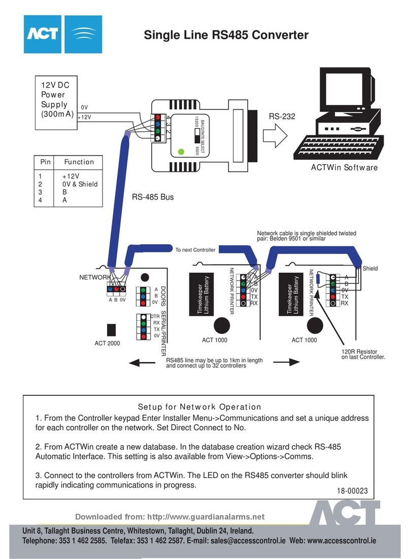
ACT SINGLE LINE RS485 CONVERTER manual
ACT

ACT SINGLE LINE RS485 CONVERTER manual

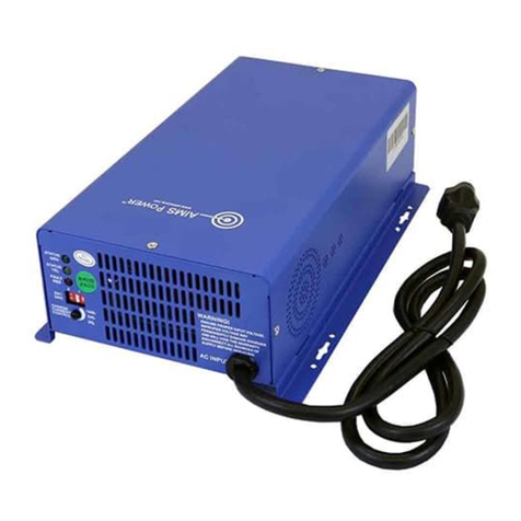
AIMS Power CON120AC36/48VDC user manual

AIMS Power

AIMS Power CON120AC36/48VDC user manual

SoundTraxx econami quick start guide

SoundTraxx

SoundTraxx econami quick start guide

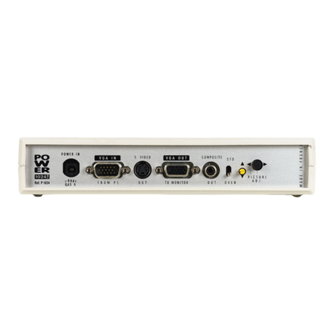
Analog way POWER 1024 user manual

Analog way

Analog way POWER 1024 user manual

THOMSON MPC-ETN - QUICK Quick installation guide

THOMSON

THOMSON MPC-ETN - QUICK Quick installation guide

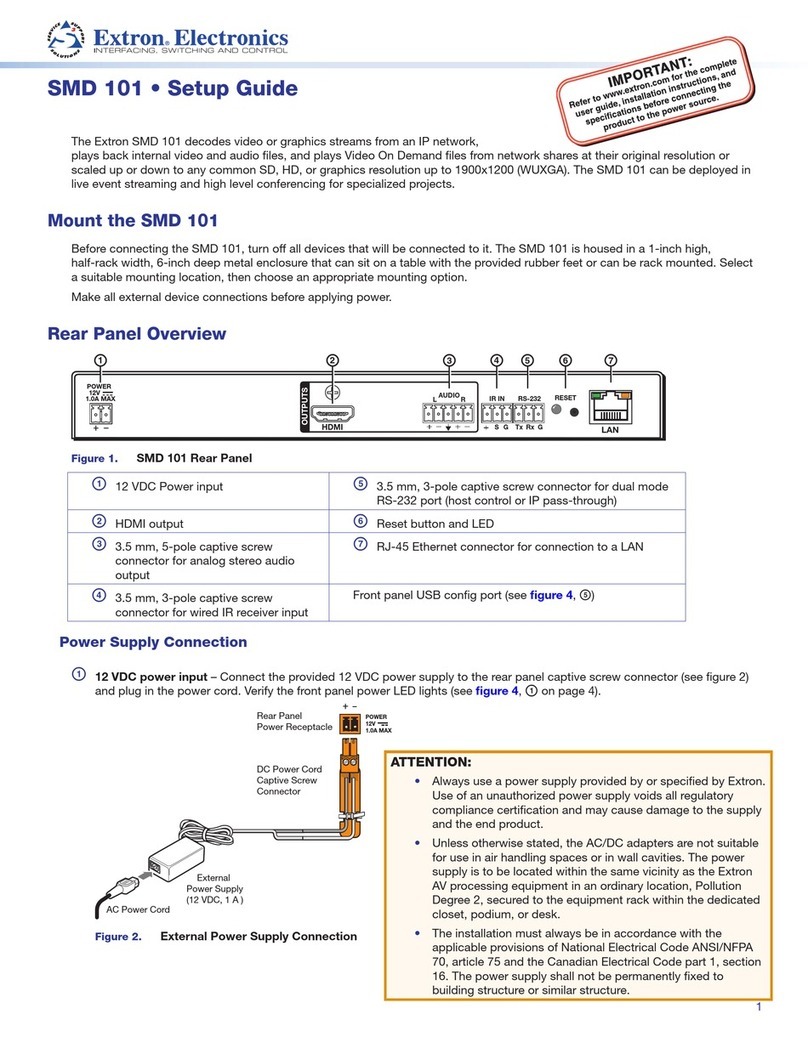
Extron electronics SMD 101 Setup guide

Extron electronics

Extron electronics SMD 101 Setup guide

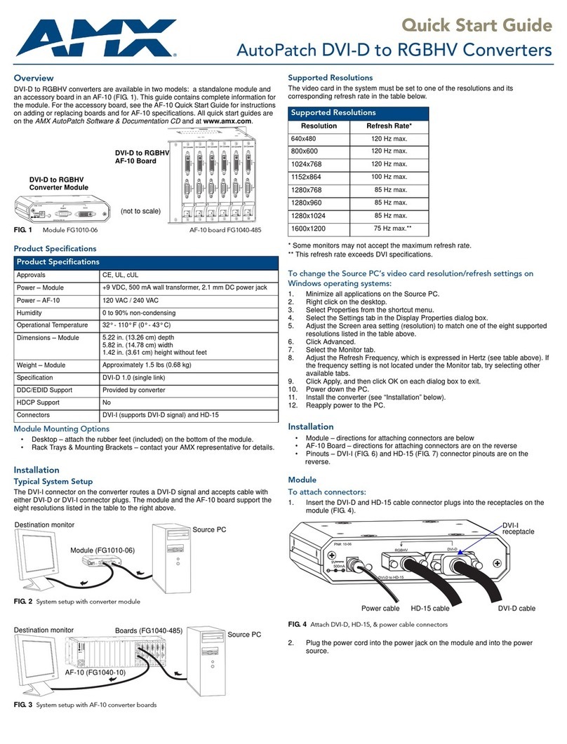
AMX FG1010-06 quick start guide

AMX

AMX FG1010-06 quick start guide

Midian PDE-1 instruction manual

Midian

Midian PDE-1 instruction manual

Audio Analogue VIVACE DAC owner's manual

Audio Analogue

Audio Analogue VIVACE DAC owner's manual

SC&T HUE03-4K user manual

SC&T

SC&T HUE03-4K user manual
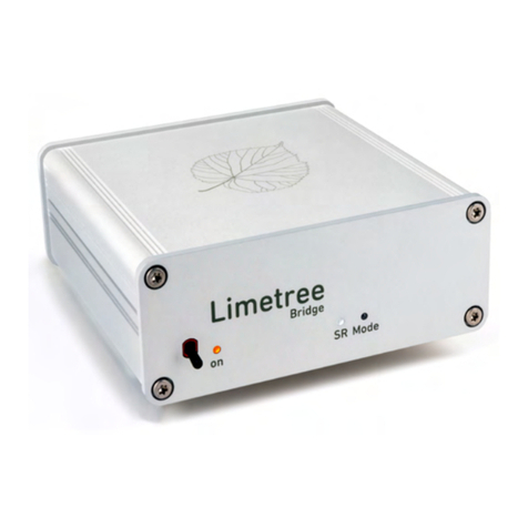
Lindemann LIMETREE BRIDGE II manual

Lindemann

Lindemann LIMETREE BRIDGE II manual
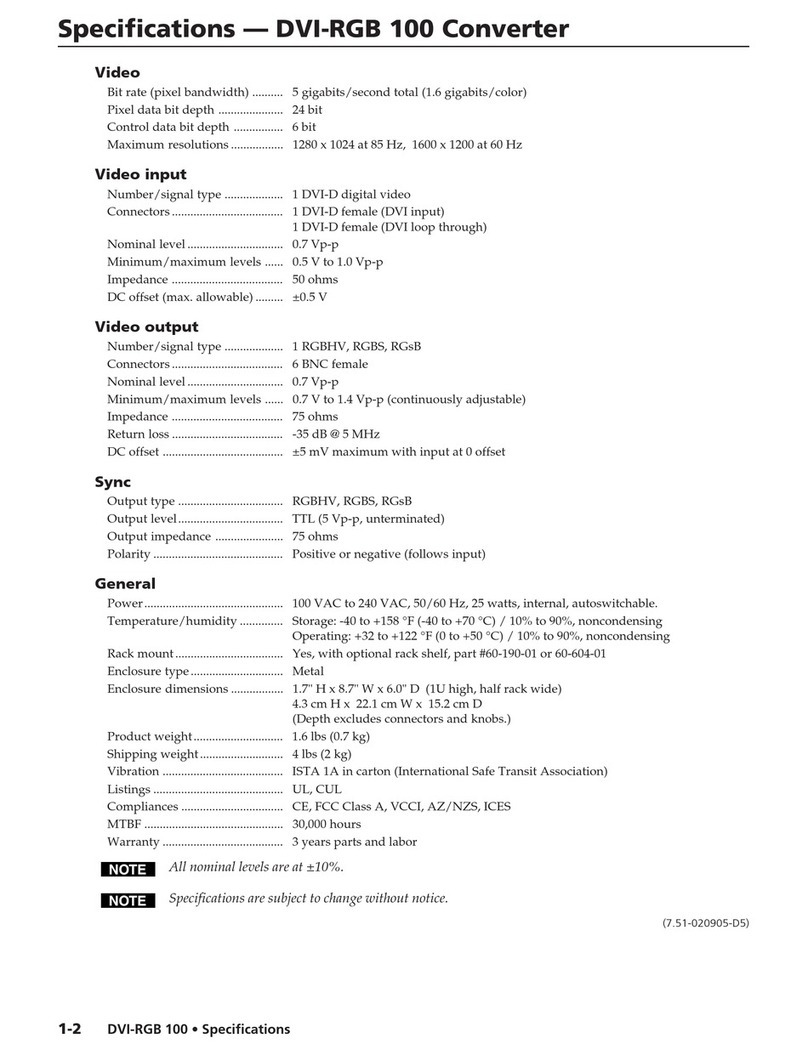
Extron electronics DVI to Analog RGB Video Converter DVI-RGB... Specifications

Extron electronics

Extron electronics DVI to Analog RGB Video Converter DVI-RGB... Specifications

Insignia NS-DXA3 user guide

Insignia

Insignia NS-DXA3 user guide

TR-Electronic CEV115M-4096/4096 V000 PROFIBUS 85ZB20N manual

TR-Electronic

TR-Electronic CEV115M-4096/4096 V000 PROFIBUS 85ZB20N manual

manuals.online logo
manuals.online logoBrands
  • About & Mission
  • Contact us
  • Privacy Policy
  • Terms and Conditions

Copyright 2025 Manuals.Online. All Rights Reserved.