Nokia OZO camera User manual

OZO CAMERAOZO CAMERA
Box ContentBox Content
11.. Protective Cover (comes fitted to camera)
22.. Large tripod adapter (comes fitted to camera)
33.. OZO Professional VR Camera PC-01

44.. Media Cable MC-01, for USB3 data transfer to computer directly from Media Module or
cartridge in Docking Station.
55.. Docking Station DS-01, for battery charging and data transfer
66.. Small tripod adapter
77.. Camera External AC power supply and AC cables
88.. Docking Station AC power supply and AC cables
99.. 3G-SDI adapter card in protective ESD bag, for external recording/monitoring
1010.. T6 tool, for removing Connector Cap of power/SDI slot
1111.. Digital Cartridge DC-01, including 33Wh Li-Ion rechargeable battery
1212.. Media Module MM-01, including 500GB solid state storage
The Protective NANUK 950 carrying case is intended for normal transportation of OZO and
included accessories. Please keep the cardboard shipping box and packing, and reuse when
transporting the camera by courier or shipping agent.
NOTE: Due to the size the case should travel as hold luggage when flying with OZO but the
cartridges (containing Li-Ion batteries) should be removed and carried as hand luggage
according to international regulations.
BASICSBASICS
Camera HandlingCamera Handling

This is the most reliable way of handling the
device.
Lift the Camera at the "tail" applying a firm
and safe grip.
Additionally you can hold the device by the
OZO Tripod adapter if it is properly attached.
MountingMounting

Securely mounting a base plate (A) to the
tripod adapter (B) is recommended.
The Device is delivered with the large OZO
Tripod adapter attached.
The large OZO tripod adapter includes 5 x
standard 3/8" tripod mounting hole.
The included alternative small OZO tripod
adapter includes 1 x standard 3/8" tripod
mounting hole.
Changing the Tripod AdapterChanging the Tripod Adapter
Specific force is required to ensure the newly-
attached tripod adapter is securely fixed.
1. Carefully remove the mounted adapter (A)
using an M8 tool.
2. Attach the alternative adapter (B).
3. Apply exactly 20 Nm with a torque wrench
tool and fix securely. Do not overtighten.
Do not replace the M8 screw.
If damaged, always replace with original spare
parts.
Connector Cap RemovalConnector Cap Removal

For streaming data through SDI and supplying
external power, remove the connector cap (A)
located below the "tail" section by using the
provided T6 Torx tool.
For stand alone use, place the connector cap
back in the slot and tighten by hand without
excessive torque.
This cap provides basic sealing and protection
for the SDI and power connectors.
Connecting SDIConnecting SDI
Attaching 3G-SDI card Carefully remove the
3G-SDI SFP+ card (A) from the ESD bag, and
insert it firmly into the SFP+ socket (B).
To remove, lift the latch (C) on the SDI card
and carefully apply backwards pressure to the
frame of card, NOT to the DIN sockets.
Attaching SDI DIN cable Attach a standard SDI
DIN connector (D) to the lower DIN socket
shown by arrow facing away from device.
To remove the cable, lift the cover of the DIN
connector, and apply pressure.
Take care not to apply lateral force to the DIN
sockets. Use cable strain relief where
necessary, otherwise damage may occur.
Connecting PowerConnecting Power

Insert the external power plug into the device
firmly, and rotate the lock ring (A) clockwise
until it is tight.
Always ensure the external plug is fully
inserted, otherwise the device may not power
up, or may use battery power only.
Cartridge ReplacementCartridge Replacement

Before you start make sure the device is
stable and mounted correctly.
1. Pull the latch (A) to it's full extension to
release the cartridge. Do not pull the cartridge
while doing so.
2. Pull the cartridge (B) out (and close the
latch).
3. To insert the cartridge pull the latch to it's
full extension.
4. Insert the cartridge with the groove
pointing downwards until you notice
resistance.
5. Release the cartridge and close the latch.
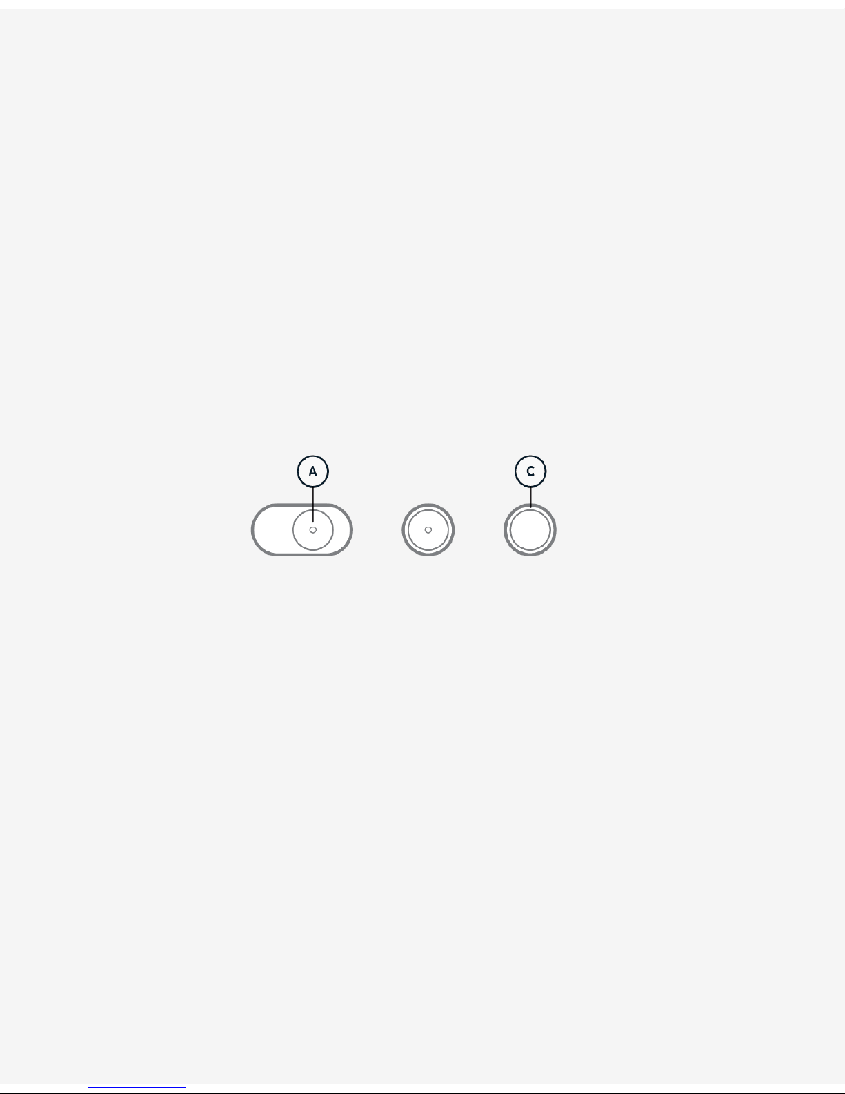
Charging BatteryCharging Battery
Insert a Digital Cartridge (A) into the Docking
Station (B).
Ensure a power cable is connected to the
Docking Station.
The LED on the Docking Station (C) should
flash white to indicate charging is in progress,
and show solid white to indicate when the
Digital Cartridge battery is fully charged.
Charging an empty battery can take up to 3
hrs.
A Digital Cartridge must be inserted at least
once to a powered Docking Station before it
can be used in the device.
A red light indicates a problem. Slow flashing
red indicates "No Battery found". Solid red
indicates "Cannot charge" (broken or
misplaced battery). Fast flashing red indicates
a malfunction.

Extracting DataExtracting Data
Connect the supplied USB cable from the
Docking Station (A) to a computer with the
OZO Creator application installed.
Insert the Digital Cartridge (B) with a Media
Module inside.
Alternatively, connect the supplied USB cable
directly between a Media Module (C) and the
computer.
OZO ApplicationsOZO Applications

To download and install the OZO Applications
please follow the instructions on
ozo.nokia.com/start.
The OZO Remote Application is needed for
example to set and monitor the exposure of
the OZO Camera.
The OZO Creator Application is used to
process and deploy the captured content to
post production tools.
The OZO Preview Application is a tool to
quickly access and view rendered content like
editorials for audio mixing.
OZO Applications require an Apple Mac Pro®
6-Core Dual GPU using OS X 10.10 Yosemite
or newer.
Basic OperationBasic Operation

Power ON-OFF
To power on the device slide the power
button (A) to the outmost right position and
release. The button will stay in an intermediate
position and the indicator (LED) in the center
of the button indicates booting (by blinking
slowly).
Once the booting has finished the indicator
discontinues blinking and remains lit. The
device always boots into "Broadcasting" mode
to allow immediate preview over SDI.
For complete shutdown slide the power
button to the outmost left position.
WiFi
By default the device is enabling WiFi
immediately after booting is complete. The
WiFi-LED (B) is blinking slowly to indicate
readiness to connect.
The OZO Remote host computer must have
WiFi enabled to connect to the OZO Camera.
The WiFi-button indicator discontinues
blinking and remains lit to indicate a
successful connection to the OZO Remote
Application.
To boot the device without WiFi (airplane
mode) press and hold the WiFi button during
startup until booting has finished.

Oculus Rift DK2 SetupOculus Rift DK2 Setup
1. Download and install Oculus Runtime for OS X version 0.4.4-beta from:
https://developer.oculus.com/downloads/pc/0.4.4-beta/Oculus_Runtime_for_OS_X/
2. After installing the Runtime connect the Oculus DK2 HDMI and USB cables to your Mac.
3. Having connected the DK2 open the Display settings from the System Preferences (click the
Apple logo in the top-left-corner of your display).
4. Select the Arrangement tab (1) and make sure the "Mirror Displays" (2) checkbox is
unchecked, and the Rift DK2 display is positioned on the right side of the main display (3). The
size of the main display may vary depending on your display resolution.
NOTE: You can have only one main display, and no additional secondary displays connected
when using OZO applications with the Oculus Rift DK2.
Broadcasting over SDI
You can switch from Standby-mode to
Broadcasting either by sliding the power-
button (A) to the outmost right position and
release (as you did for power on) or by using
the controls in the camera-mode panel of the
OZO Remote Application.
Repeat this procedure to return back to
Standby mode.
During Broadcasting a red LED ring around the
Capture-button blinks regularly "once in a
while" to indicate that the Camera is "On the
Air".
To monitor the live image from the Camera
make sure the SDI adapter and cables are
connected to your OZO Remote host
computer.
Use the Capture Settings panel in OZO Remote
to set the exposure.
Capturing
Press the Capture button to start or stop
capturing to the internal storage.
While capturing to the internal Media Module
the Capture button indicator (C) is
continuously on. Blinking slowly signals "less
than 5 minutes left".
Blinking fast signals "storage is full". These
limits are also reflected in the "Storage" status
group in OZO Remote.
NOTE: To capture on external storage set the
Camera to Broadcasting instead and use the
controls on the external device.

Note: The Rift DK2 display may be in portrait orientation and it must be rotated to landscape
orientation. This gets fixed by applying the correct settings:
5. Click the "Gather Windows" button (4) to bring the "Rift DK2" settings window to the main
display and apply these following settings (5) to (7):
Resolution: Best for display/ Rotation: 90°/ Refresh Rate: 75 Hertz

6. After changing the settings, you might need to click "Gather Windows" (8) again to access the
Rift DK2 settings. You need to confirm (9) the changes within 15 seconds to keep them.

Compatible SDI AdapterCompatible SDI Adapter
OZO can be used together with Blackmagic SDI adapters. The adapter requires driver installation
only. No additional setup is needed. Please visit https://www.blackmagicdesign.com/support for
download and support.

REMOTEREMOTE
IntroductionIntroduction
OZO Remote is an application that allows you to remotely and wirelessly control the OZO Camera
and live preview captures. It is needed, for example, to set and monitor the exposure of the OZO
Camera.
The application is composed of two main areas:
The column on the left side of the window focuses on the connection, control and monitoring of
the Camera. It is composed of different panels that you can open and close at will depending on
your needs.
The big area on the right is focused on the preview of the SDI signal provided by the Camera.
The control of the Camera happens via Wi-Fi, while the preview is done via SDI cables. The
intended setup is to connect WiFi and SDI both to the same OZO Camera.
Connecting WiFi and SDI each to different Cameras is theoretically possible but not intended.
Please observe the application as it may appear dysfunctional with that setup.
OZO Remote is also used to format the OZO Media Module in the Camera.
Controlling the OZO CameraControlling the OZO Camera
You can control the Camera with the panels located on the left side of the window. Different
elements are provided to connect, change the capture settings, capture and monitor the battery
and storage levels of the Camera.
Connecting to and Disconnecting from Camera via WiFiConnecting to and Disconnecting from Camera via WiFi
Make sure the OZO Camera is powered on and that your computer has Wi-Fi enabled. The
Camera will appear in OZO Remote in the panel of OZO devices. The panel includes both
currently available and previously connected Cameras.

Click on the Camera in the panel to connect.
To disconnect, use the command "Disconnect" from the "Connection" menu.
The wireless range will depend on the operating environment, and is consistent with other Wi-Fi
802.11 systems, that is typically 50-200 ft (15-16-m).
Broadcasting and StandbyBroadcasting and Standby
OZO Cameras can be in broadcasting or standby mode. In broadcasting mode, video is sent out
over SDI. In standby, the Camera is in low energy consumption mode and video is not sent out.
When the device is powered on, it is automatically set to broadcasting mode by default. To
switch between these modes, click on the Camera mode button.
CapturingCapturing
To start and stop capturing with the connected Camera, click on the Capture button in the
Camera Mode panel.
Captures will be stored in the internal SSD of the connected Camera.
Illuminant SettingIlluminant Setting
To set the illuminant of the connected Camera use the Illuminant control in the Capture Settings
panel.
This illuminant is set on the Camera and will be used while capturing. Alternatively, if you want to
change the illuminant only for preview purposes without affecting the Camera illuminant setting,
use the preview illuminant setting located in the monitoring area.
Exposure SettingExposure Setting
To set the exposure of the connected Camera use the Exposure control in the Capture Settings
panel.
Power StatusPower Status
To monitor the usage of the power, open the Power panel.
The Power panel indicates if the Camera is currently plugged to external power or using the
battery in the Digital Cartridge.
The panel provides the remaining battery level in any case, but observe that the battery gets re-
charged only with the OZO Docking Station.
StorageStorage

To monitor the usage of the SSD, open the Storage panel.
The panel displays information about the remaining capture time or capacity. To toggle between
these options, click on the indicator.
You will be alerted when running out of storage.
TemperatureTemperature
To monitor the temperature of the device, open the Temperature panel.
The panel displays information about the current temperature in °F or °C. To toggle between
these options, click on the indicator.
You will be alerted when reaching the overheating limits .
Audio GainAudio Gain
Audio monitoring gain can be used to change the loudness of the monitored spatial audio.
Please note that this setting does not affect the stored audio. Instead, audio is always stored
with full dynamic range.
Monitoring the SDI SignalMonitoring the SDI Signal
The tools located on the right area allow to monitor the SDI signal broadcasted by the OZO
Camera. The tools include alternative ways to view the signal, clipping indicators and preview
illuminant.
SDI SignalSDI Signal
The SDI signal is provided by the connected OZO Camera. If the SDI signal is not displayed by
OZO Remote, make sure the SDI cables are properly attached to the Camera, an SDI adapter has
been set up in your computer and the connected OZO Camera is in broadcasting mode.
Channel GridChannel Grid
The streams from the 8 lenses of the Camera are displayed in native equidistant fisheye
projection mode by default. This allows previewing all angles of the video streams.
The rectilinear mode is used when objects in the scene need to be monitored in their natural
appearance.
To switch to rectilinear mode, use the toggle buttons in the toolbar or the "Rectlinear View"
command in the "View" menu.

Double-clicking on any stream enters or exits the single Camera mode.
Combining the rectilinear and single Camera mode allows free panning through the scene.
Live Preview with Oculus Rift DK2Live Preview with Oculus Rift DK2
OZO Remote supports interactive Live Virtual Reality Preview with an Oculus Rift DK2 headset.
Follow the headset setup instructions to use it with OZO Remote.
You can toggle the preview between your computer display and the headset with the HMD
button in the toolbar or the "View in HMD" command in the "View" menu.
Toggling to HMD is disabled if the headset has not been installed in the computer, it is not
connected at that moment or there is no SDI signal to preview.
Preview IlluminantPreview Illuminant
The preview illuminant changes the illuminant for preview purposes without affecting the
Camera illuminant setting. This can be useful if multiple OZO Remote instances are being used
for monitoring the same Camera at the same time.
To enable the visual override of the Camera illuminant, toggle the preview illuminant button on.
Then select the preview illuminant from the adjacent control.
Although changing the Camera illuminant setting is faster with the Illuminant Setting control in
the Capture Settings panel, it is also possible to apply the preview illuminant to the Camera
illuminant with the "Apply to Camera" button.
To disable the visual override of the illuminant, just toggle the preview illuminant button off.
Clipping and ZebraClipping and Zebra
Clipping indicators are useful tools to set the exposure.
The preview toolbar provides 3 controls for lowlight clipping, highlight clipping and a custom
zebra midband.
Hovering on any of these controls will show the clipped areas in the lenses views. Clicking on the
controls will toggle them on so the clipped areas will be shown permanently until toggled off.
To change the range of the zebra midband use the adjacent control.
Freezing the ImageFreezing the Image
To freeze the video and get a high resolution image, use the freeze button in the toolbar or use
the "Freeze" command in the "View" menu.
To unfreeze the image and resume to live signal, use the same button.

Managing the OZO Camera SettingsManaging the OZO Camera Settings
OZO Remote can be used to upgrade the Camera firmware and calibration file.
Firmware UpgradeFirmware Upgrade
It is important to keep the firmware updated with the latest releases to ensure the device
operates with optimum stability and performance.
Assuming an internet connection is available, OZO Remote informs whenever a new firmware is
available for upgrade. Additionally, you can check the current firmware version of the Camera
and upgrade if available in the application Preferences.
Calibration File UpgradeCalibration File Upgrade
Calibration files are needed to optimize the quality of the captured media.
In order to ensure the optimum results, it is important to keep the calibration files updated to
the last version.
Use the application Preferences window to check the current calibration file number of the
Camera and upgrade.
UninstallingUninstalling
To uninstall OZO Remote from your computer, run OZO Uninstaller located in Applications > OZO
> Utilities.
CREATORCREATOR

IntroductionIntroduction
The OZO Creator Application is used to process and deploy the captured content to post
production.
OZO Creator uses a project-based approach that allows the user not only to import, preview and
export assets but also to cut and render simple compositions for the purpose of previewing
content in production.
A Stage is used to collect assets into the project. Items on the Stage are mainly previewed or
exported to other post-production tools. Processed assets can also be re-imported for further
analysis or distribution.
The timeline composition tool acts as multi-purpose cutting table. This tool can for example be
used to compare clips or to layout storylines for audio mixing.
ProjectsProjects
The purpose of projects is to organize files as collections of assets that relate to each other.
Each project has a timeline where these assets can be combined into stories.
ImportingImporting
WorkflowWorkflow
The basic OZO Creator workflow of managing assets starts by importing files that were captured
by the OZO Camera on either the OZO Media Module or an external drive to the Stage.
To import assets to the Stage you can use any of the import options in the "Stage" menu (or the
import-button below the Stage).
Processing FilesProcessing Files
Files on external drives are stored in the .mov format while files on the Media Module are stored
in a proprietory format called .ozoraw. Importing these formats to the Stage automatically
applies a basic processing that is required to later export or use the files on the Timeline.
Other manuals for OZO camera
2
Table of contents
Other Nokia Security Camera manuals