nokka 2051P User manual

2051P, 2651P, 2951P, 2962P, 3467P, 3767P
3970P, 4772P, 4872P, 4780P, 6700P
GRAPPLE LOADER
Installation, operation and
maintenance manual
NOKKA OY
Forest Line Forest Line
PL 4, 40951 Muurame FIN-40950 Muurame, Finland
Puhelin 044 7624 510 Tel. +358 44 7624 510
Telefax (014) 3100 206 Fax +358 44 3100 206
0351600

CONTENTS
Page
To the owner...........................................................................................................1
Declaration of compliance with EC directives..........................................................1
Labels and signs............................................................................................... 2 - 3
1. Before use ................................................................................................... 4 - 6
Measurement units.........................................................................................4
Directions........................................................................................................4
Serial number .................................................................................................4
Safety instructions .................................................................................... 4 - 5
Noise prevention.............................................................................................6
Minimum distances from live electric conductors............................................6
Driving on a road.............................................................................................6
Inspection during use......................................................................................6
Structural changes..........................................................................................6
2. Operating the machine................................................................................ 7 - 20
Properties of the machine in brief...................................................................7
Technical specifications............................................................................ 7 - 9
Maximum lifting table............................................................................ 10 - 15
Preparing for use .................................................................................. 16 - 17
Inspection of assembly.................................................................................18
Working instructions .....................................................................................19
Transport position.........................................................................................20
3. Maintenance.............................................................................................. 21 - 26
Safety during maintenance work...................................................................21
General maintenance instructions ................................................................21
Lubrication instructions......................................................................... 21 - 22
Adjusting the support bearing of gear rack...................................................22
Powerless loader motions.............................................................................22
Hydraulics.....................................................................................................23
Changing hydraulic hose ..............................................................................23
Adjusting the telescope chains on Nokka 4780............................................24
How to order spare parts ..............................................................................25
Serial number ...............................................................................................26
Storage.........................................................................................................26
Disposal of the machine ...............................................................................26
Warranty policy.............................................................................................27
Examples of calculating for stability determination ................................ 28- 34

TO THE OWNER OF THE NOKKA LOADER
Congratulations on choosing one of the finest machines available! If you follow the
instructions contained in this booklet, the loader will provide you with a long and trouble-
free service. Familiarize yourself with this booklet before you start working with the
loader. If there are any problems, please contact your dealer or the manufacturer.
Yours faithfully,
Nokka Oy
EC DECLARATION OF CONFORMITY
Nokka Oy
PO Box 4
40951 MUURAME, FINLAND
The compiler of this technical document:
Petteri Nokkala
Teollisuustie 4
40951 MUURAME, FINLAND
guarantees that the loaders Nokka 2051P, Nokka 2651P, Nokka 2951P, Nokka 2962P,
Nokka 3467P, Nokka 3767P, Nokka 3970P, Nokka 4772P, Nokka 4782P Nokka 4780P
and Nokka 6700P on the market is in accordance with the Machinery Directive
2006/42/EC and national regulations which have been adapted to meet the directive’s
requirements.
This guarantee applies to machines starting from serial number:
Nokka 2051 P no 100
Nokka 2651 P no 100
Nokka 2951P no 100
Nokka 2962 P no 100
Nokka 3467 P no 100
Nokka 3767 P no 100
Nokka 3970 P no 100
Nokka 4772 P no 100
Nokka 4872 P no 100
Nokka 4780 P no 100
Nokka 6700 P no 100
Muurame, Finland 15 augusti 2014
_________________________
Petteri Nokkala
Managing Director
1

LABELS AND SIGNS
These labels and signs must be found on the loader. Missing ones must be renewed
immediately. Identification plate, the load and the model labels according to the loader.
1. Identification plate
HK 2051P 3TR7888 HK 2651P 3TR7901 HK 2951P 3TR7899
HK 2962P 3TR7889 HK 3467P 3TR7890
HK 3767P 3TR7891 HK 3970P 3TR7892 HK 4772P 3TR7893
HK 4872P 3TR7894 HK 4780P 3TR7895 HK 6700P 3TR7900
2

2. Loadin label HK 2051P, HK 2651P, HK 2951P, HK 2962P, HK 3467P, HK 3767P,
HK 3970P, HK 4772P, HK 7872P, HK 4780P, HK 6700P
3TR7898
3. Warning label 3TR0640 4. Manual label 3TR1320 5. Lifring point label 3TR0510
6. Model label:
Nokka-label 3TR7729
7. Motion chart label: 3TR0740
8. Danger zone label: 3TR0890 2 pc
9. Grab label: Nokka 16 3TR7680, Nokka 20 3TR768
3

1. BEFORE USE
MEASUREMENT UNITS
This Installation and Operating Manual utilises measurement units according to the
international SI measurement system.
DIRECTIONS
In this Installation and Operating Manual, the right and left side and front and rear end
of the machine are oriented from the driver perspective.
SERIAL NUMBER
Write down the serial number of your machine in the space reserved on page 26 of this
booklet. Be prepared to give the type and serial number of your machine in all enquiries
and orders relating to the machine.
SAFETY INSTRUCTIONS
NOTE!
The safety instructions in the booklet are marked with this sign. Read these instructions
with particular care.
1. Familiarize yourself with the operation manual and carefully read the safety
instructions and all labels on the machine. If the machine is to be used by another
party, make sure that the user reads the operating and safety instructions before
handing over the machine.
2. The operator must be at least 18 years old and in good health.
3. The operator must not be under the influence of any intoxicating substances or
medications.
4. Remove all loose parts from the machine which do not belong.
5. Fit the protective guards in place and ensure that they are always in place during
operation of the machine.
6. Get acquainted with all controls and instruments.
4

7. When the loader is to be serviced, cleaned or adjusted or when accessories are to
be mounted on it, place the booms of the loader in a suitable position and secure
them so that they cannot move. Turn off the tractor and set the parking brake.
8. Do not make any structural alterations in the loader that might compromise its safety
performance. It is forbidden to weld booms.
9. Do not use the machine for purposes for which it is not intended.
10.The danger area covers an area of 20 meters and in falling head use, 50 meters.
Also use extreme caution when using accessories, taking care that there is nobody
in the danger are. Always pay special attention if children are present.
11.Never leave the loader unattended (with or without a load) with the booms extended.
12.Do not wear loose or torn clothes when operating the loader.
13.Never go under the booms or load. Operate the loader only from the cab of the
tractor.
14.Observe safety distances from live electric conductors when using the machine.
15.After the first hour of operation, check all screws and nuts for tightness. Perform this
inspection on a regular basis during operation.
16.Inspect the hydraulic system for any leakages during operation and repair any faults
immediately. In concern for the environment, do not let any oil leak out.
17.When mounting the valve block please note that pressurized hydraulic hoses should
not be placed in the cab without any form of protection.
18.Use only original spare parts.
19.The controls of the loader have to be placed into the cab, which fulfils the
requirements.
20.It is forbidden to loosen support legs from the transport package before the loader is
fitted to the lower arms of the tractor - the loader will otherwise lose its stability.
Always use support legs during loader operation. Before starting work, be sure that
the combination is stable against tipping. Calculation instructions for determination
of stability can be found in the end of this booklet.
21.Use only original accessories.
5

NOISE PREVENTION
Continuous exposure to noise may cause hearing problems and even a loss of hearing.
Noise level in the workplace depends on noise insulation and the specific way the
valves are mounted. Use suitable ear protectors or ear plugs that have a sufficient
noise-dampening capacity.
When servicing the hydraulic system, use gloves to protect your skin against oii.
MINIMUM DISTANCES FROM LIVE ELECTRIC CONDUCTORS
Nominal Minimum distance Minimum distance
voltage from an uninsulated from an insulated
kV conductor, m conductor, m
<0,5 2 0,5
0,5 - 45 3 1,5
>110 5
DRIVING ON A ROAD
• On public roads, always keep equipment required by traffic laws mounted and the
lights turned on. Also keep the tractor's safety triangle in place.
• Keep the reflectors and lamps clean.
• Remember that the weight of the loader can lead to a reduction of steering control.
INSPECTIONS DURING USE
To ensure trouble-free operation, periodic inspections must be carried out. After the first
hour of use, inspect all hoses, fittings and rams for oil leaks. Perform these inspections
at regular intervals. The loader equipped with any accessory or protective guard not
presented in this booklet, is not included in the factory´s conventional delivery.
STRUCTURAL CHANGES
Do not make any structural changes in the machine without the manufacturer's consent
to avoid reducing its working capacity or safety or shortening its operational life.
6

2. OPERATING THE MACHINE
PROPERTIES OF THE MACHINE IN BRIEF
Nokka loaders are designed for wood loading in farm forestry work. When equipped
with accessories manufactured by Nokka Oy, the loaders are suitable for loading of
ground, feed, solid dung, round bales and corresponding materials used in farming.
The loader is not designed for load lifting where co-operators are working near the
load. Use of the machine for any other purpose without the manufacturer's permission
is forbidden and entails invalidation of the guarantee.
TECHNICAL SPECIFICATIONS:
NOKKA 2051 P
Weight of the loader ready for work with log grab.............................480 kg
Net lifting torque............................................................................17.5 kNm
Gross lifting torque...........................................................................20 kNm
Swing torque ......................................................................................6 kNm
Boom turning angle...............................................................................400o
Maximum reach...................................................................................5,1 m
Maximum working pressure...........................................................18.8 MPa
Minimum hydraulic pump capacity ................................................. 40 l/min
NOKKA 2651 P
Weight of the loader ready for work with log grab.............................600 kg
Net lifting torque............................................................................17.5 kNm
Gross lifting torque...........................................................................26 kNm
Swing torque ......................................................................................6 kNm
Boom turning angle...............................................................................400o
Maximum reach...................................................................................5,1 m
Maximum working pressure...........................................................18.8 MPa
Minimum hydraulic pump capacity ................................................. 40 l/min
NOKKA 2951 P
Weight of the loader ready for work with log grab.............................650 kg
Net lifting torque............................................................................23,5 kNm
Gross lifting torque...........................................................................29 kNm
Swing torque ......................................................................................7 kNm
Boom turning angle...............................................................................400o
Maximum reach...................................................................................5,1 m
Maximum working pressure...........................................................18.2 MPa
Minimum hydraulic pump capacity ................................................. 40 l/min
7

NOKKA 2962 P
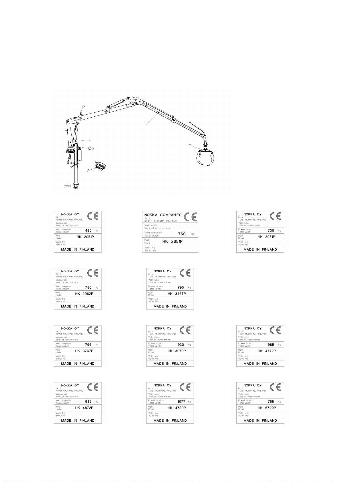
Weight of the loader ready for work with log grab.............................730 kg
Net lifting torque............................................................................23,5 kNm
Gross lifting torque...........................................................................29 kNm
Swing torque ......................................................................................7 kNm
Boom turning angle...............................................................................400o
Maximum reach...................................................................................6,2 m
Extension stroke....................................................................................1,38
Maximum working pressure...........................................................18,2 MPa
Minimum hydraulic pump capacity ................................................. 40 l/min
NOKKA 3467 P
Weight of the loader ready for work with log grab.............................795 kg
Net lifting torque............................................................................27,5 kNm
Gross lifting torque...........................................................................34 kNm
Swing torque ...................................................................................7,5 kNm
Boom turning angle...............................................................................400o
Maximum reach...................................................................................6,7 m
Extension stroke................................................................................1,38 m
Maximum working pressure..............................................................17 MPa
Minimum hydraulic pump capacity ................................................. 40 l/min
NOKKA 3767 P
Weight of the loader ready for work with log grab.............................795 kg
Net lifting torque...............................................................................30 kNm
Gross lifting torque...........................................................................37 kNm
Swing torque ...................................................................................8,7 kNm
Boom turning angle...............................................................................400o
Maximum reach with extension...........................................................6,7 m
Extension stroke................................................................................1.38 m
Maximum working pressure...........................................................18,4 MPa
Minimum hydraulic pump capacity ................................................. 50 l/min
NOKKA 3970
Weight of the loader ready for work with log grab.............................910 kg
Net lifting torque...............................................................................32 kNm
Gross lifting torque...........................................................................39 kNm
Swing torque ...................................................................................7,1 kNm
Boom turning angle...............................................................................400o
Maximum reach...................................................................................7,0 m
Extension stroke................................................................................1,38 m
Maximum working pressure..............................................................15 MPa
Minimum hydraulic pump capacity ................................................. 50 l/min
8

NOKKA 4772 P
Weight of the loader ready for work with log grab.............................965 kg
Net lifting torque............................................................................35,5 kNm
Gross lifting torque...........................................................................47 kNm
Swing torque ....................................................................................13 kNm
Boom turning angle...............................................................................400o
Maximum reach with extension...........................................................7,2 m
Extension stroke..................................................................................1.6 m
Maximum working pressure...........................................................17.2 MPa
Minimum hydraulic pump capacity ................................................. 50 l/min
NOKKA 4872 P
Weight of the loader ready for work with log grab.............................965 kg
Net lifting torque............................................................................36,4 kNm
Gross lifting torque...........................................................................48 kNm
Swing torque ....................................................................................13 kNm
Boom turning angle...............................................................................400o
Maximum reach with extension...........................................................7,2 m
Extension stroke..................................................................................1.6 m
Maximum working pressure..............................................................17 MPa
Minimum hydraulic pump capacity ................................................. 50 l/min
NOKKA 4780 P
Weight of the loader ready for work with log grab...........................1077 kg
Net lifting torque............................................................................35,5 kNm
Gross lifting torque...........................................................................47 kNm
Swing torque ....................................................................................13 kNm
Boom turning angle...............................................................................400o
Maximum reach with extension...........................................................8,0 m
Extension stroke.............................................................................2*1,25 m
Maximum working pressure...........................................................17,2 MPa
Minimum hydraulic pump capacity ................................................. 50 l/min
NOKKA 6700 P
Weight of the loader ready for work with log grab.............................765 kg
Net lifting torque............................................................................27,5 kNm
Gross lifting torque...........................................................................34 kNm
Swing torque ...................................................................................7,5 kNm
Boom turning angle...............................................................................400o
Maximum reach with extension...........................................................6,8 m
Extension stroke................................................................................1.38 m
Maximum working pressure...........................................................16,5 MPa
Minimum hydraulic pump capacity ................................................. 40 l/min
9

MAXIMUM LIFTING TABLE
Maximum lifting capacity of models Nokka 2051P, Nokka 2962P, Nokka 3467P, Nokka
3767P, Nokka 3970P, Nokka 4772P, Nokka 4780P and Nokka 6700P loaders without
the rotator and the log grab. Lifting capacities are measured according to different
boom positions. Lifting capacity is approximately 145 kg lower when operating with the
rotator and the log grab.
10

11

12

13

14

15

PREPEARING FOR USE
The loader will be supplied to retail dealer and further to the customer on a
transport stand or mounted on the loader mounting pad of the forest trailer.
Unpacking from the stand and preparing the loader for work is done in the following
way:
1. Lift the loader onto a flat base. Lift the loader a little bit up with a lifter, with which
the loader can be handled securely and cut the fastenings. Do not go under the
loader, and be careful against swinging and falling of the loader.
2. Lift the loader either on the loader mounting pad or on the four point frame
mounted on the tractor frame, and fasten the loader with bolts and nuts (M24). If
the loader is installed on the loader mounting pad having an oil tank, oil resistant
silicon will be put between the flanges to avoid leakings. Don´t allow silicon to
run into the oil tank. If the loader is fastened with the forest trailer and also the
telescopic support legs are mounted, the upper fastener of the support legs must
be mounted under the fastening bolts of the loader on the back side of the loader
at the same time. Tightening moment is 660 +/- 70 Nm.
3. Mount the valve block with the tractor so that the control levers move without any
hindrance and the valves can be easily controlled. Fasten the valve block
enough firm in order to avoid movement and falling. It is not allowed to have
unprotected pressurised hydraulic pipes in the control cabin.
4. Connect the return and pressure hoses of the loader to the tractor hydraulic
outputs. The return hose is located in the left end, seen from the hoses, and the
pressure hose is in the right end. The return hose is equipped with a female
connector, the pressure hose has a male connector. It is good to connect the
return hose directly into the tank, so there will not grow any pressure in the return
pipe line. Follow the connection instruction of the tractor manufacturer, however.
5. If support legs is mounted mount them as next ones. Fasten the hydraulic hoses
of the support legs.
6. Loosen the transport support in the transfer boom.
7. Make sure that the levers of the valve move freely in the centre positions. Turn
on the hydraulic supply.
16

8. Bend the boom jib with a movement of the transfer boom so that the boom jib is
completely bent. The grab has been fastened with the lifting boom, loosen the
grab from the boom very carefully because the grab can slip down during the
loosening (risk for accident). Lower the grab by using movements of the boom
jib. Be careful with the swinging movement of the grab when the grab is lowering
downwards, the grab or the hoses of the grab rotator can get broken or the grab
can break something when swinging.
9. Put the front gate of the trailer in its position.
10.Move all the movements of the loader some times back and forth from the end
position to the other, possible air in the system disappears. Be careful when
moving the loader because the movements can be fast if there exists air in the
system.
11.When you have moved the loader, check tightening of the tightening bolts.
Tightening of the bolts must be checked during the operation sometimes, as
well, tighten if needed.
17

INSPECTION OF ASSEMBLY
Test loading has been done in the factory and its information is registered on the log
sheet.
Equipment:
• Check that all the pins, locking pins and other parts important for safety are secured
and that the threaded joints are tight.
Operation of the control valve:
• Check that the control valve operation matches the diagram and the control levers
return to centre position (except for the extreme 'float' position).
Operation of the safety relief valve:
• By listening carefully, check that the relief valves are working.
• A pressure test can be performed from the pressure hose quick connector. Maximum
allowed pressure settings are outlined in the specifications.
Hydraulic equipment:
• Inspect the condition of the hoses and couplings and make sure that the hoses do
not rub or twist with each other.
Labels:
Check that the machine has:
• a manufacturing label
• load label/high voltage wire label
• a control valve lever operation diagram
• a danger area label
• Lifting hook label
Stability:
• Check that the loader/forestry trailer combination is stable enough against
overturning.
• Stability must be determined by either calculating using the formula in the loader
manual or experimentally, according to standard SFS 4677.
Stability determination in practice:
• A loader is considered safe if, during the test ,no more than one support point is off
the ground.
Testing requirements:
• The vehicle is tilted 5 degrees in the direction of tipping. During the test the vehicle
is in normal operating condition without load.
Test:
• The test is performed in the most unstable direction and reach using a 10%
overload. During the test all normal movements must be performed with extreme
caution.
18
This manual suits for next models
10
Table of contents