Hailo H-50 User manual

Informaon booklet
about
• Using
• Care
• Inspecon
Guided type fall arrester
including rigid anchor line -
H-50 System
Hailo SPL-50-PRO Fall Arrester and
Integrated BFD-50-136 Shock Absorber
(EU) 2016/425
DIN EN 353 -1:2018

2
Manufacturer:
HAILO-Werk
Daimlerstr. 2,
35708 Haiger, Germany
+49 (0) 2773 82-0
+49 (0) 2773 82-1561
E-mail: info @ hailo-professional.de
www.hailo-professional.de
Certifying and supervising body:
DEKRA Testing and Certification GmbH
Dinnendahlstr. 9,
44809 Bochum, Germany
Identification no. 0158
1. General information, explanation of symbols
This information booklet describes how to use,
maintain and test the SPL-50-PRO fall arrester.
For your safety, please read this information
brochure carefully before use.
If the fall arrester is resold to another country,
it is necessary for the safety of the user that
the retailer provides the user with the informa-
tion in this booklet in the respective national
language.
The SPL-50-PRO fall arrester may only be used
on the H-50 fall arrest system.
Use, maintenance and inspection must be car-
ried out exclusively in accordance with the
specifications in this booklet.
The warranty will become null and void in the
event of damage caused by non-observance of
this booklet. No liability shall be assumed for
any consequential damage arising from this.
For ease of understanding, this brochure has
replaced the term used in DIN EN 353-1:2018,
“Guided type fall arrester including rigid anchor line”,
with “fall arrest system”.
EU Declaration of Conformity and
EU-Type Test Certificate:

3
Contents:
1. General information,
explanation of symbols ......... 2
2. System data .................. 4
3. Intended use ................. 5
4. Safety instructions ............. 5
5. Technical data ................ 8
6. Use of the
SPL-50-PRO fall arrester ........ 9
7. Markings ................... 14
8. Care instruction .............. 15
9. Inspection instruction ......... 15
10. Inspection plan .............. 16
11. Documentation . . . . . . . . . . . . . . . 18
Notes on potentially dangerous situations.
If these cannot be avoided, there is a risk of injuries.
Notes on potentially dangerous situations.
If these cannot be avoided, there is a risk of severe
injuries or death.
CAUTION
WARNING
NOTE
Notes on potentially dangerous situations that may
lead to property damage.
General warning advice
Risk of fatal injury in the event
of a fall
General instructions
See documentation
Use Personal Protective Equipment
(PPE) against falls from a height
Warning of magnetic field
Warning of hand injuries

4
SPL-50-PRO fall arrester:
BFD-50-136 shock absorber
No.
No.
Expiry date:
Company:
Fax:
Postcode,
Town:
Name:
Telephone:
Street:
E-mail:
Date of the
first use:
. . . . . . . . . . . . . . . . . . . . . . . . . . . .
. . . . . . . . . . . . . . . . . . . . . . . . . . . .
. . . . . . . . . . . . . . . . . . . . . . . . . . . .
. . . . . . . . . . . . . . . . . . . . . . . . . . . .
. . . . . . . . . . . . . . . . . . . . . . . . . . . .
. . . . . . . . . . . . . . . . . . . . . . . . . . . .
. . . . . . . . . . . . . . . . . . . . . . . . . . . .
. . . . . . . . . . . . . . . . . . . . . . . . . . . .
. . . . . . . . . . . . . . . . . . . . . . . . . . . .
. . . . . . . . . . . . . . . . . . . . . . . . . . . . . . . . . . . . . . . . . . . .
. . . . . . . . . . . . . . . . . . . . . . . . . . . . . . . . . . . . . . . . . . . .
. . . . . . . . . . . . . . . . . . . . . . . . . . . . . . . . . . . . . . . . . . . .
Date Signature of manufacturer (Company stamp)
Information on SPL-50-PRO fall arrester
Date Signature of user
Information on User
2. System data

5
• Onlypersonswhohavebeeninstructedinthe
use of vertical ladder and fall protection systems
may use the H-50 fall protection system and the
SPL-50-PRO fall arrester. The user of the fall ar-
rest system must be physically and mentally ca-
pable of movement using the respective equip-
ment. Safety in normal or emergency conditions
must not be compromised.
• Thecontractororoperatorofaplantmustputin
place a plan which covers all possible emergen-
cies that might arise when using the fall arrest
system and outlines the measures required for
rescuing personnel.
• Theaccidentpreventionregulations
DGUV regulation 1 and
DGUV rules 112-198/199 (Germany)
must be respected.
Testing must adhere to the respective national
operating and testing regulations.
• Nochangesoradditionsmaybemadetothe
H-50 fall protection system without the pri-
or written consent of Hailo. Repairs may only be
carried out using original parts and in accor-
dance with Hailo‘s instructions.
• TheSPL-50-PROfallarresterisdesignedforuse
in temperatures ranging from - 40°C to + 50°C.
The safe function of the fall arrester can be im-
paired e.g. by extreme climatic conditions, che-
micals, contamination or mechanical influences
(sharp edges, oil, ice, etc.). Use in this case is
prohibited.
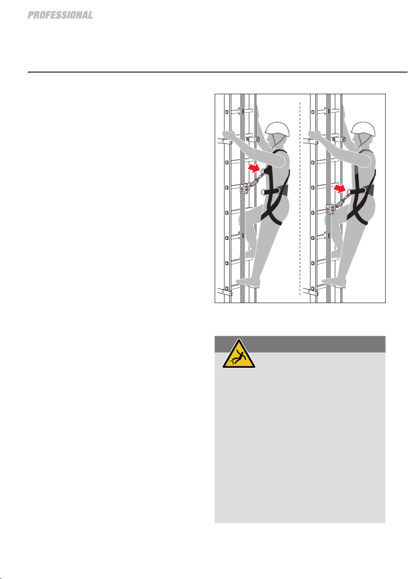
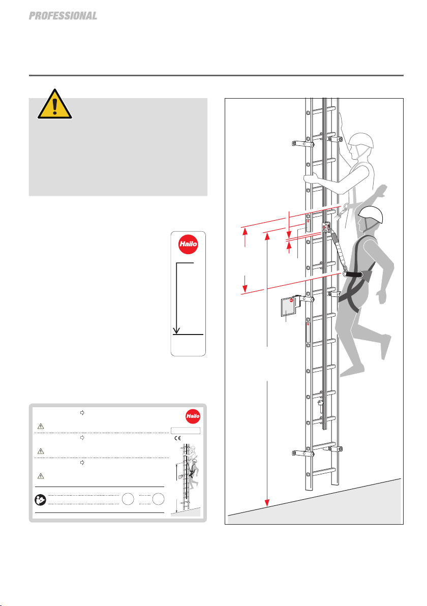
• Nomorethan5personsmayusethefallarrest
system at the same time. The distance between
individual users must be at least 6 m.
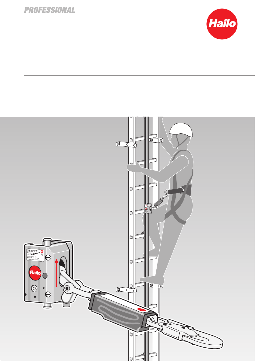
• TheH-50fallarrestsystemisdesignedasafall
safety when using rung ladders and pole clim-
bers, both above ground and below ground.
It is designed for a safe ascent and descent of
service personnel to workstations at higher or lo-
wer levels.
• TheSPL-50-PROfallarresterisapprovedexclu-
sively for securing persons with a total weight
(body weight of the user including clothing and
equipment) of 50 - 136 kg.
The use of climbing aids is prohibited unless the
safe usability of the combination in question has
been explicitly demonstrated.
• UsersoftheH-50fallarrestsystem,alongwith
their fall safety personal protective equipment
(PPEgA), connect to the fall arrester, which runs
along the entire length of the ladder system.
(see page 6).
• Thefallprotectionsystemmayonlybeused
within the operating conditions described in this
information booklet.
Any other use (e.g. as workplace positioning or
as an anchor point) is prohibited and can lead to
failure of the safety system in the event of a fall.
No liability is assumed for personal injury or pro-
perty damage resulting from violations of the
provisions outlined in this booklet or from failure
to comply with the safety instructions.
3. Intended use
4. Safety instrucons

6
4. Safety instructions
• TheSPL-50-PROfallarrestershouldonlybeper-
sonally assigned to one user.
• Whenusingacombinationofequipmentparts
(e.g. combining a user-specific safety harness
with the SPL-50-PRO fall arrester), it is a man-
datory requirement that this should not result in
any impairment of the overall system.
In the event of a fall, any impairment may result
in the failure of the fall arrester.
• Onlyapprovedsafetyharnessesaccordingto
EN 361 may be used.
• Forreasonsofsafety,theuserisnotpermittedto
grip or manipulate the fall arrester while climbing
or descending, except when the user is in a posi-
tion of safety and there is no risk of falling.
• Avisualinspectionofthefallprotectionsystem
and an inspection of the functionality of the fall
arrester must be carried out before each use,
(see page 12).
If there is any doubt about the safe use of the
device, or if the device has been damaged as
a result of a fall, it must be immediately with-
drawn from use and returned to Hailo for inspec-
tion and repair.
In the event of a fall, the ladder or the fall pro-
tection rail must also be inspected by a compe-
tent/qualified person before further use.
• Additionallanyardsarerequiredwhenleaving
the fall protection system. These should be as
short as possible in order to reasonably limit the
fall distance.
• Additionalattachingelements,e.g.Yharnesses,
should only be attached to the fastening-points
provided for them (EN 795).
[A]
WARNING
Risk of falling!
The spring hook on the shock absorber may only
be attached to the authorised retaining eye on
the safety harness [B].
The fall arrester must not be connected to any
retaining eyes to the sides of the safety harness
that may be provided as an additional element in
the hip area.
The safety harness must sit firmly on the body
and be correctly adjusted [C], [D].
A loose safety harness is prohibited when using
the fall protection system [D] [E].

7
[B]
[D]
[C]
[E]
[F]
WARNING
Risk of falling!
The user should basically avoid standing in a
position on the fall arrest rail where they are
directly above the fall arrester [F].
Warning “Risk of falling”!

8
Informationsbroschüre beachten!
Zutreffendes bei der Montage eintragen bzw. ankreuzen.
Observe Information Manual!
For assembly, enter or tick as applicable.
Lire attentivement le manuel d’information.
Pour le montage, entrez au pointez selon le cas.
Nächste
Prüfung
Next
inspection
Prochaine
inspections
06-2021 (DE-GB-FR) Hailo-Werk •Daimlerstraße 2 •35708 Haiger, Germany
Montiert
Assembled
Monté
HAILO System H-50 Das System H-50 darf ausschließlich mit dem Auffanggerät SPL-50-PRO
in Verbindung mit Auffanggurten nach EN 361 genutzt werden.
HAILO H-50 System
ATTENTION!
•
The safety harness provides protection from a height of 3 m above the access level! (Safety distance = 3 m)
• There should always be a gap of at least 6 m between any two peolpe on the fall arrest system.
• No more than 5 persons may use the fall arrest system at any one time.
The H-50 system may only be used with the SPL-50-PRO fall arrester
in conjunction with EN 361 compliant safety belts.
HAILO Système H-50
ATTENTION ! • L’effet protecteur de l’antichute n’est réalisé qu’àpartie de 3 m de hauteur au-dessus
du niveau d’accès ! (distance de sécurité = 3 m)
• Entre deux personnes utilisant l’accès une distance d’au minimum 6 m doit être respectée.
•
5 personnes au maximum peuvent utiliser en même temps le système de protection d’accès en hauteur.
Le système H-50 doit être utilisé exclusivement avec l’antichute
SPL-50-PRO et avec des harnais de sécurité selon EN 361.
DIN EN 353-1:2018
0158
ACHTUNG! •
Die Schutzwirkung des Auffanggerätes ist ab 3 m Steighöhe über Zugangsebene gegeben! (Sicherheitsabstand = 3 m)
• Zwischen 2 steigenden Personen ist ein Abstand von mindestens 6 m einzuhalten.
• Max. 5 Personen dürfen das Steigschutzsystem gleichzeitig benutzen.
Sicherheits-
abstand = 3 m
Safety
distance = 3 m
Distance de
sécurité = 3 m
Zugangsebene
Access level
System H-50 / System H-8
Sicherheitsabstand
Safety distance
3m
www.hailo.de
06-2021 (DE-GB)
[B]
The SPL-50-PRO fall arrester on the H-50 fall
arrest system does not provide protection when
the user is on the lower section of the climbing
unit
(i.e. < 3 m from the top edge – access level).
Block travel
Arrest
distance
The plant operator must install an
appropriate warning notice on the
building to inform the user beyond
all doubt of the safe distance.
The H-50 fall arrest system must be
identified with a type plate at the
point of access which indicates the
type of fall arrester to be used with
the H-50 fall arrest system. [B]
Safe distance
= 3m
[A]
[A]
5. Technical data

9
CAUTION!
CAUTION!
Overview SPL-50-PRO fall arrester
• TheSPL-50-PROfallarrester[A]isattached
to the H-50 fall arrest rail before climbing/de-
scending. The SPL-50-PRO fall arrester when
attached to the rails is fitted with a BFD-50-
136 shock absorber [B] and is connected to the
user’s safety harness.
•ThexedandintegralBFD-50-136shockabsor-
ber (DIN EN 353-1:2018) must be replaced on re-
aching its expiry date. The shock absorber may
only be replaced by the manufacturer.
• TheSPL-50-PROfallarresterisdesignedsuch
that it is not possible to thread the device incor-
rectly onto the fall arrest rail.
The fall arrester cannot be opened or closed in
the wrong pulling direction.
It is also not possible to insert the fall arrester in
the wrong direction of pull from above or below
on the fall arrest rail.
[C]
6. Use of the SPL-50-PRO fall arrester
Danger of pinching!
In case of careless handling, fingers or skin can
get squeezed between the housing parts [A].
The SPL-50-PRO fall arrester may only be
used in the correct direction of pull (red arrow
pointing upwards).
The housing of the fall arrester contains
magnets which can influence the function of
pacemakers!

10
6. Use of the SPL-50-PRO fall arrester
Attaching and removing the
SPL-50-PRO fall arrester
1. Unlocking the fall arrester
Hold the fall arrester in your left hand as shown,
press in both release buttons [A] and simultane-
ously turn the brake lever [B] upwards.
2. Opening the fall arrester
Pull the slide [C] outwards using your right hand.
3. Attaching the fall arrester
Attach the fall arrester to the profile of the fall
arrest rail, first from the left and then from the
right.
4. Locking the fall arrester
Release the slide [C] first, then release both
buttons [A].
5. Check
The fall arrester must be correctly positioned,
closed and locked on the fall arrest rail.
Follow the same procedure when removing the
SPL-50-PRO fall arrester from the fall arrest rail,
but the fall arrester is first removed from the profile
of the rail from the right.
1.
2.
3.
4.
5.

11
Note on entry and exit:
End-stop
There is an additional end-stop [A] at the entry and
exit points at the bottom and top of the ladder. This
end stop prevents the fall arrester from sliding out
of the fall arrest rail unintentionally.
WARNING
Risk of falling!
Before the end stop is brought into the transit
position, the user must secure themselves with
a lanyard to a safe anchorage point (in accor-
dance with EN 795), unless they are in a safe
location where there is no risk of falling.
At no time should there be any risk of falling!

12
6. Use of the SPL-50-PRO fall arrester
Check and function test
• Bothreleasebuttons[A]mustbeinclosed
position.
• Theshockabsorber[D]mustmovefreelyonthe
fall arrester.
• Whentheshockabsorberispulledupwards,the
SPL-50-PRO fall arrester must be released from
locking and run easily up and down the rail.
• Whentheshockabsorberisreleased,the
SPL-50-PRO fall arrester must lock on the rail
within 30 mm without slipping.
• Ifthereisanydoubtastowhetheritcanbeused
safely, the fall arrester must be taken out of ser-
vice immediately.
Checking the wearing points at the brake lever
• IntheregulartestingoftheSPL-50-PROfallar-
rester, the two wear points [E] on the surface of
the brake must be tested as follows:
• LocktheSPL-50-PROfallarresteronthefallar-
rest rail. Use the feeler gauge to check the thick-
ness [F] of the wear points on the surface of the
brake.
• Ifthemeasuredvalueis≤0.05 mm, the brake
lever must be replaced. Only Hailo is allowed to
replace the brake lever.

13
• Stoppointsandstopdevicesusedinaclimbing
system are to be positioned such that free falling
and the fall height are restricted to a minimum.
The fastening point must be within the radius of
action for the user while still secured.
• Ingeneral,theusershouldalwaysselectstop
devices/stop points that are situated above
them.
Additional anchor points
WARNING
Risk of falling!
Both on entering and leaving the fall arrest
system, the user must be secured to an
approved fastening point appropriate to local
conditions to prevent falling.
The karabiner [A] is either hooked onto an ap-
proved anchor point [B] - according to EN 795 -
or another structure!
The system may only be entered or left from a
safe standing position.
At no time should there be any risk of falling!

14
[A] Type plate on
SPL-50-PRO fall arrester
[B] Security advice
[C] Test badge
[D] ArrowmarkingTHISWAYUP
[E] Type plate on
BFD-50-136 shock absorber
[F] Shock absorber address sticker
[G] Hailo Professional Logo
[H] Packaging label
7. Markings
SPL-50-PRO Fall Arrester BFD-50-136 Shock Absorber

15
Cleaning:
• Removesoilingfromthefallarresterusingonly
water and an acid-free detergent.
• Thefallarrestershouldbeallowedtodrynatu-
rally. Drying underneath or against heat sources
is not permitted.
Storage:
•TheSPL-50-PROfallarrestermustbestoredina
dry location to which the user has access.
Temperatures <-40 ° C or > +50° C or contact
with oils, acids or other corrosive liquids is not
permitted.
•TheSPL-50-PROfallarrestercanbestoredand
transported in the supplied packaging or a suit-
able container.
• DINEN353-1:2018-compliantfallarresters
must be inspected and documented for good
working order and functionality at least once a
year by trained/authorised personnel.
• Thetestingofallcomponents,eachindividual
subsystem and system must be documented.
• Inaddition,regularchecksmustbemade
depending on the respectively applicable
environmental conditions.
This can mean that the intervals between testing
are correspondingly shortened.
• Theplantoperatorisresponsibleforensuring
that testing and maintenance intervals are
observed.
Testing must adhere to the respective national
operating and testing regulations.
NOTE
Caution, damage!
Inexpert storage or transport may result in
damage to the SPL-50-PRO fall arrester and
thus to failure in the event of a fall.
8. Care instruction
9. Inspection instruction
WARNING
Risk of falling
Regular checks of the equipment are a
mandatory requirement.
The safety of the user is dependent on
the effectiveness and the durability of the
equipment.

16
Test schedule for regular testing of the SPL-50-PRO fall arrester
Annual tests are to be documented in the tables below by
trained/authorised personnel.
In the event of a claim, this documentation must be available in full as evidence.
The manufacturer must be granted access to this at all times.
Result:
10. Inspection plan
– Copy this double page when additional information needs to be entered –
1. Hailo SPL-50-PRO fall arrester General condition, check for damage, corrosion and contamination
2. Fall arrester housing Technical condition
3. Slider right Technical condition and function
4. Rail rollers Ease of movement and technical condition
5. Anti-twist lock pin Technical condition
6. Brake lever Movement, functional surfaces and technical condition
7. Brake lever (wear points) Check thickness, min. > 0.05 mm, see page 12
8. Brake lever - recuperating spring Impact and condition
9. Screw connections Technical condition and preload force
10. Cylinder pin (brake lever) Seat, condition and any safety coating
11. Magnets Technical condition, corrosion, dirt
12. Shackle Lock pin (safety sticker)
13. Cross axes Function and movement
14. Release Function and movement
15. Anti-twist Function and movement
16. BFD-50-136 shock absorber Condition, stitching and supporting belt (blue belt)
17. BFD-50-136 shock absorber Condition of packaging in heat-shrunk sleeve
18. Karabiner dip Condition, function and safety catch
19. Original markings Are the serial number, type details, etc., easily legible?
20. SPL-50-PRO fall arrester function test Use on H-50 fall arrest system
21. Period of use of BFD-50-136 Has the period of use expired?
22. Test badge for SPL-50-PRO fall arrester Has a test badge been awarded

17
Inspection 2
Date
(Month/Year)
NO YES
OK
not
OK
N0YES
Inspection 3
Date
(Month/Year)
NO YES
OK
not
OK
N0YES
Inspection 4
Date
(Month/Year)
NO YES
OK
not
OK
N0YES
Inspection 5
Date
(Month/Year)
NO YES
OK
not
OK
N0YES
Inspection 6
Date
(Month/Year)
NO YES
OK
not
OK
N0YES
Inspection 7
Date
(Month/Year)
NO YES
OK
not
OK
N0YES
Inspection 1
Date
(Month/Year)
NO YES
OK
not
OK
N0YES
1. Hailo SPL-50-PRO fall arrester General condition, check for damage, corrosion and contamination
2. Fall arrester housing Technical condition
3. Slider right Technical condition and function
4. Rail rollers Ease of movement and technical condition
5. Anti-twist lock pin Technical condition
6. Brake lever Movement, functional surfaces and technical condition
7. Brake lever (wear points) Check thickness, min. > 0.05 mm, see page 12
8. Brake lever - recuperating spring Impact and condition
9. Screw connections Technical condition and preload force
10. Cylinder pin (brake lever) Seat, condition and any safety coating
11. Magnets Technical condition, corrosion, dirt
12. Shackle Lock pin (safety sticker)
13. Cross axes Function and movement
14. Release Function and movement
15. Anti-twist Function and movement
16. BFD-50-136 shock absorber Condition, stitching and supporting belt (blue belt)
17. BFD-50-136 shock absorber Condition of packaging in heat-shrunk sleeve
18. Karabiner dip Condition, function and safety catch
19. Original markings Are the serial number, type details, etc., easily legible?
20. SPL-50-PRO fall arrester function test Use on H-50 fall arrest system
21. Period of use of BFD-50-136 Has the period of use expired?
22. Test badge for SPL-50-PRO fall arrester Has a test badge been awarded

18
HAILO-Werk
Daimlerstraße 2, D-35708 Haiger
+49 (0) 2773 82-0
+49 (0) 2773 82-1561
info@hailo-professional.de
www.hailo-professional.de
Date Reason of work: a) Regular check, b) Repair
Test outcome of the periodic inspection
Documentation of the regular inspections / repairs to the SPL-50-PRO fall arrester
Product description Manufacter / Supplier
SPL-50-PRO fall arrester
11. Documentaon
Inspecon of the SPL-50-PRO Fall Arrester
– Copy this double page when additional information needs to be entered –
Identification mark
Serial number
Date of manufacture / Expiry date Further information
Date of purchase
Date of the first use
Documentation covering regular replacement of BFD-50-136 shock absorber
Date New production number - BFD-50-136 shock absorber Expiry date

19
Repairs carried out
Name and signature of expert Date of next
regular check
The information concerning the BFD-50-136 shock
absorber is to be entered by the manufacturer and
its replacement is to be documented in the table.
The BFD-50-136 shock absorber may only be
replaced by the manufacturer:
a) Replace shock absorber and shackle
b) Fit shackle bolts with safety stickers
Bearbeiter(in) - Name und Unterschrift
HAILO-Werk
Daimlerstraße 2, D-35708 Haiger
+49 (0) 2773 82-0
+49 (0) 2773 82-1561
info@hailo-professional.de
www.hailo-professional.de
Product description Manufacter / Supplier
BFD-50-136 shock absorber
Identification mark
Serial number
Date of manufacture / Expiry date Further information
Date of purchase
Date of the first use
Inspecon of the BFD-50-136 Shock Absorber

1215919 •Revision 2021-02 •Technical changes reserved
This manual suits for next models
2
Table of contents
Other Hailo Construction Equipment manuals
Popular Construction Equipment manuals by other brands

Dynapac
Dynapac CA 251 maintenance

MetalTech
MetalTech I-CIS04 OPERATIONAL SAFETY AND ASSEMBLY INSTRUCTIONS

Larius
Larius 3000 Operating and operating and maintenance instructions

Böcker
Böcker AHK 30/1400 operating instructions

Summit Truck Bodies
Summit Truck Bodies 6629 Safety, installation, maintenance, and operation

Grove
Grove RT540E Operator's manual