SAS/op/proc/forks/op manuals/Ex/EXTREME MANUAL v13.pub 2/24/2019 Page 4 © 2014-2019 S.A.S. of Luxemburg, LLC.
S.A.S. of Luxemburg, LLC. 133 Center Drive Hwy 54, PO Box 260, Luxemburg, WI 54217 USA
Phone: 920-845-2307 1-877-SAS-FORK Fax: 920-845-2309 Web: www.sasforks.com
INTRODUCTION LETTER (PAGE 4)
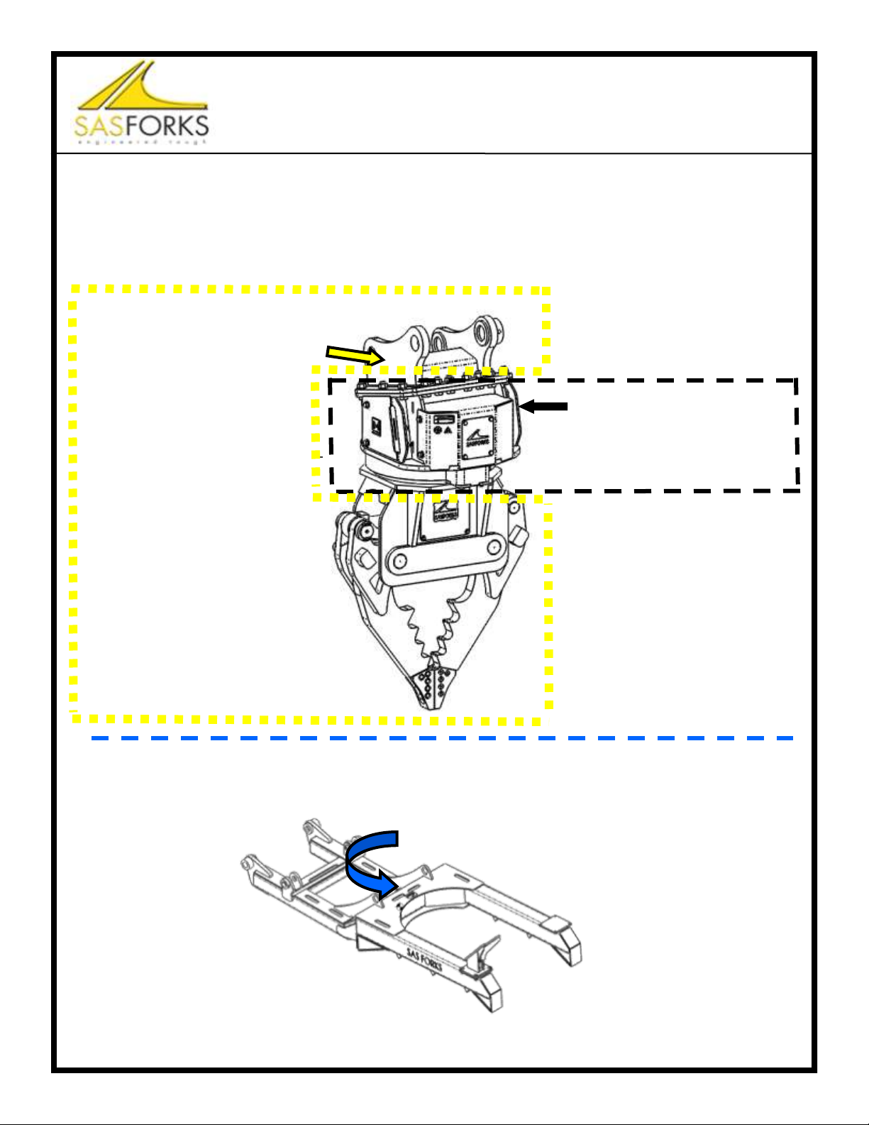
SAS™ EXTREME™ AUTO PROCESSOR
TO THE OWNERS, MANAGERS, AND OPERATORS OF EXCAVATORS
EQUIPPED WITH SAS™ EXTREME™ AUTO PROCESSOR
Safety is the most important issue in the workplace. Observing safety guidelines, equipment
capacities and using common sense will provide a work environment that is safe and efficient
for employees, management and customers. It is important that you and your operators read
and understand the information included in this manual prior to use of this equipment.
Safety warnings are highlighted through out this manual. Understanding the significance of
these symbols is important. The following is a definition of each symbol you will encounter in
this manual:
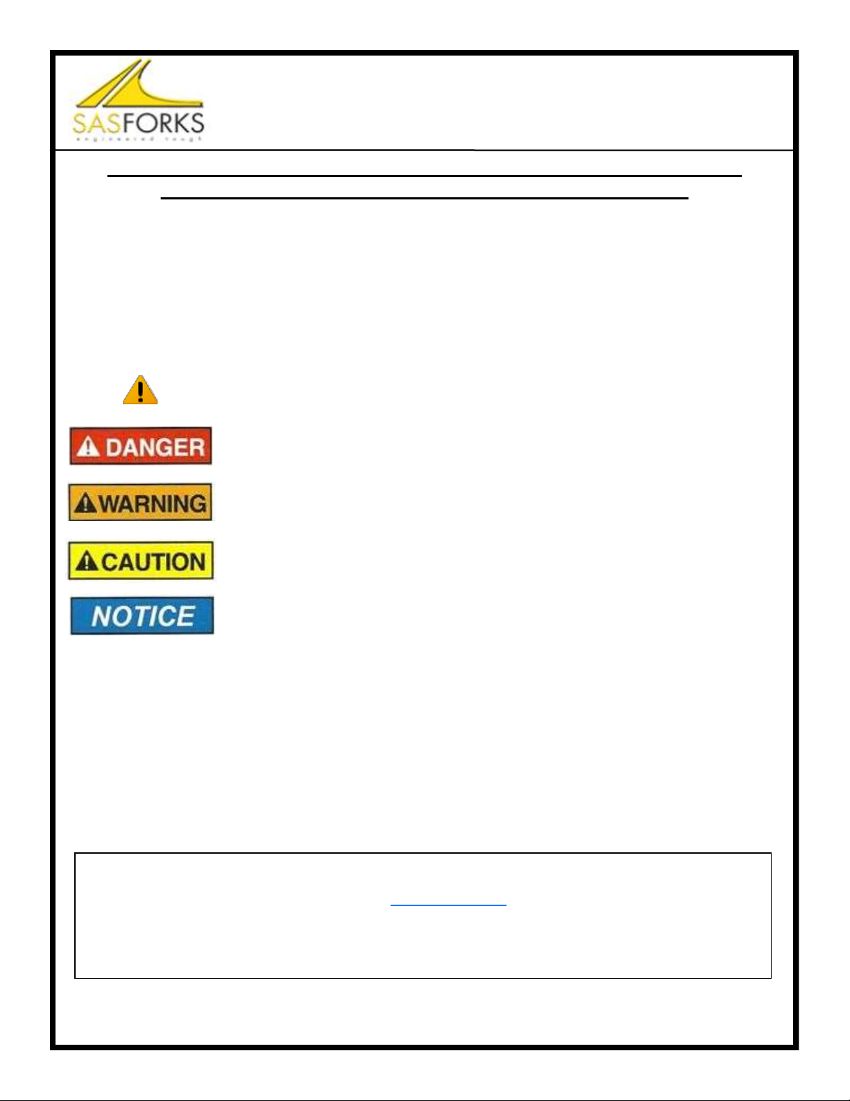
The Symbol is intended to draw your attention to important safety
information, hazard or precaution.
The Danger Symbol indicates a hazardous situation that if not avoided will
result in serious injury or death
The Warning Symbol indicates a hazardous situation that if not avoided
could result in serious injury or death
The Caution Symbol indicates a hazardous situation that if not avoided
could result in minor injury or potential property damage
The Notice Symbol indicates worst credible severity of harm is property
damage.
The following information presented in this Operator Manual for SAS FORKS™ is intended to
be a guide only, and is not meant to encompass all issues that may need to be addressed for
your particular type of business operation.
If you encounter additional information that would be helpful to us, or others, please contact us.
Thank you for your business,
SAS Ltd. Phone: Email:
133 Center Dr Hwy 54 · PO Box 260 International: 00+1+920-845-2198
LUXEMBURG, WI 54217 U.S.A.
·Proprietary Rights: All designs and other proprietary rights provided by S.A.S. of Luxemburg, LLC. to
Buyer are to remain the property of S.A.S. of Luxemburg, LLC., and Buyer shall honor all proprietary legends.
Notice: The SAS FORKS™, this operator manual, www.sasforks.com web site, the pictures, content, designs,
forks, and likeness of such, are property of S.A.S. of Luxemburg, LLC. and are protected under all applicable
Copyright, Trade Mark, Trade Dress, Patents and/or Pending Patent.
USA Patents: D672,369 ;D704,752 ; D740,861; D779,564; 9,815,128; D779,565; 9,211,832; 9,414,704; D747,170
No information, pictures, designs, products, features, or forks may be duplicated in part, entirety, or in likeness.