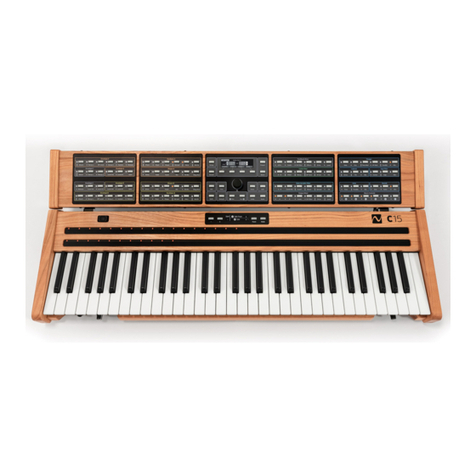
NONLINEAR LABS C15 User manual

The Synth Engine

The Synth Engine
The Synth Engine
2 3
Contents
C15 Synth Engine – Overview & Detailed . . . . . . . . . . . . . . . . . 4
Design Concepts . . . . . . . . . . . . . . . . . . . . . . . . . . . . .6
The Components in Detail . . . . . . . . . . . . . . . . . . . . . . . . 7
Oscillator A, B . . . . . . . . . . . . . . . . . . . . . . . . . . . . . 7
Shaper A,B . . . . . . . . . . . . . . . . . . . . . . . . . . . . . . . 9
Envelope A, B . . . . . . . . . . . . . . . . . . . . . . . . . . . . 13
Envelope C. . . . . . . . . . . . . . . . . . . . . . . . . . . . . . 16
Comb Filter . . . . . . . . . . . . . . . . . . . . . . . . . . . . . 17
State Variabe Filter . . . . . . . . . . . . . . . . . . . . . . . . . . 19
Output Mixer. . . . . . . . . . . . . . . . . . . . . . . . . . . . . 22
Output Mixer. . . . . . . . . . . . . . . . . . . . . . . . . . . . . 23
Flanger . . . . . . . . . . . . . . . . . . . . . . . . . . . . . . . 24
Cabinet . . . . . . . . . . . . . . . . . . . . . . . . . . . . . . . 26
Gap Filter . . . . . . . . . . . . . . . . . . . . . . . . . . . . . . 27
Echo. . . . . . . . . . . . . . . . . . . . . . . . . . . . . . . . . 29
Revrb . . . . . . . . . . . . . . . . . . . . . . . . . . . . . . . . 30
Macro Control . . . . . . . . . . . . . . . . . . . . . . . . . . . . 31
Harware Sources and Amounts . . . . . . . . . . . . . . . . . . . . 31
Voices . . . . . . . . . . . . . . . . . . . . . . . . . . . . . . . . 33
Part and Master . . . . . . . . . . . . . . . . . . . . . . . . . . . 33
Scale . . . . . . . . . . . . . . . . . . . . . . . . . . . . . . . . 34
About FM and Chaos . . . . . . . . . . . . . . . . . . . . . . . . . . 36
Synth Engine Evolution . . . . . . . . . . . . . . . . . . . . . . . . 37
The C15 Synth Engine compared to Kontour . . . . . . . . . . . . . . 38

The Synth Engine
The Synth Engine
4 5
Shaper A
PM
PM FM
PM
FB
Shaper A
Dry
EectsSVFComb
RM
RM
Comb SVFBA
Wet
Shaper B
Shaper B
L
R
L
R
FB
FB
FB
Env A
PM FB
Env Aʹ
Env Bʹ
KT
Env C
KTVel KTVelKTVel
1PM Self
1
Env A Env C Gate
Env A
Env B
Gain
Env Aʹ Env Bʹ
Env B
Gain
Env B
1
Env C
Env C KTGate
Gate
Key Pos
Env C KT
Gate
PM B
Env A
PM FB
Env C
1PM A
1
Env C KT
Env C KT
Note On
Note On
Env B
1
PM Self
Env C
Gate
Master
Level
Level
Shaper
Shaper
Shaper
Shaper
RM
Comb
RM
Reverb
So
Clip
Pan Voice Mix
FB Mix
Mix
FB Mix
Mix
A
B
A
B
A
B
A
B
Shaper
Shaper
Chirp
Filter
Chirp
Filter
Envelope A Envelope B Envelope C Gate
Shaper A
CabinetFlanger Echo Reverb
Gap
Filter
Feedback Mixer
Oscillator B
Oscillator A
Shaper B
Comb
Filter
State
Variable
Filter
Output Mixer
A
FB
Self
B
A
A
B
B
A B
FB
FB
Comb
Comb
Comb
SVF
SVF
Eects
Reverb
Wet
Dry
FB
Self
L
R
L
R
Env B Env C
Env Aʹ
Env A
Env Bʹ
Env B
Env C Gate
Env A
Env Aʹ
Gate
Env C Gate Env C
Env A
Env C
Env A Env C Env B
Env Bʹ
Gate
Env B
Env C
Shaper
FB Mix
FB Mix
Shaper
Envelope A
Oscillator A Shaper A
Comb
Filter
RM
Envelope BEnvelope C Gate
Output Mixer (Stereo)
Feedback Mixer
State
Variable
Filter
Oscillator B Shaper B
Cabinet Gap FilterFlanger Echo Reverb
C15 Synth Engine – Overview & Detailed

The Synth Engine
The Synth Engine
6 7
Design Concepts
The design goal for Phase 22 was to take advantage of digital synthesis algo-
rithms in order to build an expressively playable instrument that has a strong
individual character. At the same time the set of parameters should be small
enough to be easily accessible.
The core structure is a phase modulation synth that is based on two sine oscil-
lators and two sine shapers only. Their signals can be passed through a comb
filter, a state-variable filter, and a chain of five eects.
The Comb Filter is a tool for complex spectral shaping and also works as a reso-
nator. The State Variable Filter can be applied flexibly for subtractive filtering.
The signal routing is determined by the settings of the Output Mixer and the
Feed- back Mixer. The feedback bus can be used to create feedback loops
between dierent function blocks.
The filters and eects have an important influence on the feedback behavior:
their amplitude and phase responses determine the frequencies where the
feedback can result in self oscillation.
The Components in Detail
Oscillator A, B
The two sine wave oscillators are the only signal sources. With a random
frequency fluctuation they can also produce tunable noise. They are equipped
with three phase modulation inputs for:
• self modulation
• modulation from the other oscillator
• modulation from the feedback (FB) signal
The oscillator signal for dierent amounts of self modulation:
f
A
t
t
t
f
A
f
A
Wave Form Audio Spectrum

The Synth Engine
The Synth Engine
8 9
Oscillator signal without self modulation and dierent amounts of fluctuation:
Oscillator signal with self modulation and dierent amounts of fluctuation:
A
f
A
f
A
f
t
t
t
Audio SpectrumWave Form
A
f
A
f
A
f
t
t
t
Audio SpectrumWave Form
Shaper A,B
The signal of each oscillator is processed by a wave shaper. The shaping curve
is a sine function with adjustable foldback and asymmetry. The mix amounts
of the shaper signal can be adjusted individually for each phase modulation
branch and for the output.
The Shaper block also contains mixing points for the feedback signal and the
result of a ring modulation between the output signals of the branches A and B.
The diagrams on the following pages show the output signal depending on
Drive, Fold and Asymmetry.

The Synth Engine
The Synth Engine
10 11
The influence of the Fold parameter of the Shaper:
Drive: 12 .0 dB
Fold: 100 %
Asymetry: 0 %
Drive: 12 .0 dB
Fold: 66 %
Asymetry: 0 %
Drive: 12 .0 dB
Fold: 33 %
Asymetry: 0 %
Drive: 12 .0 dB
Fold: 0 %
Asymetry: 0 %
y
t
t
x
Input
Output
y
t
t
x
Input
Output
y
t
t
x
Input
Output
y
t
t
x
y
x
Input
Output
The influence of the Drive parameter of the Shaper:
Drive: 16 .8 dB
Fold: 100 %
Asymetry: 0 %
Drive: 12 .3 dB
Fold: 100 %
Asymetry: 0 %
Drive: 9 .0 dB
Fold: 100 %
Asymetry: 0 %
Drive: 6 .0 dB
Fold: 100 %
Asymetry: 0 %
Drive: 3 .0 dB
Fold: 100 %
Asymetry: 0 %
Drive: 0 .0 dB
Fold: 100 %
Asymetry: 0 %
y
t
t
x
Input
Output
y
t
t
x
Input
Output
y
t
t
x
Input
Output
y
t
t
x
Input
Output
y
t
t
x
Input
Output
y
t
t
x
Input
Output

The Synth Engine
The Synth Engine
12 13
Envelope A, B
These two ADBDSR envelopes are the control sources for:
• the output amplitude of the Oscillator-Shaper branch
• the Oscillators’ phase modulation depths
• the Drive (input gain) of the referring Shaper
This diagram shows the segments of the envelope:
0.0
Attack
Level
Peak Level
Breakpoint
Level
Sustain Level
t
Note On Note O
Decay 1 Decay 2 Release
The influence of the Asymetry parameter of the Shaper:
Drive: 3.4 dB
Fold: 50 %
Asymetry: 0 %
Drive: 3.4 dB
Fold: 50 %
Asymetry: 20 %
Drive: 3.4 dB
Fold: 50 %
Asymetry: 60 %
Drive: 3.4 dB
Fold: 50 %
Asymetry: 100 %
y
t
t
x
Input
Output
y
t
t
x
Input
Output
y
t
t
x
Input
Output
y
t
t
x
Input
Output

The Synth Engine
The Synth Engine
14 15
Envelope with Decay 1 as Hold Time:
Percussive Envelope:
Organ-style Envelope:
Peak/
Breakpoint
Level
0.0
Decay 2
Attack Decay 1 Release
Level
t
Peak Level
Breakpoint
Level
0.0
Decay 2
Decay 1 Release
Level
t
Peak/
Breakpoint/
Sustain Level
0.0
Decay 2
Attack Decay 1 Release
Level
t
Envelope Amount:
Envelope with multiplying eect:
Envelope with additive eect:
PM Self
Env A
Crossfade
Modulated Signal
Control Position
Multiplier
1.0
Env A
t
Decay 2Attack Decay 1 Release
Parameter
Factor
Amount
0.0
100%
75%
50%
25%
0%
Amount
PM Self
Env A
75 %
50 %
130 st
t
– 20 st
Parameter
Value
Amount
Decay 2Attack Decay 1 Release
Pitch
Env C
–80.0 st
60.00 st

The Synth Engine
The Synth Engine
16 17
Envelope C
The third ADBDSR envelope has bipolar Breakpoint and Sustain levels. It can
modulate:
• the pitches and fluctuations of Oscillator A and B
• the feedback signal
• parameters of the Comb Filter and the State Variable Filter
Envelope C shapes with dierent polarities of the Breakpoint and Sustain levels:
Envelope C - “Retrigger Hardness” Parameter (in monophonic mode):
Peak Level
Breakpoint Level
(>0)
Sustain Level
(<0)
t
t
Note On Note O
0.0
Peak Level
Breakpoint Level
(<0)
Sustain Level
(>0)
Attack Decay 1 Decay 2 Release
0.0
0.0
Level
t
Note On Note On (Retrigger) Note ONote O
0%
100%
Comb Filter
The Comb Filter contains:
• a precisely tunable delay (Pitch)
• a control for the Decay time of the impulse response
• a second-order Allpass (AP) filter
• a lowpass (Hi Cut) in the feedback loop
• a delay modulation by the Oscillator signals, similar to phase modulation (PM)
Block diagram of the Comb Filter:
AP Reson
PM
Decay
Pitch AP Tune Hi Cut
Key Position
Env C
Key Trk
Env C
Key Trk
Gate
Key Trk
Env C
Key Trk
Env C
Note On/O
Delay Time
Control
Feedback Control
Center Frequency
Control
Cuto
Control
Delay 2-Pole Allpass 1-Pole Lowpass OutIn
from A-B

The Synth Engine
The Synth Engine
18 19
Basic frequency responses of the Comb Filter. Setting the Decay to negative values
has similar results like the inverted mix.
Non-inverted Mix:
Inverted Mix:
Magnitude
(dB)
Frequency
Ratio
0 dB
– 20 dB
1.0 2.0 3.0 4.0 5.0
– 40 dB
– 60 dB
– 80 dB
Magnitude
(dB)
Frequency
Ratio
0 dB
– 20 dB
0.5 1.5 2.5 3.5 4.5
– 40 dB
– 60 dB
– 80 dB
State Variabe Filter
The State Variable Filter has a variable 4-pole structure with:
• two internal 2-pole filters with splittable cuto frequencies (Spread)
• crossfade between serial and parallel modes (Parallel)
• crossfade between lowpass, bandpass, and highpass mode (L-B-H)
• cuto frequency modulation (FM) by the Oscillator signals
Here you see a block diagram of the State Variable Filter:
L–B–H
Reson
Reson
Parallel
Parallel
FM
from A-B
FM
FM
Cuto
Spread
Key Trk
Env C
Key Position
Env C
L-B-H 1
L-B-H 2
H
B
L
H
B
L
Cut 1
Cut 2
Cut 1 Cut 2
L-B-H 1 L-B-H 2
Cuto Control
L-B-H Control
2-Pole SVF
2-Pole SVF
X-Fade
X-Fade Out
In

The Synth Engine
The Synth Engine
20 21
Frequency responses of the State Variable Filter with Parallel set to 100 %:
12 dB/oct
24 dB/oct 24 dB/oct
12 dB/oct
24 dB/oct
12 dB/oct
24 dB/oct
12 dB/oct
Frequency
0 dB
Gain
0 dB
Gain
Frequency
0 dB
Gain
Frequency
0 dB
Gain
Frequency
0 dB
Gain
Frequency
0 dB
Gain
Frequency
0 dB
Gain
Frequency
0 dB
Gain
Frequency
L-B-H = 0 %, Reson = 0…100 %
L-B-H = 100 %, Reson = 0…100 %
L-B-H = 0 %, Reson = 0…100 %
L-B-H = 0 %, Reson = 0 %, Cuto = var. L-B-H = 0 %, Reson = 0 %, Cuto = var.
L-B-H = 100 %, Reson = 0…100 %
L-B-H = 50 %, Reson = 0…100 %L-B-H = 50 %, Reson = 0…100 %
Parallel = 0 %, Spread > 0 st Parallel = 0 %, Spread = 0 st
Frequency responses of the State Variable Filter with Parallel set to 0 %:
12 dB/oct
24 dB/oct 24 dB/oct
12 dB/oct
24 dB/oct
12 dB/oct
24 dB/oct
12 dB/oct
Frequency
0 dB
Gain
0 dB
Gain
Frequency
0 dB
Gain
Frequency
0 dB
Gain
Frequency
0 dB
Gain
Frequency
0 dB
Gain
Frequency
0 dB
Gain
Frequency
0 dB
Gain
Frequency
L-B-H = 0 %, Reson = 0…100 %
L-B-H = 100 %, Reson = 0…100 %
L-B-H = 0 %, Reson = 0…100 %
L-B-H = 0 %, Reson = 0 %, Cuto = var. L-B-H = 0 %, Reson = 0 %, Cuto = var.
L-B-H = 100 %, Reson = 0…100 %
L-B-H = 50 %, Reson = 0…100 %L-B-H = 50 %, Reson = 0…100 %
Parallel = 0 %, Spread > 0 st Parallel = 0 %, Spread = 0 st

The Synth Engine
The Synth Engine
22 23
Output Mixer
The Output Mixer creates a stereo sum of the signals from Oscillator/Shaper A
and B, the Comb Filter and the State Variable Filter. It includes a sine shaper for
the sum signal of each voice.
Signal flow of the Output Mixer:
Drive Fold Asym
Level
AB Comb SVF
To FX ()
L
R
()
()
Shaper
Level
Key Pos
Pan Pan Pan Pan
Pan
Voice
Mix
Output Mixer
This mixer combines the following signals for the feedback bus: the outputs of
the Comb Filter and the State Variable Filter and the output of the Eects chain,
with a separately adjustable amount of Reverb. It includes a sine shaper for the
sum signal.
The feedback bus signal (FB) can be used for the phase modulation of the
Oscillators and it can be injected into the signal path behind the Shapers for
direct audio feedback.
In Layer Sounds the Feedback Mixer can route signals between the layered
voices. It provides an additional input for the Oscillator signals (A/B) of the
other Part, and the Comb, SV Filter and Eects channels can also receive signals
of the other Part.
Signal flow of the Feedback Mixer. The elements with “II (I)” are only available in
Layer mode:
Drive Fold Asym
Level
Shaper
KT
From ()
From ()
From ()
Dry Dry Wet Wet
From ()
Reverb Mix
A – B
A B
A/B () Comb SV Filter Eects
Dry Wet

The Synth Engine
The Synth Engine
24 25
Flanger
An LFO-modulated stereo delay plus a 4-pole allpass filter
creating a wide range of chorus, flanger and phaser eects.
The LFO can also modulate the amplitudes of the output
signals for a tremolo eect.
Signal flow of the Flanger:
Time Mod AP Mod
Time Mod AP Mod
Env Rate
Mix
Tremolo
Hi Cut
Feedback
Time
Wet
Dry
FB X
Time L Time R
Mod L
Time L
Mod L
AP Tune
Mod R
Time R
Mod R
AP Tune
FB Self FB X
FB Self
FB Self
Mod L Mod R
L
Stereo
Cross FB
Phase
LFOEnv
Feedback Control
Tremolo Amount
X-Fade
Time Control
4-Pole
Allpass
Delay
X-Fade Out L
Out R
In L
In R
50 Hz
Highpass
1-Pole
Lowpass
4-Pole
Allpass
Delay 50 Hz
Highpass
1-Pole
Lowpass

The Synth Engine
The Synth Engine
26 27
Cabinet
A stereo distortion unit (sine shaper) with pre and post filtering that can sound
similar to a guitar amp driving a speaker.
Signal flow of the Cabinet:
Drive Lo Cut Hi Cut Cab Lvl Mix
Tilt
Fold
Asym
Drive Lo Cut Hi Cut Cab Lvl Mix
Tilt
Fold
Asym
Pre Post
Pre Post
Tilt Control
Tilt Control
2-Pole
Highpass Shaper
Shelving
Filter X-Fade
Out L
In L Shelving
Filter
4-Pole
Lowpass
2-Pole
Highpass Shaper
Shelving
Filter X-Fade
Out R
In R Shelving
Filter
4-Pole
Lowpass
Gap Filter
A 4-pole lowpass and a 4-pole highpass in a parallel or serial structure, creating
a flexible band-rejection or band-pass filter. The oset between the center
frequencies of the le and the right channel can be controlled.
Signal flow of the Gap Filter:
Gap
Center
Reson
Reson
Balance Mix
Balance Mix
Reson
Reson
Balance Mix
Balance Mix
Lo Cut L
Lo Cut R
Hi Cut L
Hi Cut R Lo Cut L
Hi Cut L
Lo Cut R
Hi Cut R
Stereo
Cuto
Control
X-Fade 4-Pole
Lowpass X-Fade
4-Pole
Highpass
Out L
In L
X-Fade 4-Pole
Lowpass X-Fade
4-Pole
Highpass
Out R
In R

The Synth Engine
The Synth Engine
28 29
Some typical frequency responses:
1.00
–1 1
1.41
Balance
1.00
–1 1 Balance
0 dB
Gain
Frequency
0 dB
Gain
Frequency
0 dB
Gain
Frequency
0 dB
Gain
Frequency
0 dB
Gain
Frequency
0 dB
Gain
Gain Gain
Frequency
0 dB
Gain
Frequency
0 dB
Gain
Frequency
Balance = 0, Mix = 1, Reson = var. Balance = 0, Mix = –1, Reson = var.
Balance = 0, Reson = 0.5, Mix = –1 ... 0
Mix = –1, Balance = 0 ... –1
Mix = –1, Balance = 0 ... 1
Balance = 0, Reson = 0.5, Mix = 0 ... 1
Mix = 1, Balance = 0 ... –1
Mix = 1, Balance = 0 ... 1
Parallel/Band Reject (Mix > 0) Serial/Band Pass (Mix < 0)
A_lo A_hi A_lo A_hi
Echo
A stereo delay eect with adjustable cross-feedback.
Signal flow of the Echo.
Hi Cut
Hi Cut
Mix
Send
Send
Time Feedback
Wet
Dry
Time L
Time L
Time L Time R FB Self FB X
FB Self
FB Self
FB X
Stereo Cross FB
Time Control Feedback Control
1-Pole
Lowpass
Delay
X-Fade Out L
Out R
In L
In R
50 Hz
Highpass
1-Pole
Lowpass
Delay 50 Hz
Highpass

The Synth Engine
The Synth Engine
30 31
Revrb
A flexible simulation of rooms and halls. The Size can be varied without
artefacts.
Signal flow of the Reverb.
ChorusColorPre DelaySize
Mix
Wet
Wet
Dry
Dry
Send
Reverberation
Unit
X-Fade Out L
To FB Mixer
Out R
In L
In R
Macro Control
Six Macro Controls (A, B, C, D, E, F) are available as modulation sources. 106
parameters can be assigned as modulation targets with individual amounts.
For each Macro Control a Smoothing time can be set.
Harware Sources and Amounts
Eight physical control elements are available, that can be mapped to the six
Macro Controls:
• four Pedals
• two Ribbons
• the Bender
• Aertouch
The illustration on the next page shows how the modulation works.

The Synth Engine
The Synth Engine
32 33
The modulation stages (with example mapping):
Hardware Source Macro Control
Mod Amount
Parameter
Pedal 1
Pedal 2
Pedal 3
Pedal 4
Ⓐ
Ⓑ
Ⓒ
Ⓓ
Ⓕ
Ⓔ
Bender
Aertouch
Ribbon 1
Ribbon 2
External Devices Hardware Sources Macro Controls Target Parameters
Voices
The parameters in this group control the monophonic mode and the use of the
voices for Unison.
Part and Master
Master Volume and Master Tune are always available, while the Part groups are
used to control aspects of the two Parts of a Split Sound or a Layer Sound.

The Synth Engine
The Synth Engine
34 35
Scale
The Scale group oers twelve Osets to tune the keys of an octave. The Base
parameter can be used to shi the base key of the scale.
Equal-temperament scale and the available tuning range:
C2 C3D2 D3
+1+11+10 +2 +3 +4 +5 +6 +7 +8 +9 +10
Base
Key +11 +1 +2 +3 +4 +5 +6 +7 +8 +9
Base
Key
max.
– 800 ct
max.
+ 800 ct
Pitch
A scale where four keys have been micro-tuned:
C2 C3D2 D3
+1+11+10 +2 +5 +6 +7 +8
Base
Key +11 +1 +2 +5 +6 +7 +8
Base
Key
+3 +4 +9 +3 +4 +9+10
Pitch
–10ct
+32ct
–10ct
+32ct
+25ct
+43ct
+43ct
+25ct

Phase 22
Phase 22
36 37
About FM and Chaos
I have always been fascinated by FM synthesis (FM means frequency modula-
tion but in reality, the technique used is phase modulation). John Chowning
was the pioneer researcher in this field and Yamaha created the first commer-
cially available instruments.
For a number of years - between the end of the 80’s and beginning of the 90’s
- the Yamaha DX7-II was my main instrument. I also used several other DX/TX/
TZ/SY/TG models. These instruments were based on simple building blocks but
oered a vast potential for sound programming. The results were not easy to
predict but worth the eort. One of their most important advantages was that
they could be programmed to respond very expressively to key velocity.
The algorithms of the first FM synths already contained a feedback loop. Later,
in NI’s FM7 the algorithms were extended to a matrix where every operator’s
output signal can be sent to any operator’s input, allowing even multiple
feedback loops. In addition, all these signals can be mixed to the output. We
also learned that a filter and a distortion operator make a lot of sense in such
structures.
In an earlier stage of the Phase 22 project it was a 4-operator FM synth, but for
more simplicity and focus the frequencies of two of the sine oscillators were set
to 0 Hz, which means they became sine shapers.
An interesting lesson from “chaos theory” is that even a simple system can
behave in a surprisingly complex or “chaotic” way. A good example is a filter
with a propagation delay and a non-linear component combined in a feedback
loop with enough gain. The non-linear stage could be a wave shaper, or an
oscillator with an input for frequency, phase or pulse width modulation or for
hard sync.
The design of Spark was inspired by the early Reaktor Ensemble Weedwacker
which had a feedback from the output of the filter to the PWM input of the
oscillator. Weedwacker fascinated many users because its simple structure was
able to produce organic and chaotic sounds.
Synth Engine Evolution
Parts of the design of Phase 22 evolved from Spark and Cha-Osc and also ben-
efit from the experiences designing Prism and Skanner, which are all Reaktor
instruments developed at NI. As with Spark and Cha-Osc, the synthesizer uses
very basic waveforms — in this case only two sine wave oscillators. But the
concept behind Phase 22 is at the same time more radical and more consistent
compared to its predecessors. The result is a very symmetrical structure with a
core which is reminiscent of a two-operator FM synthesizer.
An earlier version of Phase 22 was the basis for the development of Native
Instruments’ Kontour in 2014. With the learnings from the Kontour project
we have improved Phase 22 in many aspects, and as part of the C15 it is still
evolving..
Spark (2008) Cha-Osc (2009)
Phase 22 (2013) Kontour (2014)

Phase 22
Phase 22
38 39
The C15 Synth Engine compared to Kontour
• Higher resolution for velocity, hardware controls and parameters.
• Six instead of four Macro Controls.
• Each of the Macro Controls can address around 90 parameters.
• Flexible mapping of eight physical modulation sources (bender, aertouch, 4
pedals, 2 ribbons) to the six Macro Controls.
• The Oscillators got the Fluctuation feature providing a large variety of noise
and random signals.
• Control over the Phase osets of the Oscillators.
• Phase Reset option for the Oscillators.
• The new Chirp filter allows to control the bandwidth of the phase modulation.
• The Feedback Mixer got its own shaper for improved control of the feedback
behaviour.
• Key tracking adjustable for the level of the feedback bus.
• The Feedback paths can be controlled by Envelope C.
• The Envelopes got adjustable Attack Curves.
• The Decay 1 segment of the Envelopes can work like a static “hold” segment.
• The Decay times of the Envelopes can be controlled by velocity.
• The Elevate parameter allows to set dierent Breakpoint and Sustain levels
for amplitude and timbre.
• Envelope C is now ADBDSR with bipolar levels and more destinations.
• The delay of the Comb Filter can be modulated by the Oscillators (similar to
phase modulation).
• The State Variable Filter has been re-designed to be more eective and flexi-
ble in band-pass and band-reject modes.
• Stereo Pan for the Oscillators and Filters in the Output Mixer.
• Adjustable key tracking for the Stereo Pan of voices.
• Adjustable Stereo spreading of Unison voices.
• The Flanger is now in front of the Cabinet.
• The Flanger extended by a 4-pole Allpass for phaser-like response.
• The Flanger can be controlled by a key-triggered envelope.
• The Flanger’s stereo LFO is available for Tremolo.
• The Cabinet is now a stereo eect.
• The Cabinet got more distortion and filter parameters.
• The Gap Filter now can also work as an 8-pole bandpass filter and oers
adjustable resonances.
• More control over the stereo processing of Flanger and Echo.
• The Reverb is now based on a new algorithm with a high quality and smooth
transitions between dierent Sizes.
• Split and Layer modes with two complete eect sections.
• Signal routing (cross feedback) between pairs of voices in Layer mode.
• Monophonic modes.
Other manuals for C15
14
Table of contents
Other NONLINEAR LABS Musical Instrument manuals
