Norac Topcon X25 User manual

TopconX25,X30,X35
InstallationManual

Copyright2018byNORACSystemsInternationalInc.
ReorderP/N:74UT‐TC‐X30‐INSTRevA(TopconX25,X30,X35DisplayInstallationManual)
NOTICE:NORACSystemsInternationalInc.reservestherighttoimproveproductsandtheirspecificationswithoutnoticeandwithouttherequirementtoupdate
productssoldpreviously.Everyefforthasbeenmadetoensuretheaccuracyoftheinformationcontainedinthismanual.Thetechnicalinformationinthismanual
wasreviewedatthetimeofapprovalforpublication.

WWW.NORAC.CA
PRECISIONDEFINED
Contents
1
Introduction..........................................................................................................................1
2
TechnicalSpecifications........................................................................................................3
3
Installation.............................................................................................................................4
4
CableSchematics.................................................................................................................11

WWW.NORAC.CA
PRECISIONDEFINED
Page1
Visitwww.solutions.norac.caformoresystem
installationandtroubleshootinginfo.
1Introduction
TheTopconX30DisplayOptionManualisintendedtobeusedinconjunctionwiththeUC7™BoomHeight
ControlInstallationManual.ThismanualprovidesinstructionstointerfacetheUC7HCM1Moduletothe
TopconX25,X30,andX35displays.ForinstallationoftheUC7BoomHeightControlSystempleaserefertothe
sprayerspecificmanualprovidedwiththekit.
Pleasetakethetimetoreadthismanualcompletelybeforeattemptingtoinstallthesystem.Athorough
understandingofthismanualwillensurethatyoureceivethemaximumbenefitfromthesystem.
Yourinputcanhelpmakeusbetter!Ifyoufindissuesorhavesuggestionsregardingthepartslistorthe
installationprocedure,pleasedon’thesitatetocontactus.
Everyefforthasbeenmadetoensuretheaccuracyoftheinformationcontainedinthismanual.Allparts
suppliedareselectedtospeciallyfitthesprayertofacilitateacompleteinstallation.However,NORACcannot
guaranteeallpartsfitasintendedduetothevariationsofthesprayerbythemanufacturer.
Pleasereadthismanualinitsentiretybeforeattemptinginstallation.
TheuseofdielectricgreaseisnotrecommendedonanyNORACelectricalconnections.

WWW.NORAC.CA
PRECISIONDEFINED
Page2
Visitwww.solutions.norac.caformoresystem
installationandtroubleshootinginfo.
1.1. ListofParts(Self‐PropelledInstallation)
ItemPartNumberNameQuantity
C2550250SWITCHBOX1
C2650140‐11CABLESWITCHBOXTEE‐502501
C401015764‐01CABLETOPCONX25,X30CABINTERFACE1
C411015765‐01CABLETOPCONCM‐40INTERFACE1
C4243220‐0.5CABLENETWORK14AWG0.5M3
C4343220‐10CABLENETWORK14AWG10M1
E0850200CANBUSREPEATER1
E1043760NETWORKCOUPLER3‐WAY1
E2043764TNETWORKCOUPLER2‐WAYWITHTERMINATOR 2
M01UC7‐BC‐MAN‐TECH‐IMPMANUALUC7TECHNICAL–IMPERIALUNITS1
M0474UT‐TC‐X30‐INSTMANUALUC7UTTOPCONX25,X30,X35DISPLAYKIT1
1.2. AdditionalPartsforPullTypeInstallation
Ifinstallingonapulltypemachine,thefollowingpartsareneededandmustbeorderedseparatelyfromthiskit.
ItemPartNumberNameQuantity
C4443220‐03CABLENETWORK14AWG3M1
C4543210‐15CABLENETWORK18AWG15M1
E1243764NETWORKCOUPLER2‐WAY1

WWW.NORAC.CA
PRECISIONDEFINED
Page3
Visitwww.solutions.norac.caformoresystem
installationandtroubleshootinginfo.
2TechnicalSpecifications
Table1:SystemSpecifications
SupplyVoltage(rated) 12VDC
SupplyCurrent(rated) 10A
HydraulicPressure(maximum) 3300psi
BaudRate 250kbps
OperatingTemperatureRange 0°Cto80°C
WWW.NORAC.CA
PRECISIONDEFINED
Page4
Visitwww.solutions.norac.caformoresystem
installationandtroubleshootinginfo.
3Installation
ThefollowingstepsoftheinstallationassumethattheHCM1moduleandallrequiredcablesareinstalled.
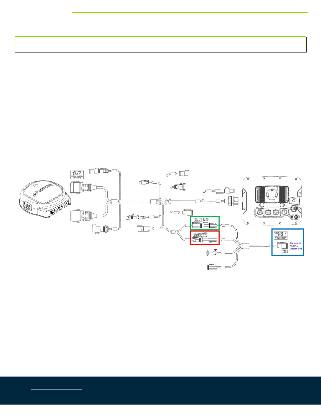
3.1. CANbusInterfaceforTopconSystemswithoutanApollo
1. Securelymountthecontrolmodule(E01)inthecabofthesprayer.
2. ConnecttheISOCANLOOPconnectoroncableC40totheCAN1/ISOBUSconnectoronharnessAGA4700
(Figure1‐GreenBox).
3. ConnectthePOWERconnectoroncableC40totheSWITCHEDPOWERconnectoronharnessAGA4700
(Figure1‐RedBox).
4. Connectthe6‐pinDeutschplug(NORACECU)oncableC40totheCANbusRepeater(E08).(Figure1‐Blue
Box).
Figure1:CANbusInterfaceforTopconSystemswithoutanApollo

WWW.NORAC.CA
PRECISIONDEFINED
Page5
Visitwww.solutions.norac.caformoresystem
installationandtroubleshootinginfo.
3.2. CANbusInterfaceforTopconSystemswithanApollo
1. Securelymountthecontrolmodule(E01)neartheTopconApolloECU.
2. ConnecttheSWITCHBOXconnectoroncableC41totheSWITCHBOXconnectoronharness1009865‐01or
harness1009864‐01(Figure2‐GreenBoxes).
3. ConnectthePOWERconnector(receptacle)oncableC41totheSECTIONVALVEPOWERconnectoron
harness1009865‐01orharness1009864‐01(Figure2–RedBoxes).
4. ConnectthePOWERconnector(plug)oncableC41tothePOWERconnectoronharness1010282‐01
(Figure2–BlackBoxes).
5. ConnecttheDeutschplugoncableC41totheCANbusRepeater(E08).(Figure2‐BlueBox).
Figure2:CANbusInterfaceforTopconSystemswithanApollo

WWW.NORAC.CA
PRECISIONDEFINED
Page6
Visitwww.solutions.norac.caformoresystem
installationandtroubleshootinginfo.
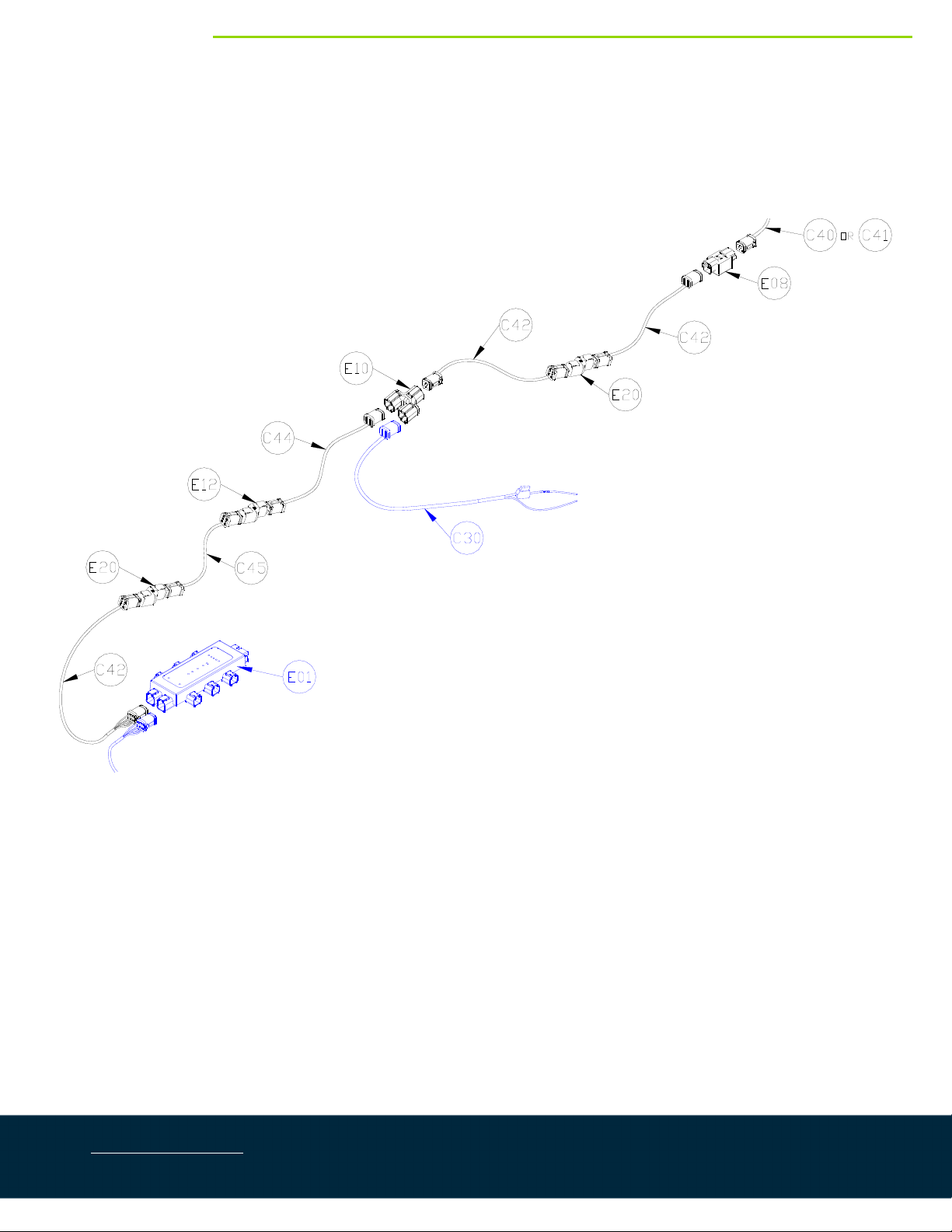
3.3. Self‐PropelledDisplayCablingInstallation
Figure3:DisplayCablingOverview
NOTE:Onlypartsshowninblackareincludedwiththispackage.Partsshowninblueareincludedwiththe
UC7™BoomHeightControlSystem.
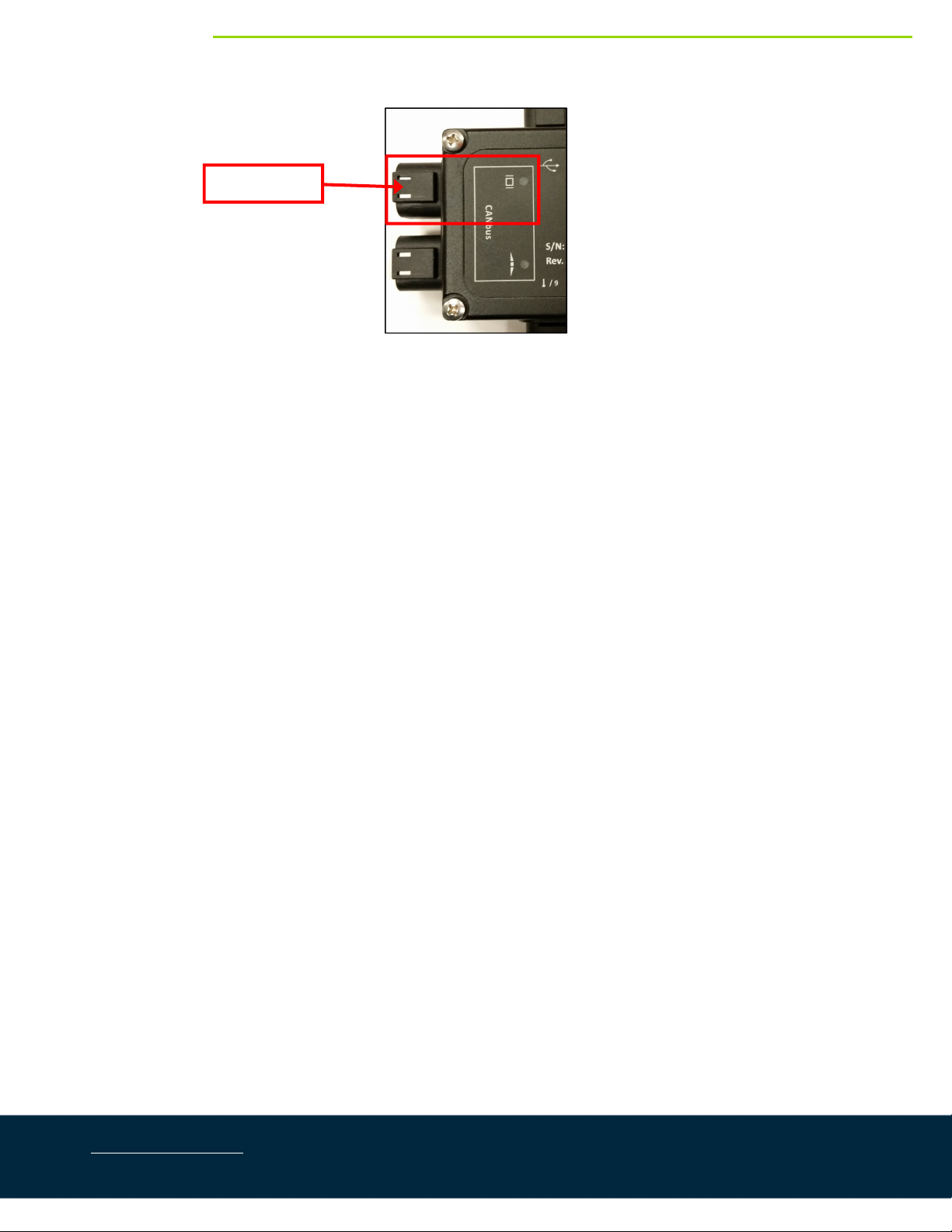
1. ConnectcableC42tothe6‐pindisplaybusconnectorontheHCM1(Figure4).
Figure4:DisplayBusLocation
2. ConnectcableC42tocableC43witha2‐waycouplerwithterminator(E20).The2‐waycouplerwith
terminatorisWHITE.
3. RoutecableC43intothecab.Connecttothe3‐waycoupler(E10).
DisplayBus

WWW.NORAC.CA
PRECISIONDEFINED
Page7
Visitwww.solutions.norac.caformoresystem
installationandtroubleshootinginfo.
4. Connectthepowercable(C30)tothe3‐waycoupler(E10).
5. ConnectthetwocablesC42togetherwitha2‐waycouplerwithterminator(E20).Connectoneendtothe
3‐waycoupler(E10).ConnecttheotherendtotheCANbusRepeater(E08).
6. ConnectcableC40(InstallationwithoutanApollo)orcableC41(InstallationwithanApollo)totheCANbus
Repeater(E08).
WWW.NORAC.CA
PRECISIONDEFINED
Page8
Visitwww.solutions.norac.caformoresystem
installationandtroubleshootinginfo.
3.4. PullTypeDisplayCablingInstallation
Ifinstallingonapulltypemachine,thepartslistedinSection1.2areneededandmustbeorderedseparately
fromthiskit.CableC43isnotusedforthistypeofinstallation.
Figure5:DisplayCablingOverview
NOTE:Onlypartsshowninblackareincludedwiththispackage.Partsshowninblueareincludedwiththe
UC7™BoomHeightControlSystem.
1. ConnectcableC42tothe6‐pindisplaybusconnectorontheHCM1(Figure6).
WWW.NORAC.CA
PRECISIONDEFINED
Page9
Visitwww.solutions.norac.caformoresystem
installationandtroubleshootinginfo.
Figure6:DisplayBusLocation
2. ConnectcableC45tocableC42witha2‐waycouplerwithterminator(E20).The2‐waycouplerwith
terminatorisWHITE.
3. RoutecableC45tothehitch.ConnectcableC45tocableC44witha2‐waycoupler(E12).The2‐way
couplerisBLACK.The2‐waycoupler(E12)willprovidethehitchdisconnect.
4. RoutecableC44intothecab.Connecttothe3‐waycoupler(E10).
5. Connectthepowercable(C30)tothe3‐waycoupler(E10).
6. ConnectthetwocablesC42togetherwitha2‐waycouplerwithterminator(E20).Connectoneendtothe
3‐waycoupler(E10).ConnecttheotherendtotheCANbusRepeater(E08).
7. ConnectcableC40(InstallationwithoutanApollo)orcableC41(InstallationwithanApollo)totheCANbus
Repeater(E08).
DisplayBus
WWW.NORAC.CA
PRECISIONDEFINED
Page10
Visitwww.solutions.norac.caformoresystem
installationandtroubleshootinginfo.
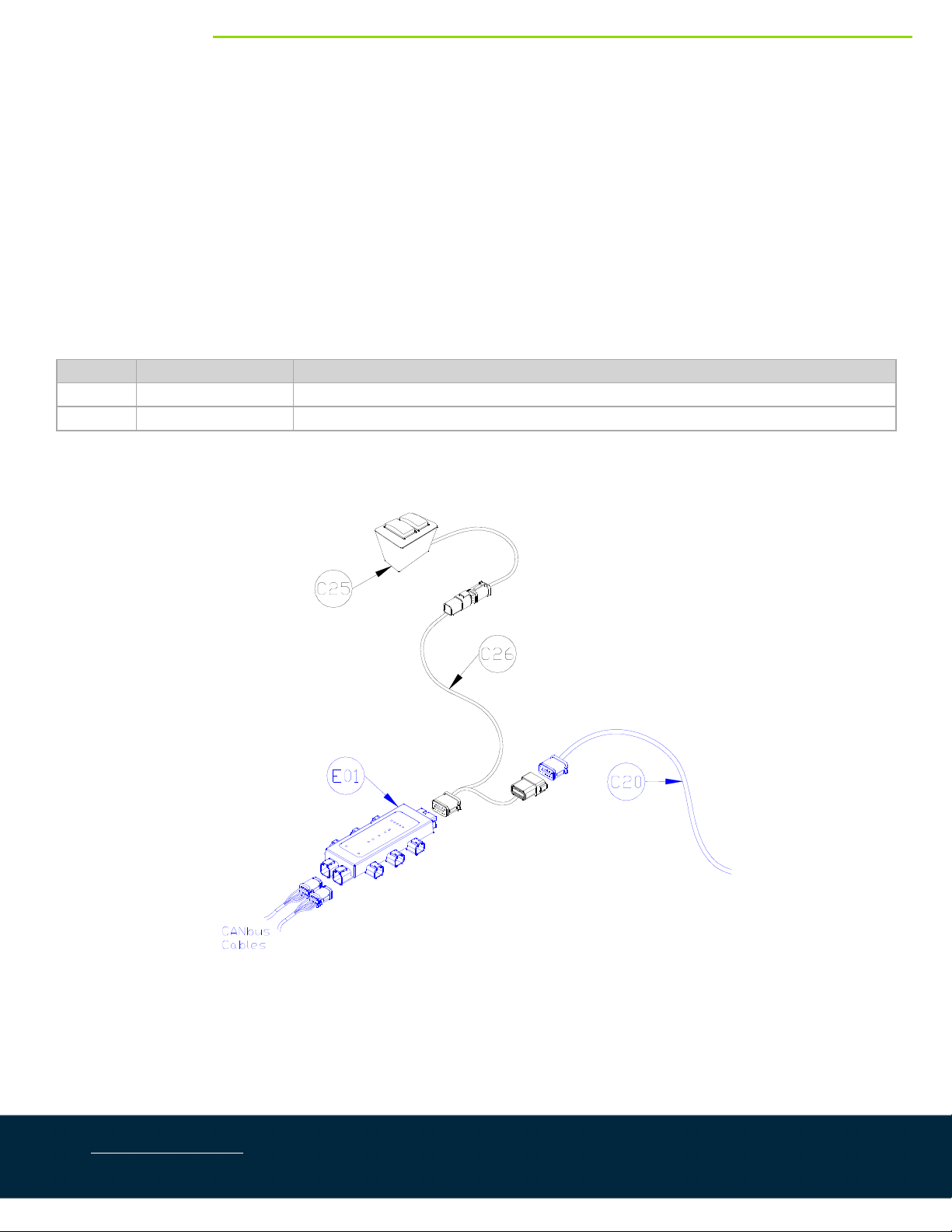
3.5. SwitchboxInstallation
1. DisconnectcableC20fromtheHCM1module(E01).
2. Insertthe12‐pinteeoncableC26betweentheHCM1moduleandcableC20.
3. Routetheotherendofcable26tothecabofthesprayer.
4. Installtheswitchbox(C25)insidethecab.ConnecttheswitchboxtocableC26.
5. IfcableC26isnotlongenough,anetworkcableandcouplerareavailablefororderfromNORAC.
ItemPartNumberName
C2743220‐03CABLENETWORK14AWG3M
E1243764NETWORKCOUPLER2‐WAY
* Some sprayer types may not use all the switch functions.
Figure7:SwitchboxInstallation
NOTE:Onlypartsshowninblackareincludedwiththispackage.Partsshowninblueareincludedwiththe
UC7™BoomHeightControlSystem.
WWW.NORAC.CA
PRECISIONDEFINED
Page11
Visitwww.solutions.norac.caformoresystem
installationandtroubleshootinginfo.
4CableSchematics
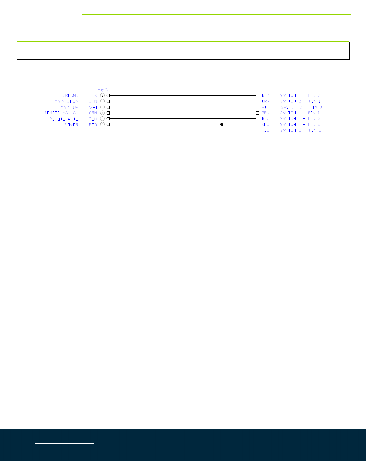
4.1. ItemC25:50250–Switchbox
WWW.NORAC.CA
PRECISIONDEFINED
Page12
Visitwww.solutions.norac.caformoresystem
installationandtroubleshootinginfo.
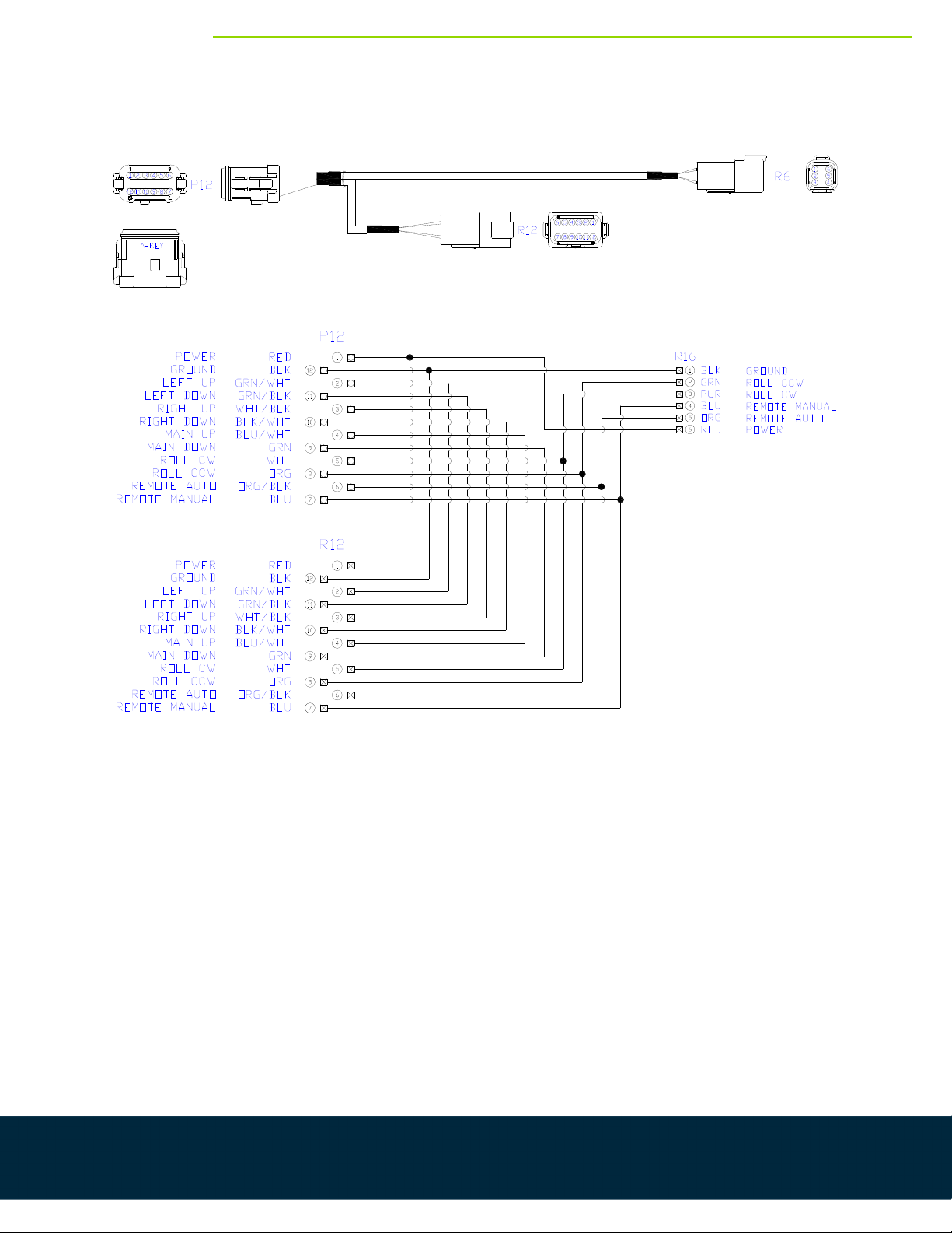
4.2. ItemC26:50140‐11–CableSwitchboxTee‐50250
WWW.NORAC.CA
PRECISIONDEFINED
Page13
Visitwww.solutions.norac.caformoresystem
installationandtroubleshootinginfo.
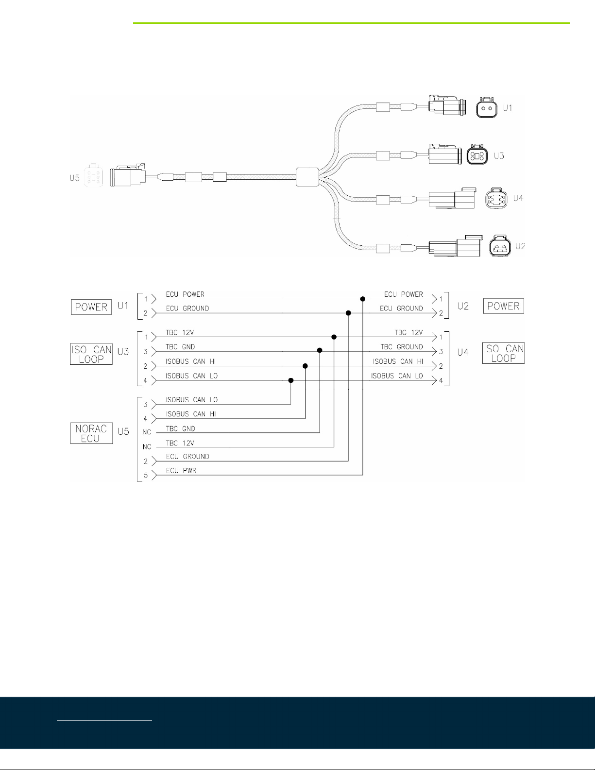
4.3. ItemC40:1015764‐01–CableTopconX25,X30CabInterface
WWW.NORAC.CA
PRECISIONDEFINED
Page14
Visitwww.solutions.norac.caformoresystem
installationandtroubleshootinginfo.
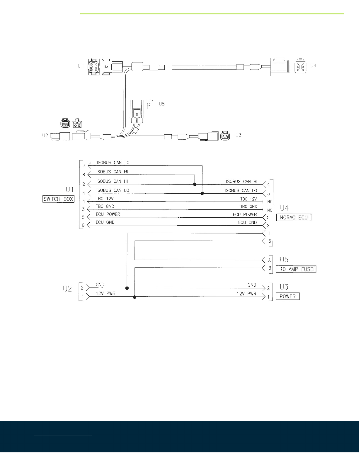
4.4. ItemC41:1015765‐01–CableTopconCM‐40Interface

WWW.NORAC.CA
PRECISIONDEFINED
Page15
Visitwww.solutions.norac.caformoresystem
installationandtroubleshootinginfo.
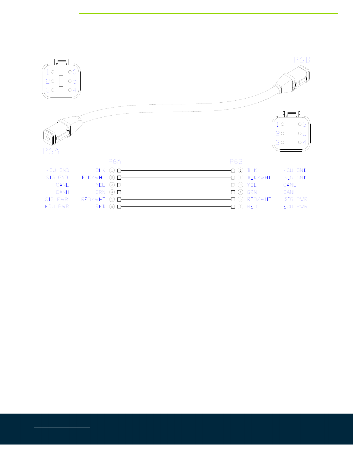
4.5. ItemC42:43220‐0.5‐CableNetwork14AWG–0.5m
WWW.NORAC.CA
PRECISIONDEFINED
Page16
Visitwww.solutions.norac.caformoresystem
installationandtroubleshootinginfo.
4.6. ItemC43:43220‐10‐CableNetwork14AWG–10m

WWW.NORAC.CA
PRECISIONDEFINED
Page17
Visitwww.solutions.norac.caformoresystem
installationandtroubleshootinginfo.
4.7. ItemC44:43220‐03‐CableNetwork14AWG–3m
This manual suits for next models
2
Table of contents


