Noraxon TeleMyo 2400T V2 User manual
TeleMyo 2400T V2®
Transmitter/ PC Card User Manual
P-2308TV2 Rev G (06-06-11)

Noraxon U.S.A., Inc. TeleMyo 2400T V2
© 2010, Noraxon U.S.A. Inc.
No part of this document may be copied, photographed, reproduced, translated, or reduced
to any electronic medium or machine readable form without the prior written consent of
Noraxon U.S.A. Inc.
Noraxon is a registered trademark of Noraxon U.S.A. Inc. All rights reserved. All other
company and product names contained herein may be trademarks or registered trademarks
of their respective companies and are sole property of their respected owners.
MNoraxon U.S.A. Inc.
15770 North Greenway-Hayden Loop, Suite 100
Scottsdale, AZ 85260
Tel: (480) 443-3413
Fax: (480) 443-4327
E-mail: [email protected]
Web Site: www.noraxon.com
PAuthorized European Representative:
Advena Ltd.
Thorne Widgery House,
33 Bridge Street, Hereford HR4 9DQ, UK
Telephone +44(0)1926 800153
+44(0) 845 094 3307
E-mail: [email protected]
Website: http://www.advenamedical.com
Skype: advenamedical
CE Mark: This symbol indicates the approval to market this product
in the European Community as certified by Notified Body #0344,
KEMA or #0473 AMTAC.
_____
P-2308TV2 Rev G (06-06-11)
1

Noraxon U.S.A., Inc. TeleMyo 2400T V2
Table of Contents
Icons and Symbols................................................................................................................................................3
TeleMyo 2400T Introduction ...............................................................................................................................4
TeleMyo 2400T Setup..........................................................................................................................................4
TeleMyo 2400T Components...............................................................................................................................4
A. Installing the Network Adapter...............................................................................................................7
B. Installing the Cisco Drivers .....................................................................................................................7
Driver Instructions for the Cisco Card Pictured Here.................................................................................10
C. Installing the Noraxon to Aironet Protocol...........................................................................................11
D. Installing the AEGIS Protocol (Necessary ONLY if you have the Cisco card with the Gold plate)....14
E. Configuring the Wireless Card in Windows XP ...................................................................................16
F. Setting the SSID in the Cisco Aironet Utilities.....................................................................................18
G. Setting up the TeleMyo 2400T in MyoResearch XP.............................................................................24
Controls and Displays.........................................................................................................................................27
Front Panel .................................................................................................................................................27
1. Status Indicator...........................................................................................................................27
2. Battery Charge Indicator.............................................................................................................28
3. Battery Charger Connector.........................................................................................................28
4. On/Off (Recharge) Switch..........................................................................................................28
5. Antenna Connector.....................................................................................................................28
Left Side.....................................................................................................................................................28
1. Sync Input Connector.................................................................................................................28
2. EMG Active Lead Connectors 1,3,5 and 7.................................................................................29
Right Side...................................................................................................................................................29
1. Sync Output Connector...............................................................................................................29
2. EMG Patient Lead Connectors 2,4,6 and 8.................................................................................29
3. External Battery Input.................................................................................................................29
Back Side....................................................................................................................................................30
1. Unit Number...............................................................................................................................30
2. Radio Channel ............................................................................................................................31
Status and Pre-Measurement Checks .................................................................................................................32
Establishing Measurement..................................................................................................................................33
Charging the battery ...........................................................................................................................................38
Radio Considerations..........................................................................................................................................39
Use of Disposable Electrodes.............................................................................................................................40
TeleMyo 2400T Cable and Accessory Connection/Disconnection....................................................................41
Maintenance .......................................................................................................................................................43
Cleaning .............................................................................................................................................................43
Technical Specifications.....................................................................................................................................44
Technical Description.........................................................................................................................................45
Transport and Storage.........................................................................................................................................45
Diagrams ............................................................................................................................................................46
Schematics and Parts List...................................................................................................................................47
Appendix A: Installing the PCMCIA Card Software for Windows 98 Users ....................................................48
Appendix B: Establishing a Measurement in MyoResearch or MyoClinical.....................................................50
_____
P-2308TV2 Rev G (06-06-11)
2

Noraxon U.S.A., Inc. TeleMyo 2400T V2
_____
Icons and Symbols
The following international icons and symbols are found on the TeleMyo 2400T enclosures. Their meaning is
described below.
0344
CE Mark: This symbol indicates the approval to market this
product in the European Community as certified by Notified Body
#0344, KEMA.
Non Ionizing Radiation: This symbol indicates that the device
generates radio frequency energy during operation.
Type B Input: This symbol indicates that the transmitter signal
input connections have a level B classification for protection against
electric shock. The inputs are not intended for use with AC line
powered equipment unless additional isolation measures are utilized.
Attention: This icon alerts the user to important information.
Carefully read and understand all sections of this document
displaying this symbol.
!
P-2308TV2 Rev G (06-06-11)
3

Noraxon U.S.A., Inc. TeleMyo 2400T V2
TeleMyo 2400T Introduction
The TeleMyo 2400T is the latest generation of Noraxon telemetry products. Each transmitter can
accommodate eight (8) channels of any combination of sEMG and a variety of analog signals. Multiple
transmitters can be coupled together to provide additional channels. The active electrode leads use
Noraxon’s patented signal processing technology to provide clear, consistent, and reliable data. The
TeleMyo 2400T System operates as an IEEE 802.11b wireless local area network. Communication is bi-
directional, using an internationally accepted direct sequence spread spectrum 2.4GHz radio channel.
The 2400T transmitter/PC Card combination allows the user to collect data using only two small
components and a computer. Once acquired, all data remains in a digital format. An optional receiver unit,
the TeleMyo 2400R, is available for users who require data in an analog format.
TeleMyo 2400T Setup
Step #1 – UNPACK ALL ITEMS AND CHECK INVENTORY
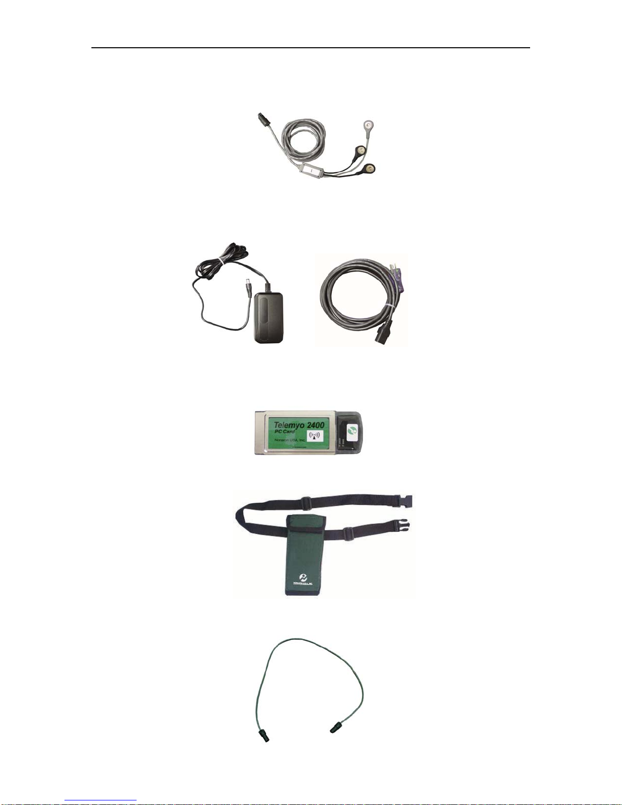
The following items should be included with the TeleMyo 2400T transmitter (see following figures).
1. TeleMyo 2400T transmitter device
2. Detachable antenna
3. EMG patient leads – (Number of leads depends on number of channels purchased)
4. Battery charger with country specific power cord
5. Noraxon Wireless PC LAN card device and software on CD
6. Transmitter carrying case with waist belt
7. Transmitter-to-transmitter Sync cable (Only used on multi-transmitter systems)
TeleMyo 2400T Components
1. TeleMyo 2400T V2 transmitter with antenna
P-2308TV2 Rev G (06-06-11)
4
Noraxon U.S.A., Inc. TeleMyo 2400T V2
2. EMG Active Lead (Quantity depends on number of channels desired)
3. Battery Charger Power Source with detachable country specific power cord
4. Noraxon Wireless LAN Card
5. Transmitter Carrying Case
6. Transmitter- to-transmitter Sync Cable (Only provided with systems over (8) channels)
P-2308TV2 Rev G (06-06-11)
5
Noraxon U.S.A., Inc. TeleMyo 2400T V2
Step #2 – PREPARING THE TRANSMITTER
1. The TeleMyo 2400T transmitter was supplied with a detachable antenna. If not already attached,
locate the transmitter antenna and its insulating rubber O-ring. Place the rubber O-ring around the
antenna receptacle on the transmitter. Next, screw the antenna to the transmitter to keep the O-ring in
place. Tighten the nut on the antenna to ensure a good connection.
2. Place the transmitter into the carrying case.
3. Remove the protective caps covering the input channel connectors. Keep these covers in a secure
place for future use. Plug the numbered EMG active leads into their respective mating end on the
TeleMyo 2400T transmitter. The numbers on the active leads should match the numbers on the
transmitter enclosure. Please note that there is one additional snap on the active lead labeled “1”. This
extra snap provides an electrical reference to the subject. One three-snap lead is required for each
transmitter used, i.e. one for every 8 channels used.
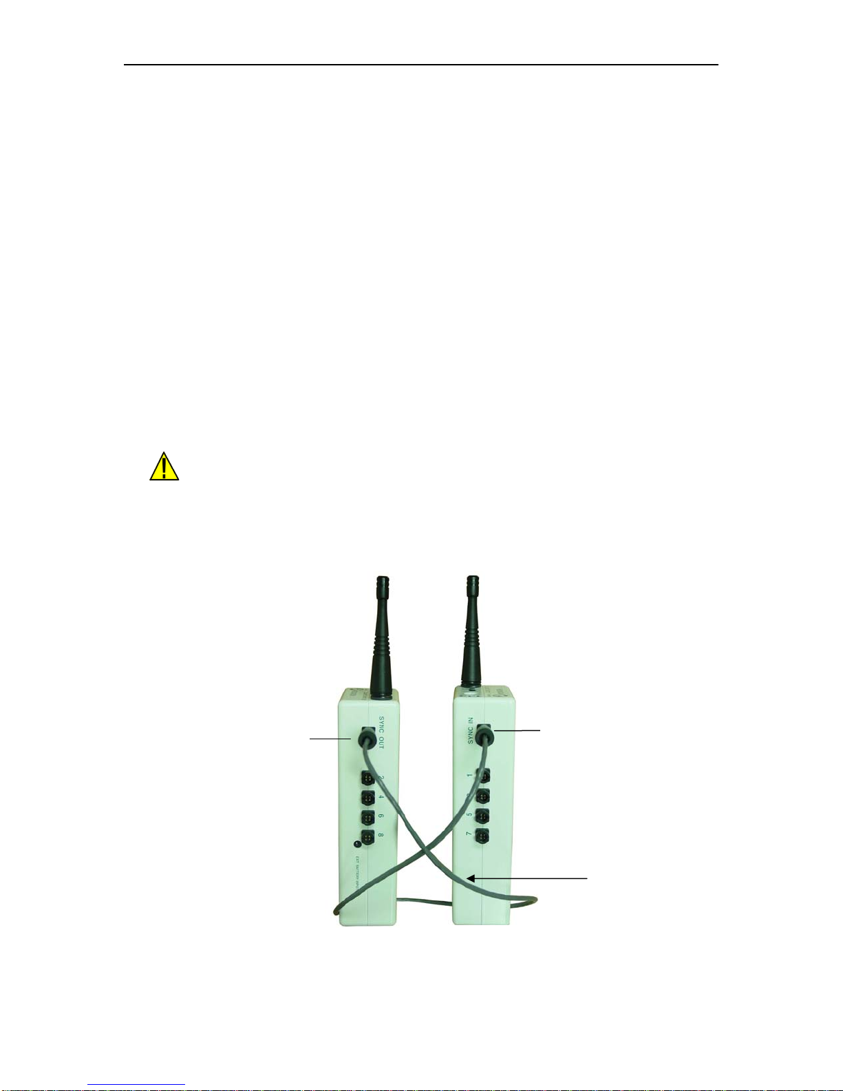
4. If using a multi-transmitter system (more than 8 channels), connect the transmitter-to-transmitter Sync
cable from the Sync Out connector on transmitter 1 to the Sync In connector on transmitter 2, then
Sync Out on transmitter 2 to Sync In on transmitter 3. Continue in this method until all transmitters
are connected together. No connection to the Sync In connector on transmitter 1 is necessary. See
illustration below.
All transmitter-to-transmitter Sync cable connections and disconnections
must be made before attaching EMG leads to the patient. Connecting and
disconnecting the transmitter-to-transmitter Sync cable when the patient is
connected can expose the patient to a shock hazard.
Sync Cable (18 in / 45.72 cm)
Sync In
Sync Out
Transmitter 1 Transmitter 2
P-2308TV2 Rev G (06-06-11)
6

Noraxon U.S.A., Inc. TeleMyo 2400T V2
Step #3 INSTALLING THE PCMCIA CARD SOFTWARE for Windows XP and
MyoResearch XP
Refer to Appendix A if you are using Windows 98 and/or MyoResearch.
NOTE: Due to the variety of Windows XP versions, there may be some slight inconsistencies in these
directions.
A. Installing the Network Adapter
1. With your computer turned off, insert the Noraxon Wireless PC LAN Card (Cisco Card) into an open
PCMCIA slot on your computer. Windows XP will automatically recognize the card.
B. Installing the Cisco Drivers
1. Insert the Cisco Card
into the Computer
2. Cancel out of “Add
New Hardware” Wizard
3. Insert MyoResearch XP
CD or the Driver CD that
was sent with the system.
4. Click on “Install Cisco
Drivers”
5. Select your card from
the two shown on the
screen.
NOTE: The
distinguishing factor is
the gold colored strip on
the bottom of the card in
the second picture.
P-2308TV2 Rev G (06-06-11)
7
Noraxon U.S.A., Inc. TeleMyo 2400T V2
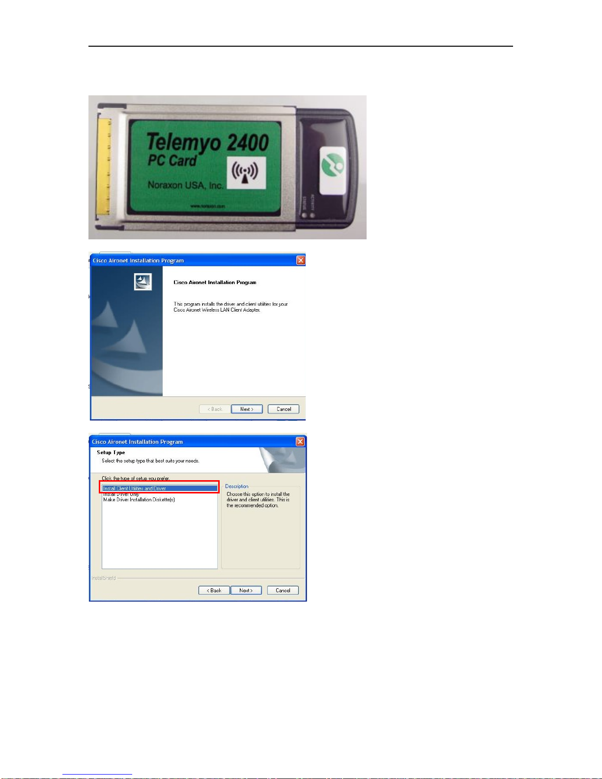
Driver Instructions for the Cisco Card Pictured Here:
Instructions continued
from above.
6. Introduction Screen for
the Aironet Desktop
Utility. Click next.
7. Choose “Install Client
Utilities and Driver” and
click Next.
P-2308TV2 Rev G (06-06-11)
8

Noraxon U.S.A., Inc. TeleMyo 2400T V2
6. You do not need to
install the Site Survey
Utility – leave the box
unchecked.
7. Use the default
directory or if desired
choose your own.
8. Select the program
folder – the default folder
should work.
P-2308TV2 Rev G (06-06-11)
9

Noraxon U.S.A., Inc. TeleMyo 2400T V2
9. Just before this screen
is a “Read Me” screen. It
explains the difference
between the Cisco
Aironet Desktop Utility
(ADU) and the Third
Party Tool.
10. Choose the Cisco
Aironet Desktop Utility
(ADU)
11. A message will appear
telling you it will install
the driver on your Cisco
card.
12. You will be instructed
that you computer needs
to be restarted.
Driver Instructions for the Cisco Card Pictured Here:
Instructions continued
from steps 1-5 above.
6. Choose installation
option and click next.
The program will
automatically load the
software and driver.
Screens will pop up
briefly letting you know
which step it is
performing.
P-2308TV2 Rev G (06-06-11)
10

Noraxon U.S.A., Inc. TeleMyo 2400T V2
C. Installing the Noraxon to Aironet Protocol
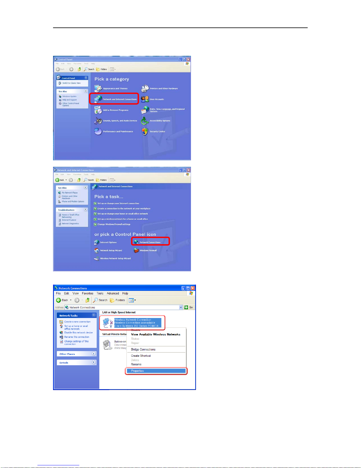
1. Open the Control Panel and click
“Network and Internet Connections”.
2. In the displayed window, click
“Network Connections”.
3. In the displayed window, find the
connection that corresponds to your
wireless LAN. Click it with the
right mouse button, then click
“Properties”.
P-2308TV2 Rev G (06-06-11)
11
Noraxon U.S.A., Inc. TeleMyo 2400T V2
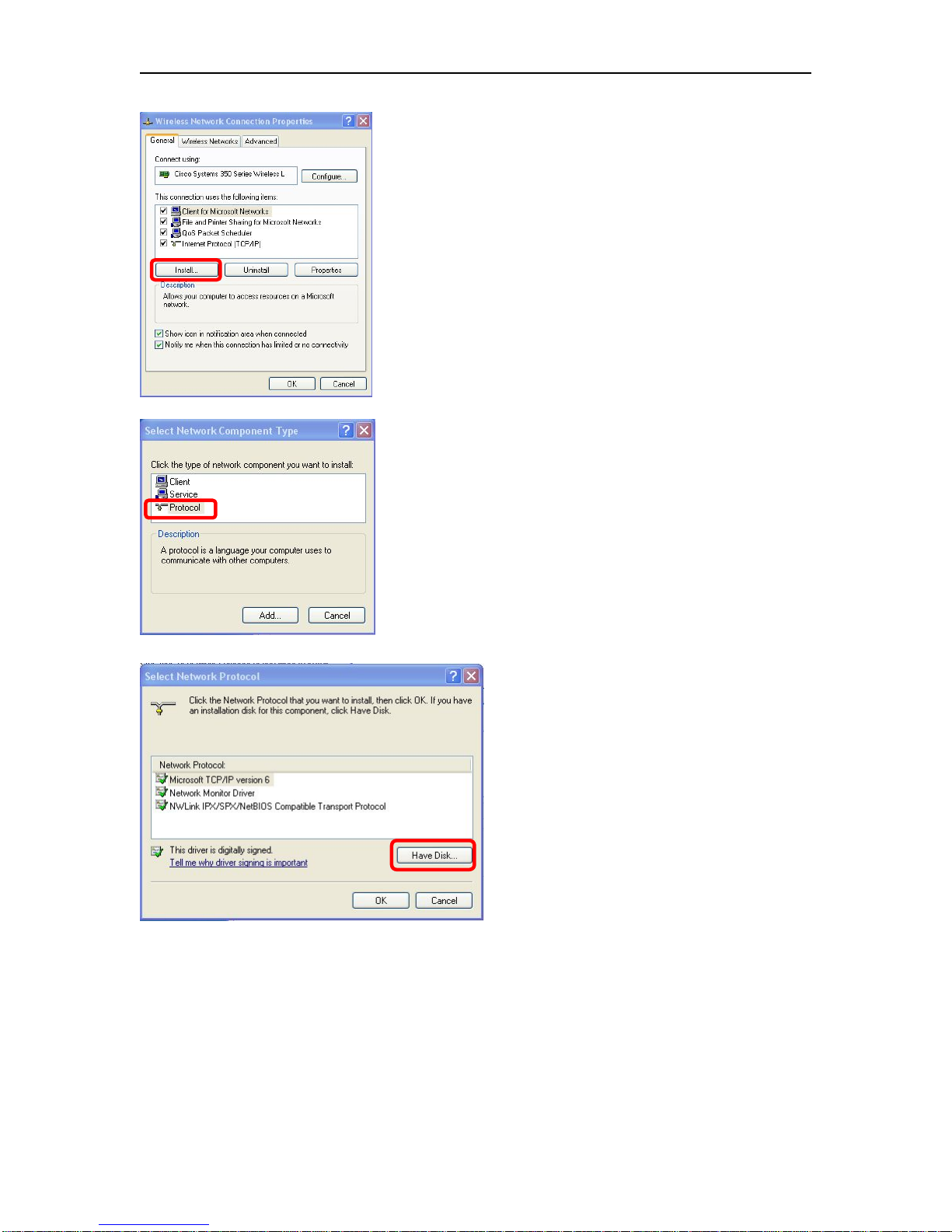
4. In the displayed dialog, click
“Install”.
5. In the displayed dialog, double-
click “Protocol”.
6. In the displayed dialog, click
“Have Disk”
P-2308TV2 Rev G (06-06-11)
12

Noraxon U.S.A., Inc. TeleMyo 2400T V2
7. In the displayed dialog, find the
directory where your Noraxon
wireless drivers are located on your
CD. You may be able to find the
directory by using the pull-down
menu or you may need to click
browse. If you click “Browse”, you
will be looking for your CD drive,
then the directory
“Drivers\Wireless”. (e.g.
“D:\Drivers\Wireless”), then click
“OK”.
8. If you selected the correct
directory, the following dialog will
appear. Double-click “Noraxon to
Aironet interface”. Close all dialogs
with OK. Confirm reboot if asked.
NOTE: It is safe to ignore the
warning “This driver is not digitally
signed.”
P-2308TV2 Rev G (06-06-11)
13
Noraxon U.S.A., Inc. TeleMyo 2400T V2
D. Installing the AEGIS Protocol (Necessary ONLY if you have the Cisco card with the Gold plate)
1. Open the Control Panel
and click “Network and
Internet Connections”.
2. In the displayed window,
click “Network
Connections”.
3. In the displayed window,
find the connection that
corresponds to your wireless
LAN. Click it with the right
mouse button, then click
“Properties”.
P-2308TV2 Rev G (06-06-11)
14

Noraxon U.S.A., Inc. TeleMyo 2400T V2
4. In the displayed dialog,
click “Install”.
5. In the displayed dialog,
double-click “Protocol”.
6. Select “Meetinghouse
Data Communication” for
the Manufacturer and
“AEGIS Protocol” for the
Network Protocol. and click
OK.
P-2308TV2 Rev G (06-06-11)
15

Noraxon U.S.A., Inc. TeleMyo 2400T V2
E. Configuring the Wireless Card in Windows XP
1. Open the Control Panel and click
“Network and Internet
Connections”.
2. In the displayed window, click
“Network Connections”.
3. In the displayed window, find the
connection that corresponds to your
wireless LAN. Click it with the
right mouse button, then click
“Properties”.
P-2308TV2 Rev G (06-06-11)
16

Noraxon U.S.A., Inc. TeleMyo 2400T V2
4a. In the displayed dialog, ensure
that the “Noraxon to Aironet
Interface” is checked and uncheck
all the other entries.
4b. NOTE: If you have the Gold
plated Cisco Card, check the
“AEGIS Protocol” also.
5. Select the “Wireless Networks”
tab. Uncheck “Use Windows to
configure my wireless network
settings.” Click OK.
4a 4b
P-2308TV2 Rev G (06-06-11)
17
Noraxon U.S.A., Inc. TeleMyo 2400T V2
F. Setting the SSID in the Cisco Aironet Utilities
If you have this Cisco Card, follow these instructions:
1. After rebooting your
computer, remove the Cisco
card and reinsert it. In the
lower right-hand corner of
your computer screen you
should see an icon that
resembles the icon used for
the Aironet Desktop Utility.
If you do not see this icon,
try removing and reinserting
your Cisco card again.
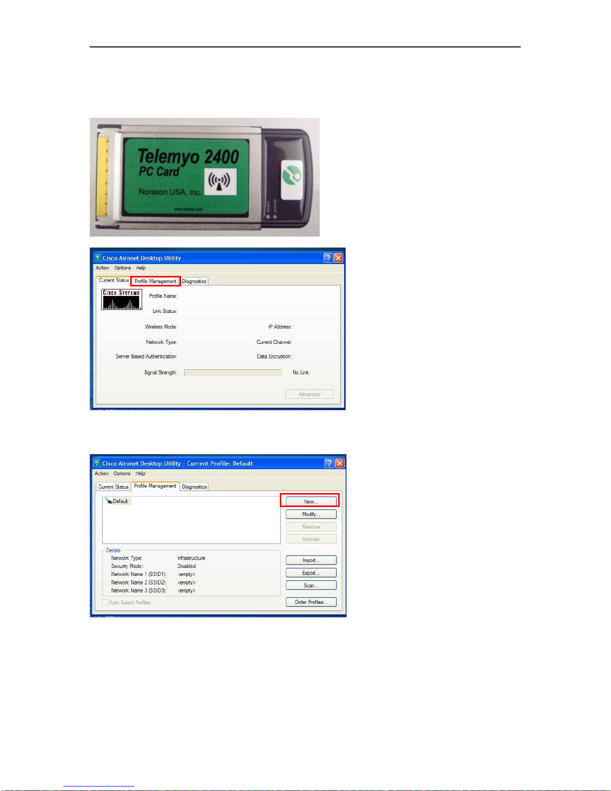
2. Double click on the
Aironet Desktop Utility icon.
It will open to this screen.
Click on the tab “Profile
Management”.
3. Click on “New” to add a
New profile.
P-2308TV2 Rev G (06-06-11)
18

Noraxon U.S.A., Inc. TeleMyo 2400T V2
4. Select the “General” tab
and choose a Profile Name.
The Client Name is usually
defaulted to the name of the
computer.
5. Enter the SSID1 as
TELEMYO. (It must be all
caps.)
6. Select the “Security” tab.
Choose “None” for the
Security options and click
OK.
7. Select the “Advanced” tab.
The “Transmit Power Level”
should be defaulted to
100mW.
8. Select “2.4 GHz 11Mbps”
for the “Wireless Mode”.
9. For the “Network Type”,
select “Ad Hoc” and choose
“Long Only”.
10. Select “Channel 1” and
then click OK.
P-2308TV2 Rev G (06-06-11)
19
Table of contents
Popular Computer Hardware manuals by other brands

Kystar
Kystar U3pro user manual

Icy Box
Icy Box IB-553 Series manual

ekwb
ekwb EK-DBAY DCP 2.2 INSTALLATION AND MOUNTING MANUAL

Lantronix
Lantronix N-FXE 02B Series user guide

Cytron Technologies
Cytron Technologies SmartDrive40 user manual

Addonics Technologies
Addonics Technologies AD5SAHPM-E installation guide


Dynacord
Dynacord DMM 4650 technical information

Advantech
Advantech SOM-5992 user manual

Moxa Technologies
Moxa Technologies CP-102E Quick installation guide

Lucid Technologies
Lucid Technologies MCP6004 user manual

Motorola
Motorola Expedience PCC-2510 Instructions for installing and using

CAMBRIONIX
CAMBRIONIX OEM-U8S user manual