Norcold N1090 Series User manual

© 2017 NORCOLD, INC. All rights reserved. Part No. / N° d’article / Artículo n.° 639687 Rev. A (08.17.2017)
Compressor Refrigerators
Service Manual
MODEL
N1090 Series
Improper installation,
adjustment, alteration,
service or maintenance
can cause personal
injury or property damage.
Refer to this manual. For
assistance or additional
information, contact a
qualified installer, service
agency, or the gas sup-
plier.
NOTICE
AVIS
AVISO
CAUTION
!
ATTENTION
!
ATTENTION
ATTENTION
!
ATENCIÓN
ATTENTION
!
DANGER
Une installation, un
ajustement, une
modification, une
réparation ou un entretien
incorrect peut causer
des blessures ou des
dommages matériels.
Consultez ce manuel.
Pour obtenir de l’aide ou
d’autres renseignements,
contactez un installateur
qualifié, un service
de réparation ou le
fournisseur de gaz.
NOTICE
AVIS
AVISO
CAUTION
!
ATTENTION
!
ATTENTION
ATTENTION
!
ATENCIÓN
ATTENTION
!
DANGER
ATTENTION
!
DANGER
Las alteraciones o los
procedimientos incorrectos
de instalación, ajuste,
servicio o mantenimiento
pueden causar lesiones
a personas o daños
materiales. Consulte este
manual. Para recibir ayuda
o información adicional,
póngase en contacto con
un instalador capacitado,
empresa de servicios
o proveedor de gas.
ATTENTION
!
PELIGRO

2
Refrigerator Service Manual / Manuel d'entretien du réfrigérateur / Manual de servicio del refrigerador
Model N1090/ Modèle N1090/ Modelo N1090
CONTENTS
SAFETY ...................................................................................2
SPECIFICATIONS....................................................................3
Internal Capacities.......................................................................3
Controls........................................................................................3
Off-Level Operating Limits...........................................................3
DC Power..................................................................................... 3
Current Draw................................................................................ 3
Typical DCAmperage Draw @ Nominal 12 VDC.......................3
Energy Consumption...................................................................3
Climate Class...............................................................................3
EXPLODED VIEW....................................................................4
DIAGNOSTICS.........................................................................5
Diagnostic Pre-Checks.........................................................................5
Self-Test Diagnostics............................................................................5
Connecting the LED.....................................................................5
Reading the LED.......................................................................... 6
DIAGNOSTIC SYMPTOM CHART..........................................7
TROUBLESHOOTING.............................................................9
Troubleshooting - TestA, Battery Cut-Out............................................ 9
Troubleshooting - Test B, Fan Cut-Out............................................... 10
Troubleshooting - Test C, Motor Start Error ........................................11
Troubleshooting - Test D, Minimum Motor Speed Error .....................12
Troubleshooting - Test E, Electronic UnitThermal Cut-Out ..............13
Troubleshooting - Test F, Not Cooling, Not Turning On......................14
Troubleshooting - Test G, Refrigerator Gets Too Cold........................15
Troubleshooting - Test H, Refrigerator Builds Frost Inside ................16
Troubleshooting - Test I, Runs but Does Not Cool .............................17
Troubleshooting - Test J, Will Not Run On DC Power ........................18
TEST UNIT.............................................................................19
Wiring Pictorial....................................................................................19
REMOVE AND INSTALL .......................................................19
Remove Unit..............................................................................19
Install Unit..................................................................................19
SAFETY
Read this manual carefully and understand the contents before
working on the refrigerator.
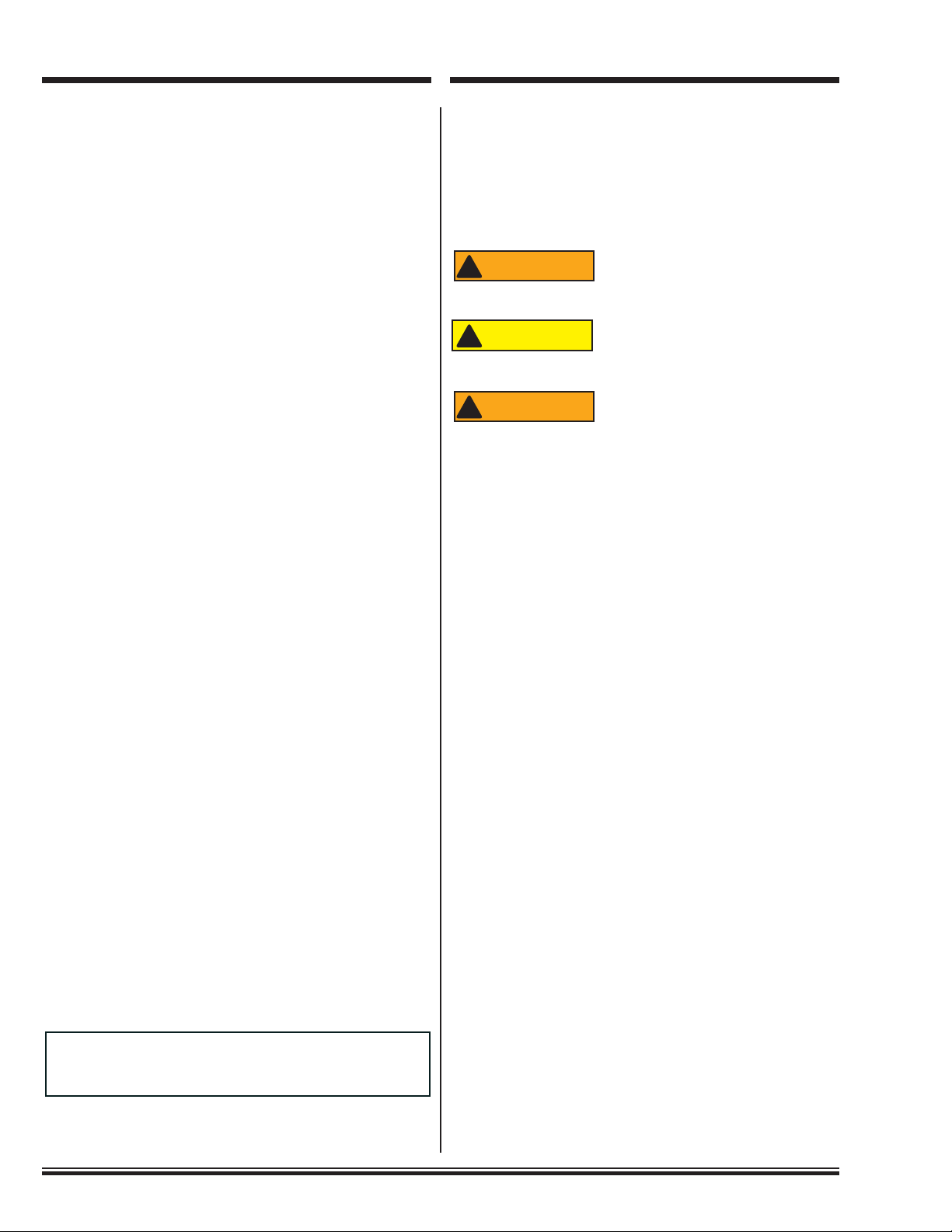
Be aware of possible safety hazards when you see the safety
alert symbol on the refrigerator and in this manual. A signal
word follows the safety alert symbol and identifies the danger
of the hazard. Carefully read the descriptions of these signal
words to fully know their meanings. They are for your safety.
This signal word means a hazard, which if
ignored, can cause dangerous personal injury,
death.
This signal word means a hazard, which if
ignored, can cause small personal injury or
much property damage.
The storage of flammable materials behind or
around the refrigerator creates a fire hazard.
Do not use the area behind the refrigerator to
store anything, especially flammable materials
(gasoline, cleaning supplies, etc.).
■Acircuit overload can result in an electrical fire if the wires and/or fuses
are not the correct size. Use only the wire and fuse sizes as written in
the “Installation Manual.”
■Incorrect installation, adjustment, change to, or maintenance of this
refrigerator can cause personal injury, property damage, or both. Have
service and maintenance work done by your dealer or by an authorized
Norcold Service Center.
■Disconnect the DC power source before doing any maintenance work on
the refrigerator.
■Do not bypass or change the refrigerator’s electrical components or
features.
■Do not spray liquids near electrical outlets, connections, or the refrigera-
tor components. Many liquids are electrically conductive and can cause
a shock hazard, electrical shorts, and in some cases fire.
■Do not touch the evaporator or other metal parts inside the refrigerator
cabinet with wet hands because they can freeze to the refrigerator.
■The rear of the refrigerator has sharp edges and corners. To prevent cuts
or abrasions when working on the refrigerator, be careful and wear cut
resistant gloves.
■When you discard an appliance, remove all doors to prevent accidental
entrapment and suffocation.
■At regular intervals, make sure that the refrigerator vent areas and the
air pathway between the vents is completely free from any flammable
material or blockage. After a period of storage, it is especially important
to check these areas for any flammable material or blockage caused by
animals and insects.
■Risk of fire or explosion.Aflammable refrigerant (R600a) is used. To be
repaired only by trained Service personnel. Do not puncture refrigerant
tubing.
■Red painted tubing indicates that a flammable refrigerant is present.
ATTENTION
!
WARNING
CAUTION
!
ATTENTION
!
WARNING
FIGURES
Fig. 1: Model N1090.............................................................................4
Fig. 2 - LED and connectors ................................................................5
Fig. 3 - LED, connectors and control module.......................................5
Fig. 3.1 -Attach Blade Connectors.......................................................5
Fig. 3.2 - Disconnect 12 VDC...............................................................6
Fig. 3.3 - Connect BladeAdapter..........................................................6
Fig. 3.4 - Connect LED.........................................................................6
Fig. 3.5 - LED connection to control module.........................................6
Fig. 4: Wiring Pictorial.........................................................................19
La version française commence à la page 21.
La versión en español comienza en la página 41.

Refrigerator Service Manual / Manuel d'entretien du réfrigérateur / Manual de servicio del refrigerador
3
N1090 Models / Modèles N1090 / Modelos N1090
SPECIFICATIONS
Internal Capacities
Total Capacity ------------------------------------------------------------------------------------ 3.2 cubic feet
Freezer Volume ---------------------------------------------------------------------------------- 0.2 cubic feet
Controls
On - Off / Temperature Setting / Night Mode switches -------------------------------------- Electronic
Temperature Setting Range----------------------------------------------------------1=Cold to 5=Coldest
Temperature Sensing Device --------------------------------------------------------------------- Thermistor
Off-Level Operating Limits
Side-to-Side ----------------------------------------------------------10 degrees maximum at refrigerator
Front-to-Back --------------------------------------------------------10 degrees maximum at refrigerator
DC Power
Voltage Requirements -----------------------------------------------------------------------10.4 - 15.4 VDC
Fuse/Breaker - 12 VDC -------------------------------------------------------------15 A - Slow Blow Type
Current Draw
Day Mode-------------------------------------------------------------------------------------------------------- 4 A
Night Mode ------------------------------------------------------------------------------------------------------2 A
Minimum (cut-out) ------------------------------------------------------------------------------------ 10.4 VDC
Restart (cut-in)----------------------------------------------------------------------------------------- 11.7 VDC
Typical DC Amperage Draw @ Nominal 12 VDC
Startup----------------------------------------------------------------------------------------------------------5.0 A
Stabilization ---------------------------------------------------------------------------------------------------4.0 A
Energy Consumption
Day Mode--------------------------------------------------------------------------------------- 0.40 kWh / 24 h
Night Mode ------------------------------------------------------------------------------------- 0.30 kWh / 24 h
Climate Class
Day Mode----------------------------------------------------------------------------------- ST (60°F to 100°F)
Night Mode ------------------------------------------------------------------------------------ N (60°F to 90°F)

Refrigerator Service Manual / Manuel d'entretien du réfrigérateur / Manual de servicio del refrigerador
4
N1090 Models / Modèles N1090 / Modelos N1090
EXPLODED VIEW
NO. DESCRIPTION NO. DESCRIPTION
1 Vegetable Bin (2x) 18 Condenser Fan
2 Drip Tray 19 Control Module
3 Bracket 20 Air Duct
4 Door Bin 21 Power Cord
5 Clip Shelf Large (2x) 22 Control PCB
6 Shelf Food Retainer 23 Control Housing
7 Shelf Small 24 Control Housing Bracket (2x)
8 Clip Shelf Small 25 Hinge Plate Upper
9 Plate 26 Hinge Pin Upper
10 Door Handle Lower 27 Hinge Spring
11 Door Lock Plate 28 Cabinet Door
12 Door Handle Upper 29 Panel Retainer Lower
13 Identification Label (not shown) 30 Hinge Pin Lower
14 Cap (4x) 31 Hinge Plate Lower
15 Screw (4x) 32 Freezer Door
16 Thermistor Cover 33 Bottle Retainer
17 Thermistor 34 Door Bin (2x)
NOR000705A
Fig. 1: Model N1090
The parts shown are identified for the purpose
of assisting you with diagnostic procedures.
Visit www.thetford.com to view the full service
parts list and order parts.
NOTICE

5
Refrigerator Service Manual / Manuel d'entretien du réfrigérateur / Manual de servicio del refrigerador Modelos N1090 / Modèles N1090 / Modelos N1090
Diagnostic Pre-Checks
Before performing detailed diagnostics inspect for the
following:
1. Make sure the refrigerator is turned ON.
2. Make sure the door is closed and sealing correctly.
3. Make sure the refrigerator is correctly installed and that
the vents are not blocked.
There may be more than one over current
device in the refrigerator supply circuit.
Be sure to check both the RV and refrigera-
tor.
4. Make sure the vehicle fuse or circuit breaker is intact.
5. Make sure the ambient temperature is not unusually high
(more than 110° F. / 43° C.). Maximum ambient tempera-
ture is 131°F.
6. Make sure that the air circulation inside the refrigerator
is not decreased by foods or by shelves that are covered
with plastic, paper, etc.
7. Make sure the freezer is defrosted.
8. Bypass the thermostat by disconnecting the wires and
installing jumper wire in place of thermostat. If unit works
replace thermostat.
After these pre-checks, if the refrigerator does not operate:
9. Remove unit from its enclosure; refer to "Remove and
Install" section.
10.Perform the diagnostics outlined in the "Self-Test Diag-
nostics" section.
11. If the self-test diagnostic tests do not reveal an error code,
refer to the "Diagnostic Symptom Chart."
Self-Test Diagnostics
The unit’s control module is equipped with a self-test
diagnostic function which can be read using a light emitting
diode (LED). To access the error codes displayed in the
control module, you will need the items in Fig. 2. Refer to Fig.
3 - Fig. 3.5 for diagnostic instructions.
Fig. 2 - LED and connectors
NOTICE
NOR00000033A
A
B
A2
A1
Reference Description
A (1x) 10 mALED with wire leads
A1 (1x) 1/4 inch push-on female connectors (Black)
A2 (1x) 1/4 inch push-on female connectors (Red)
B 1/4 inch adapter with one (1) female and two (2) male
connections
C 12 VDC Input Wire
D 12 VDC Terminal "+"
E Control Module
F Terminal "D"
Fig. 3 - LED, connectors and control module
Do not leave jumpers in place for normal
operation.
The control module may vary in appearance,
but the procedure is identical regardless of
model.
Connecting the LED
Refer to Fig. 2, and Figs. 3.1-3.5
1. Attach the two (2) female blade connectors (A1, A2) to
the wire leads of the LED (A).
Fig. 3.1 - Attach Blade Connectors
2. On the control module (E), disconnect the 12 VDC input
wire (C) from the "+" terminal (D).
NOTICE
A
A2
A1
1
1
_
+
+
F
D
C
P
T
12/24 Vdc
E
CD
2
2
DIAGNOSTICS

6
Refrigerator Service Manual / Manuel d'entretien du réfrigérateur / Manual de servicio del refrigerador
Model N1090/ Modèle N1090/ Modelo N1090
Fig. 3.2 - Disconnect 12 VDC
3. Connect the blade adapter (B) to the "+" (D) terminal.
Fig. 3.3 - Connect Blade Adapter.
4. Connect the black LED wire (A1) to terminal "D" (F);
connect the red LED wire (A2) to the one side of blade
(B).
Fig. 3.4 - Connect LED
5. Connect the 12 VDC input wire (C) to the other side of
adapter blade (B).
Fig. 3.5 - LED connection to control module
Reading the LED
If an error code is activated in the control module and the LED
is connected, it will flash a number of times. The number of
flashes will depend on what error was recorded. Each flash
will last 1/4 second and after the code is flashed there will be a
delay, then the code will repeat.
Write down all error codes; then refer to "Self-Test Diagnostic
Chart."
_
+
+
F
D
C
P
T
12/24 Vdc
D
B
3
3
_
+
+
F
D
C
P
T
12/24 Vdc
A2
A1
B
F
4
4
_
+
D
C
P
T
12/24 Vdc
F
A
C
5
5
NOR000019A-5c
C
B

Refrigerator Service Manual / Manuel d'entretien du réfrigérateur / Manual de servicio del refrigerador
7
N1090 Models / Modèles N1090 / Modelos N1090
DIAGNOSTIC SYMPTOM CHART
LED Flash Codes Possible
Symptoms Possible Cause Action to Take
One ash 1/4 seconds, pause, repeat.
BATTERY
cuts out The voltage is outside the cut out setting. Perform TestA. Refer to page
9.
Two 1/4 second ashes, pause, repeat.
FAN
cuts out The fan electrical load exceeds more than 1.0 amp. Perform Test B. Refer to page
10.
Three 1/4 second ashes, pause, repeat.
MOTOR
will not start The rotor is blocked or the differential pressure in the
refrigeration system is too high ( >5 bar). Perform Test C. Refer to page
11.
NotApplicable MOTOR
will not run • Blown fuse in DC circuit
• Undersized wiring to refrigerator, minimum #12
gauge wire required, refer to Installation Manual
• Partially discharged battery, voltage below 11.3
VDC at compressor module
• High resistance (voltage drop) in supply circuit
Perform Test J. Refer to page 18.
Four 1/4 second ashes, pause, repeat.
MOTOR
will not maintain minimum
speed
If the refrigeration system is too heavily loaded,
the motor can not maintain minimum speed (1850
rpm).
Perform Test D. Refer to page
12.
Five 1/4 second ashes, pause, repeat.
MOTOR
periodically cuts out If the refrigeration system has been too heavily load-
ed or the ambient temperature is high, the electronic
unit will run too hot.
Perform Test E. Refer to page
13.
Not Applicable NOT COOLING
not turning on • Faulty thermostat
• Power to control module
• Faulty wire from control module to compressor
• Faulty control module
• Faulty Compressor
Perform Test F. Refer to page 14.
Not Applicable NOT COOLING
Runs, but does not cool
properly
• Bad capillary tube position
• Faulty thermostat
• Faulty control module
Perform Test I. Refer to page 17.
Not Applicable NOT COOLING
compressor starts but shuts
off directly
Overheated due to high ambient temperature Turn off refrigerator for one (1)
hour, vent the vehicle, change
refrigerator to day mode.
Not Applicable NOT COOLING
compressor does not run
at all
• Battery voltage is too low. Recharge the battery.
• Start delay of one (1) minute. Wait one (1) minute.
• Overheated due to high ambient temperature. Turn off refrigerator for one (1)
hour, vent the vehicle, change
refrigerator to day mode.
• Vehicle fuse has blown. Check fuse rating, replace with
15Afuse.
NotApplicable NOT COOLING Ventilation openings are completely or partially
blocked. Clean or remove the blockage
The door is not properly closed. Close the door, make sure the
seals are in good condition.
There is more than 0.12 inch ice on evaporator Defrost the refrigerator, make sure
the seals are in good condition.
Overheated due to high ambient temperature. Turn off refrigerator for one (1)
hour, vent the vehicle, change
refrigerator to day mode.
Not Applicable NOT COOLING
Compressor runs continu-
ously
Go to a Service Center.

Refrigerator Service Manual / Manuel d'entretien du réfrigérateur / Manual de servicio del refrigerador
8
N1090 Models / Modèles N1090 / Modelos N1090
Diagnostic Symptom Chart, cont’d.
LED Flash Codes Possible
Symptoms Possible Cause Action to Take
NotApplicable GETS TOO COLD • Bad capillary tube position
• Faulty thermostat
• Faulty control module
Perform Test G. Refer to page
15.
NotApplicable FROST
Builds frost inside • Door not closed
• Damaged door gasket
• Air leak at foam plug
Perform Test H. Refer to page
16.
NotApplicable FREEZER
is not freezing. Interior temperature of vehicle is lower than 61° F Raise the temperature inside the
vehicle and / or select a higher
refrigerator temperature setting to
minimum level 4.
NotApplicable Unit is too loud. The refrigerator is in day mode. Change to night mode if tempera-
ture is below 86° F.

9
Refrigerator Service Manual / Manuel d'entretien du réfrigérateur / Manual de servicio del refrigerador Modelos N1090 / Modèles N1090 / Modelos N1090
TROUBLESHOOTING
Troubleshooting - Test A, Battery Cut-Out
Verify:
■Battery charging equipment of the vehicle is operational.
■AC/DC converter of the vehicle (if applicable) is operational.
One (1) flash every 1/4 seconds, pause,
repeat.
Possible Cause:
The voltage is outside the cut out set-
ting. If DC voltage to refrigerator is less
than 8.5 volts, all outputs are inhibited,
but automatically resets.
Outputs are allowed to operate once DC
input voltage rises above 9.0 VDC.
Voltage for Proper Operation:
At 12 VDC nominal input must be:
■Above 11.7 VDC to start.
■Remain between 10.4 VDC to
15.4 VDC to continue operation.
One ash 1/4 seconds, pause, repeat.
Leave DC supply connected and
remove unit from its enclosure.
Inspect fuse on positive DC lead
connected to the module terminal“+”.
Is the fuse good?
With the thermostat in the“OFF”
position, check the voltage at the DC
connector. Is the voltage within range?
12 VDC: 12.2 VDC -17 VDC
With the thermostat in the“5”position,
check the voltage at the DC connector.
Is the voltage within range?
12 VDC: 10.4 VDC -15.4 VDC
With the thermostat in the“5”position,
check the voltage at the control
module’s (+) terminal. Is the voltage
within range?
12 VDC: 10.4 VDC -15.4 VDC
Replace power control module.
Test unit.
START
Perform Diagnostic Prechecks.
Yes
No
Yes
Yes
Yes
No
No
No
Replace fuse.
Repair DC supply voltage, test unit.
Repair unit power cord, test unit..
Repair DC supply voltage, test unit.
NOR000726-1b

10
Refrigerator Service Manual / Manuel d'entretien du réfrigérateur / Manual de servicio del refrigerador
Modelos N1090/ Modèles N1090/ Modelos N1090
Troubleshooting - Test B, Fan Cut-Out
Leave DC supply connected and
remove unit from its enclosure.
START
With the thermostat in the“5”
position; is the condenser fan still
working? Replace cooling unit.
No
Yes
Check for DC power at the control
module (+) terminal. Is the voltage
within range?
12 VDC: 10.4 VDC -15.4 VDC
Replace power control module.
Test unit.
No
Yes
Replace cooling unit.
Perform Diagnostic Prechecks.
NOR000726-2b
Two (2) 1/4 flashes, pause, repeat.
Possible Cause:
The fan electrical load exceeds more
than 1.0 amp.
Two 1/4 second ashes, pause, repeat.
Troubleshooting, cont’d.

11
Refrigerator Service Manual / Manuel d'entretien du réfrigérateur / Manual de servicio del refrigerador Modelos N1090 / Modèles N1090 / Modelos N1090
Troubleshooting - Test C, Motor Start Error
Leave DC supply connected and
remove unit from its enclosure.
Inspect unit ventilation. Max
operational ambient temperature is
131° F (55° C). Is ventilation adequate?
Is the unit free from an overload of hot
items?
START
ŽƌƌĞĐƚǀĞŶƟůĂƟŽŶ, test unit.
Yes
No
Check the voltage at the DC
connector. Is the voltage within
range?
12 VDC: 10.4 VDC -15.4 VDC Repair DC supply voltage, test unit.
Yes
No
Is fan running and the coils clean and
not restricted?
Replace power control module.
No
Yes
Replace cooling unit.
Perform Diagnostic Prechecks.
Is unit overloaded? Reduce load on unit.
Yes
No
NOR000726-4b
Three (3) 1/4 second flashes, pause,
repeat.
Possible Cause:
The rotor is blocked or the differential
pressure in the refrigeration system is
too high ( >5 bar).
Three 1/4 second ashes, pause, repeat
.
Troubleshooting, cont’d.

12
Refrigerator Service Manual / Manuel d'entretien du réfrigérateur / Manual de servicio del refrigerador
Modelos N1090/ Modèles N1090/ Modelos N1090
Troubleshooting, cont’d.
Troubleshooting - Test D, Minimum Motor Speed Error
Leave DC supply connected and
remove unit from its enclosure.
Inspect unit ventilation. Max
operational ambient temperature is
131° F (55° C). Is ventilation adequate?
Is the unit free from an overload of hot
items?
START
ŽƌƌĞĐƚǀĞŶƟůĂƟŽŶ, test unit.
Yes
No
Check the voltage at the DC
connector. Is the voltage within
range?
12 VDC: 10.4 VDC -15.4 VDC Repair DC supply voltage, test unit.
Yes
No
Is fan running and the coils clean and
not restricted?
Replace power control module.
No
Yes
Replace cooling unit.
Perform Diagnostic Prechecks.
Is unit overloaded? Reduce load on unit.
Yes
No
NOR000726-4b
Four (4) 1/4 second flashes, pause,
repeat.
Possible Cause:
If the refrigeration system is too heav-
ily loaded, the motor can not maintain
minimum speed (1850 rpm).
Four 1/4 second ashes, pause, repeat.

13
Refrigerator Service Manual / Manuel d'entretien du réfrigérateur / Manual de servicio del refrigerador Modelos N1090 / Modèles N1090 / Modelos N1090
Troubleshooting, cont’d.
Troubleshooting - Test E, Electronic Unit Thermal Cut-Out
Leave DC supplyconnected and
remove unit fromits enclosure. Max
operational circuit board temperature
is 212° F (100° C).
Inspect unit ventilation. Is ventilation
installed correctly?
START
, test unit.
Yes
No
Maxoperational ambient tempera-
ture is 131° F (55° C). Is ambient
temperature acceptable? Correct environment, test unit.
Yes
No
Repair complete.
PerformDiagnostic Prechecks.
Did Code 5 return? Replace power control module.
Yes
No
NOR000726e-5a
Five (5) 1/4 second flashes, pause,
repeat.
Possible Cause:
If the refrigeration system has been too
heavily loaded or the ambient tempera-
ture is high, the electronic unit will run
too hot.
Five 1/4 second ashes, pause, repeat.

14
Refrigerator Service Manual / Manuel d'entretien du réfrigérateur / Manual de servicio del refrigerador
Modelos N1090/ Modèles N1090/ Modelos N1090
Troubleshooting, cont’d.
Possible Cause:
■Faulty thermostat
■Power to control module
■Faulty wire from control module to
compressor
■Faulty control module
■Faulty Compressor
Troubleshooting - Test F, Not Cooling, Not Turning On
START
Have any wires become disconnected
from their terminals?
Reattach wire(s) and test unit.
Refer to wiring schematic.
Yes
Perform Diagnostic Prechecks.
No
Does green“ON” indicator light
and/or interior light come on
when unit is turned ON??
Both come on. Go to Polarity Check
(below).
Yes
No. Neither come on.
Is DC fuse intact?
Replace fuse. Test unit.
No
With the thermostat in the“OFF”
position, use a DVOM to check the
input voltage. Is the voltage within
range?
12 VDC: 10.4 VDC -15.4 VDC
Repair input voltage, test unit.
Yes
No
Yes
Polarity Check
Is DC input connected correctly
(Positive lead to “+” terminal and
negative lead to“-” terminal)?
ŽƌƌĞĐƚŝŶƉƵƚĐŽŶŶĞĐƟŽŶƐ
Test unit.
No
Yes
1) Remove control module and control
module base. 2) Remove compressor
interface cover. 3) Unplug the harness
at each end and check for continuity.
Is the wire functioning?
Replace compressor wiring harness.
Test unit.
No
Yes
With the compressor wiring harness
unplugged from the compressor,
check the three (3) current lead-in pins
on the compressor. Are the values
approximately .37 OHMS?
Replace cooling unit.
Test unit.
No
Yes
Replace power control module.
Test unit.
NOR000726-6b

15
Refrigerator Service Manual / Manuel d'entretien du réfrigérateur / Manual de servicio del refrigerador Modelos N1090 / Modèles N1090 / Modelos N1090
Troubleshooting, cont’d.
Possible Cause:
■Bad capillary tube position
■Faulty thermostat
■Faulty control module
Troubleshooting - Test G, Refrigerator Gets Too Cold
Is the capillarytube fullyinserted into
the pocket in the evaporator plate?
START
test unit.
Yes
No
Disconnect wires fromthe thermo-
stat. Did the unit stop running? Replace the thermostat, test unit.
No
Leave DC supplyconnected and
remove unit fromits enclosure.
Disconnect thermostat wires at the
control module terminals C and T.
Did the unit stop running?
Replace power control module,
test unit.
No
Yes
Repair the shorted wires between
the thermostat and the control
module, test unit.
PerformDiagnostic Prechecks.
Yes
NOR000726g-7a

16
Refrigerator Service Manual / Manuel d'entretien du réfrigérateur / Manual de servicio del refrigerador
Modelos N1090/ Modèles N1090/ Modelos N1090
Troubleshooting, cont’d.
Possible Cause:
■Door not closed
■Damaged door gasket
■Air leak at foam plug
Troubleshooting - Test H, Refrigerator Builds Frost Inside
Is unit operating at factory settiing “5?”
START
ŽƌƌĞĐƚƐĞƫŶŐĞĨƌŽƐƚunit,
then restart with unit set to “5.”
Wait two days and retest.
Inspect door seal, hinges, and latch
for proper operation. Are those parts
in satisfactory condition?
Correct as needed; test unit.
Yes
No
Perform Diagnostic Prechecks.
Remove unit from its enclosure, leave
power connected. Conrm tape that
holds in the foam plug is secure and
installed properly.
No
Yes
NOR000726h-8a

17
Refrigerator Service Manual / Manuel d'entretien du réfrigérateur / Manual de servicio del refrigerador Modelos N1090 / Modèles N1090 / Modelos N1090
Troubleshooting, cont’d.
Possible Cause:
■Bad capillary tube position
■Faulty thermostat
■Faulty control module
Troubleshooting - Test I, Runs but Does Not Cool
Set unit to settiing “5.” Is condenser fan
running?
START
ZĞŵŽǀĞŽďƐƚƌƵĐƟŽŶůĞĂŶ
ĂƐŶĞĞĚĞĚ retest.
Check for 12 VDC at the positive
terminal “+”of the control module. Is
the voltage correct?
Perform Diagnostic Prechecks.
Remove unit from its enclosure, leave
power connected. Inspect the
condenser coil for air ow obstruc-
tion. Is there an obstruction?
Yes
No
No
ZĞƉůĂĐĞĐŽŽůŝŶŐƵŶŝƚ.
Yes
dŚĞĨĂŶŚĂƐĨĂŝůĞĚ
ZĞƉůĂĐĞĐŽŽůŝŶŐƵŶŝƚ.
Yes
No
ZĞƉůĂĐĞĐŽŶƚƌŽůŵŽĚƵůĞ
NOR000726i-9a

18
Refrigerator Service Manual / Manuel d'entretien du réfrigérateur / Manual de servicio del refrigerador
Modelos N1090/ Modèles N1090/ Modelos N1090
Troubleshooting, cont’d.
Possible Cause:
■Blown fuse in DC circuit
■Undersized wiring to refrigerator,
minimum #12 gauge wire required,
refer to Installation Manual for rec-
ommended wire size
■Partially discharged battery, volt-
age below 11.3 VDC at compressor
module
■High resistance (voltage drop) in
supply circuit
Troubleshooting - Test J, Will Not Run On DC Power
Is wiring to refrigerator at least 12 AWG
(required)?
START
Replace fuse; test unit.
Is voltage below 11.3 VDC at
compressor module?
Perform Diagnostic Prechecks.
Is the DC fuse intact?
No
Yes
Yes
ZĞĨĞƌƚŽ/ŶƐƚĂůůĂƟŽŶDĂŶƵĂůĨŽƌ
recommended wire size.
No
ZĞĐŚĂƌŐĞŽƌƌĞƉůĂĐĞďĂƩĞƌLJ
test unit.
Yes
No
Correct high resistance
;ǀŽůƚĂŐĞĚƌŽƉͿŝŶƐƵƉƉůLJĐŝƌĐƵŝƚ
NOR000726j-10a

19
Refrigerator Service Manual / Manuel d'entretien du réfrigérateur / Manual de servicio del refrigerador Modelos N1090 / Modèles N1090 / Modelos N1090
REMOVE AND INSTALL
Remove Unit
The rear of the refrigerator has sharp edges
and corners. To prevent cuts or abrasions, be
careful and wear cut resistant gloves.
1. Remove the white caps and screws from the sides of the
refrigerator interior.
2. Pull unit forward and remove the refrigerator from the
opening about 4 (four) inches.
3. Disconnect 12 volt DC power from the 12 volt DC
connector of the refrigerator.
4. Carefully pull the unit fully out of the opening.
CAUTION
!
Install Unit
The rear of the refrigerator has sharp edges
and corners. To prevent cuts or abrasions, be
careful and wear cut resistant gloves.
1. Carefully push unit partly into opening, allowing about 4
(four) inches free at the top of the refrigerator.
2. Connect 12 volt DC power to the 12 volt DC connector of
the refrigerator.
3. Carefully push unit fully back into opening using care not to
damage.
4. Insert the screws and white caps back into the sides of the
refrigerator interior.
5. Test the refrigerator operation.
CAUTION
!
TEST UNIT
Once the repair is complete, test the refrigerator by following
the instructions below. If necessary, refer to the User Manual.
1. Push and hold on /off button for 2 (two) seconds.
2. Push the temperature setting button to select the cooling
level 3.
3. After 10 (ten) seconds, the temperature setting will dim.
The blue light indicates that the refrigerator is functioning.
Wiring Pictorial
NO. Description
1 Display Module
2 Input Power 12 VDC
3 Main PCBACooling Unit
4 Thermistor
5 Fan Cooling Unit
6 Fuse 15A / Fusible 15A / Fusible 15A
Fig. 4: Wiring Pictorial
FAN
C
T
12V IN
GND
NTC
RLY
RLY
L1
CX1
RV1 FUSE1
+
-
Red /
Rouge
White /
Blanc
+
-
+
-
+
F
D
C
P
T
White / Blanc
Brown /
Marron
Black / Noir
FUSE
Black / Noir
Red / Rouge
NOR000704A
1
2
3
4
56

20
Refrigerator Service Manual / Manuel d'entretien du réfrigérateur / Manual de servicio del refrigerador
Model N1090/ Modèle N1090/ Modelo N1090
Table of contents
Languages:
Other Norcold Refrigerator manuals

Norcold
Norcold N41 Series User manual

Norcold
Norcold N260 User manual

Norcold
Norcold 120X Series User manual

Norcold
Norcold DE-704D User manual

Norcold
Norcold DE105 User manual

Norcold
Norcold N300 User manual

Norcold
Norcold N180.3 Series User manual

Norcold
Norcold DC-0051K User manual

Norcold
Norcold DC-0740W User manual

Norcold
Norcold N62X User manual

Norcold
Norcold DE-451 User manual

Norcold
Norcold N180.3X User manual

Norcold
Norcold N3104 User manual

Norcold
Norcold DE-251E User manual

Norcold
Norcold 2117x series User manual

Norcold
Norcold N62X User manual

Norcold
Norcold N15DC Series User manual

Norcold
Norcold N305X User manual

Norcold
Norcold 6063 User manual

Norcold
Norcold DC-451 User manual