Norcool 60000011 Product guide

CORNER FRIDGE
OPERATING &
INSTALLATION
INSTRUCTIONS
English

2
Please visit www.norcool.no for operating &
installation instructions in other languages.
3
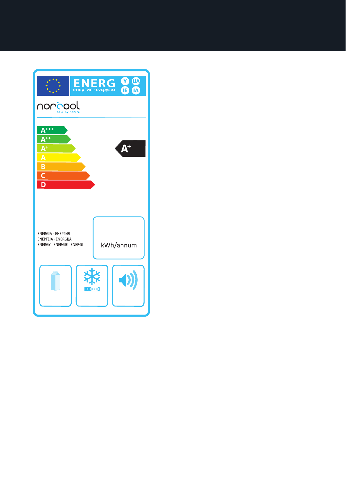
Energy labels
38 dB
0L
1L
1161 L
2010/1060
224
CORNER FRIDGE
cold by nature

4Content
1. Handling of waste .......................................................................................... 5
2. Safety rules and warnings........................................................................... 6
3. Product information...................................................................................... 8
4. Environment - energy conservation ....................................................... 9
5. Important information................................................................................ 10
6. Dimensions and technical specifications .............................................. 11
7. Pre-installation .............................................................................................. 14
8. Installation........................................................................................................ 15
8.1 Installing cabinet ........................................................................... 15
8.2. Installing full-cover stainless steel elements for free-
standing corner fridge cabinet ..................................................... 16
8.3. Integrating corner fridge.......................................................... 18
8.4. Installation of furniture fronts................................................ 18
8.5. Installation of furniture sides................................................. 19
8.6. Installation in floor to ceiling kitchen................................ 20
8.7. Preparing corner fridge........................................................... 20
9. Use and maintenance .................................................................................... 22
9.1 Noises ............................................................................................... 22
9.2 Cleaning and maintenance...................................................... 22
9.3 Troubleshooting and service .................................................. 22
10. Delivery terms and conditions ............................................................... 24
10.1 Consumer purchases................................................................ 24
10.2 Business purchase.................................................................... 26
11. Package list .................................................................................................... 27

5
1. Handling of waste
Waste management of the packaging:
The packaging protects the product against damage during transport. All packag-
ing may be recycled and is labelled for recycling. Make sure that all packaging is
discarded in a safe manner and is stored out of reach of children since irrespon-
sible use may be dangerous.
Ask the dealer or local authorities about where the packaging may be delivered
for recycling.
Waste management of the product:
This product falls under EU Directive 2012/19/EU concerning waste
from electrical and electronic equipment (WEEE). This symbol specifies
that the product must not be treated as household waste. Valuable raw
materials may be recovered by recycling used products. By ensuring
that the product is recycled correctly, you can contribute to preventing
potential negative consequences to the environment and human health.
When the product is to be discarded:
1. Pull out the mains plug.
2. Cut o the power cable.
3. Check that the cooling circuit is not damaged prior to waste management.
Information in the coolant is specified on the type plate.
4. Products that are no longer in use must be handled in a professional and cor-
rect manner in accordance with local statutes and regulations.

R600a
62. Safety rules and warnings
THE MANUFACTURER OF THE PRODUCT CANNOT BE HELD RESPONSIBLE FOR
DAMAGE THAT IS DUE TO THESE SAFETY RULES AND WARNINGS NOT BEING
FOLLOWED.
1. Read the use and installation instructions carefully before you start using the
product.
2. This product is intended for private use. The manufacturer cannot be held
responsible for damage in consequence of erroneous or unintended use of the
product.
3. Persons, who due to their mental or physical conditions, or due to their inexpe-
rience or lack of knowledge, are not in a condition to operate the cabinet in a
safe manner, must not use this cabinet without supervision or guidance from a
responsible person.
4. The product is not a toy! Due to the risk of injury, you must not let children
play with or in the vicinity of the product or play with the buttons. Have small
children under supervision while you are using the product. Older children may
only use the product if it has been explained to them how they can use it safely
and are familiar with the dangers of erroneous use.
5. Check that the product does not have any visible damage. Do not install or
use a damaged product. Contact the supplier immediately for further advice
before you install/connect up the power cord.
6. The product contains the coolant Isobutane (R600a), a natural gas that is envi-
ronmentally friendly. (R600a), that no parts of the cooling system have been
damaged during transport or installation. Leaking coolant can injure the eyes.
If the product has been damaged:
a. Avoid open flames and everything that can create sparks.
b. Disconnect the power cord.
c. Air out the room where the product is located, for several minutes.
d. Contact the supplier for further advice.
The more coolant a product contains, the larger the room it should be placed
in. Leaking coolant can form a flammable gas-air mixture in a room that is too
small. According to the EN378 standard, the room must have at least 1 m3 for
each 8 g of coolant. The quantity of coolant in the device is specified on the
type plate on the inside of the product.
7. Before you connect up the power cord, you must check that the information on
the type plate (voltage and connected load) accord with the power grid. This
information must match up in order to avoid risks of damage to the product.
Contact a qualified electrician if you have doubts.
8. Guarantees for the product’s electrical safety may only be given when there is
an uninterrupted connection between the product and an eective grounding
system that complies with the applicable local and national regulations. It is
extremely important that this fundamental safety requirement be fulfilled and

7
2. Safety rules and warnings
checked regularly. In the event of any doubts, the wiring network in the house
must be checked by a qualified electrician. The manufacturer cannot be held
responsible for product damage or personal injuries that are due to a deficient
or insucient grounding system, such as electrical shocks for example.
9. If the wiring is damaged or other repairs are necessary, then the work may
only be performed by an approved service technical such that the user is not
exposed to any dangers.
10.A guarantee is made only for the product being safe to use if it has been installed
and connected up in accordance with these use and installation instructions.
11. Installation, maintenance and repairs must only be performed by an authorised
repairman in accordance with national and local safety regulations. Repairs
and other work by unqualified personnel may be dangerous and the manufac-
turer will not be held responsible. The power cord must not be connected to
the power grid before maintenance or repairs have been performed.
12. The product is only completely disconnected from the power supply when:
a. the mains plug. has been pulled out
b. The fuse in the house installation is completely disconnected
c. The screw fuse has been removed (in countries where this is relevant)
13. Do not connect the product to the power grid with an extension cord. Exten-
sion cords do not provide satisfactory safety for the product (involve for exam-
ple a danger of overheating).
14.Do not store explosive substances or products that contain propellants (for
example aerosols) in the product. Thermostats that are activated can emit
sparks and pose a fire hazard. Flammable substances may explode.
15. Do not use electrical equipment in this product. Danger of sparks and explosion.
16. Do not use oil or grease on the door seal, because oil and grease can damage
the seal and gradually make it porous.
17.Do not block the valve openings, because it will make the product less eec-
tive, increase its power consumption and the product may be damaged.
18. The product is intended for use within definite climate classes (ambient tem-
perature) and ought not to be used outside such limits. The climate class is
specified on the type plate on the inside of the product and in chapter 6.
19. Do not use a steam cleaner to clean the product. Steam can penetrate between
the electronic components and cause shortcircuits.

8
The Norcool corner fridge is available in these models; for integration, for integra-
tion with stainless steel door and a freestanding model in all stainless steel.
They are designed for chilling food for use in private households. These User
instructions are general, and apply to all models.
The corner fridge units require a power supply of 220-240VAC 50 Hz and must be
connected to an earthed min. 10A mains socket. The mains socket must be easily
available. Corner fridge units have a capacity of 1161 liters and have 3m2 shelf area
without boxes. The maximum allowable load on door hinges (including furniture
front and goods) is 45kg. Weight of complete cold room door is 15kg. We recom-
mend that heavy products are not placed in the door. Use the shelves or floor.
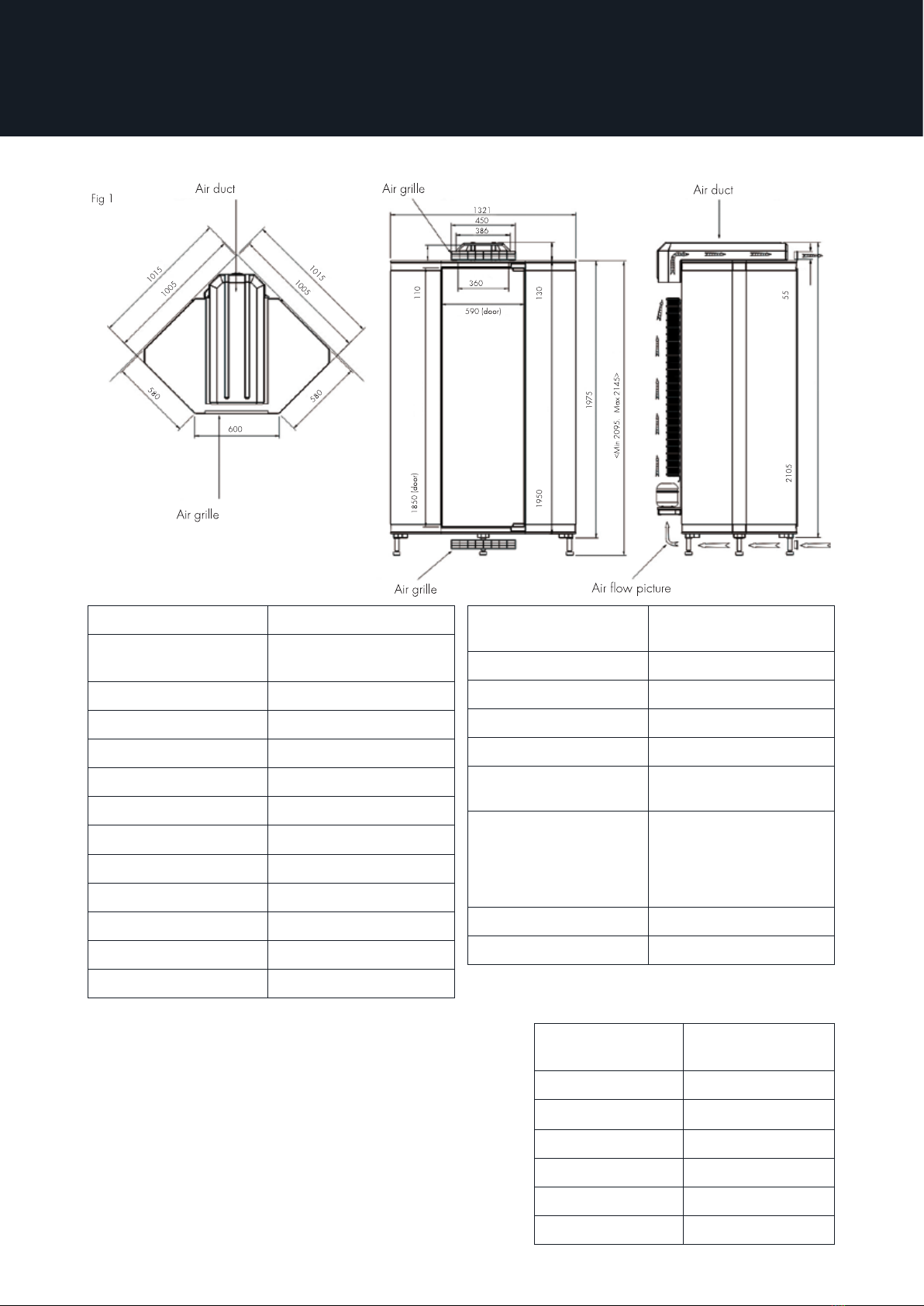
Always ensure there is sucient air circulation above and under the fridge (all
models). Freestanding corner fridges must have a gap of minimum 130mm from
top of the cabinet to the kitchen ceiling, and 25mm from bottom of the cabinet to
the kitchen floor. If the corner fridge is to be integrated in a floor to ceiling kitchen,
ensure sucient air circulation above and under the corner fridge by fitting an air
grille in the plinth and above the door, plus an air duct. See fig. 1. When integrat-
ing, air grilles must always be used. Select right- or left hinging of doors when
installing.
Room temperature where a corner fridge is installed must always be between 16
- 38° C.
A practical equipment pack is also oered to help you keep good order and orga-
nize the inside of the fridge. This consists of a wine shelf, bottle rack for 16 x 1.5
liter bottles and a practical basket for smaller dressing bottles.
3. Product information

9
4. Environment - energy conservation
4.1 Energy ecient use
The highest temperature will normally be in the uppermost door shelves since
they are located outside the air circulation. Here, butter will stay soft and cheese
will retain its aromatic taste. Because cold air sinks, it will normally be the coldest
at the bottom of the corner fridge. An evaporator fan is mounted on the refrig-
eration unit/ back wall, which circulates the cold air such that the temperature is
distributed in the fridge. The temperature will vary a few degrees between the top
and bottom, which is completely normal.
4.2 Measures for energy conservation
The most important energy conservation measure is avoid leaving the fridge
door open, this will cause increased running time and increased energy consump-
tion. Having good order and organization in your Corner Fridge cabinet will save
you much searching and time, and you will reduce the running time and energy
consumption.
Tips:
• Leftovers from hot food should be cooled to room temperature before they are
placed in the fridge.
• Defrost frozen goods in the fridge, since the food defrosts more gently and fro-
zen goods will emit cold to the fridge and save running time and energy.
• Avoid placing hot food in the fridge, since this increases frost formation and
increases running time.

10 5. Important information
To ensure proper installation and use and thereby prolong the lifetime of the prod-
uct, you must study this installation and user manual carefully prior to installa-
tion. Repairs must only be made by qualified personnel. The manufacturer will not
assume liability for any damage resulting from non-compliance with the following
instructions. Keep these instructions in a safe place as they contain many tips on
use and regular maintenance. The product will require maintenance even in nor-
mal use and replacement of parts which are worn out can be necessary. These
are not covered during the warranty period, but are covered by the guarantee in
accordance with the Sale of Goods Act.
Overvoltage protection is recommended to protect the fridge’s electronics. Elec-
trical safety for the appliance is only guaranteed if the earthing system in the
house has been mounted in a manner in accordance with the regulations.
A data plate with serial number is located on the inside back wall in the bottom
right corner. Serial number must always be stated when contacting service con-
tractor or manufacturer.
Scandinavian Appliances AS disclaims all liability for typographical errors in this
user manual and reserves the right to alter the product specifications.
11
6. Dimensions and technical specifications
Exterior dimensions 1015 mm x 1015 mm
External height
integrated
2095mm - 2145 mm (ad-
justable feet)
Freestanding height 1975 mm
Usable volume 1161 liters
Temperature range 1 - 12 °C
Volt/Hz 220-240 V AC 50 Hz
Climate class ST
Energy class A+
Energy consumption 223.8 kWh/year
Noise level 38 dB(A)
Thermostat setting Approx. 4 °C
Lightning 2 X LED 4 W
Defrosting Automatic
Insulation Polyurethane foam,
non-CFC
Coolant R600A
Door hinging Right or left
Weight Approx. 151 - 171 kg
Weight door Approx. 15 kg
Max. load door 30 kg incl. furniture pa-
nel and loading, in door
Shelves 5 hardened glass shel-
ves, max. load 15 kg
per shelf 4 pairs of wire
shelves and 1 pair of
wire baskets
Cable length 3.6 meters
Compressor Compressor cooling
Climate class Ambient/room
temperature
SN +10°C to +32°C
N +16°C to +32°C
ST +16°C to +38°C
T +16°C to +43°C
SN – ST +10°C to +38°C
SN – T +10°C to +43°C
Climate Classes
The product is intended for use within definite
climate classes (ambient temperature) and
ought not to be used outside such limits. The
climate classes are specified on the type plate
on the inside of the product. With respect to
the climate specifications, this product must
be used in climate class ST, which means an
ambient temperature of +16°C to +38°C.

12
Light:
When the door is opened, the light is switched on automatically. The light will be
switched o automatically when the door is closed.
Defrosting:
Defrosting occurs automatically.
Temperature settings and display functions:
How to adjust the temperature by using the controller buttons seen below.
Energy consumption reduction:
To reduce the energy consumption of the corner fridge over a period of time (e.g.
vacation), the temperature can be increased to 12˚C.
N.B.: The energy consumption reduction should only be used if none of the items
inside the corner fridge will be harmed by the reduced cooling eect.
Display icons & alarms
After connecting the corner fridge to the mains electricity, the fan
and compressor icon will blink for 3 minutes. Both icons are lit during
running time.
* Temperature range: 1 - 12˚C
6. Dimensions and technical specifications
NO. FUNCTION OPERATION
1ON/OFF
Arrow up
Press and hold the button for more than 3 seconds:
Turns corner fridge on/o.
2 Temperature setting* Hold the button until the temperature is blinking.
Adjust the temperature with arrow buttons (1 and 3).
Press the “set” button once to save.
3 Defrosting
Arrow down
Press and hold the button for more than 3 seconds:
Activates/deactivates manual defrosting. (Defrost icon
is lit during defrosting process.)
ICON FUNCTION OPERATION
COMPRESSOR ON/OFF
DEFROST ON/OFF
FAN ON/OFF
AUX OUTPUT ON/OFF

13
Display alarms:
Possible alarm codes are shown in the following table:
6. Dimensions and technical specifications
Alarm code Buzzer and alarm relay LED Alarm description Reset
E0 Active ON Probe 1 error = control Automatic
E1 Not Active ON Probe 2 error = defrost Automatic
E2 Not Active ON Probe 3 error = condenser/product Automatic
IA Active ON External alarm Automatic
dOr Active ON Open door alarm Automatic
LO Active ON Low temperature alarm Automatic
HI Active ON High temperature alarm Automatic
EE Not Active ON Unit parameter error Not possible
EF Not Active ON Operating parameter error Manual
Ed Not Active ON Defrost ended by timeout On first defrost
ended correctly
dF Not Active OFF Defrost running Automatic
cht Not Active ON Dirty condenser pre alarm Automatic
CHt Active ON Dirty condenser alarm Manual
EtC Not Active ON Clock alarm By setting the time
SrC (easy
split only)
Not Active ON Maintenance request signal Manual, set HMr=1

14 7. Pre-installation
Unpack the cabinet and check it for any transport damage. Do not use a dam-
aged product! In the event of damage, please contact the shipping company and
make sure that the damage is noted on the consignment note. Then check that all
the parts on the parts list at the back of this user guide are present. Contact your
vendor in the event of damage or deficiencies.
The corner fridge units require a power supply of 220-240VAC 50 Hz and must
be connected to an earthed min.10A mains socket. If the cord is not long enough
(3.6 m mains power cable is connected to the back wall.), then en electrician must
install a min. 10A socket closer to the fridge, e.g. on the ceiling above it. Never
allow the unit to be connected to an extension lead permanently. The socket must
be readily accessible for installation/service.
When fitting a new kitchen with a Norcool corner fridge, install the unit before the
rest of the kitchen on the site where it will stand permanently.
15
8. Installation
8.1 Installing cabinet
When installing the corner fridge, do NOT screw or drill anywhere else than shown
in the manual. If you do so it can ruin the construction and isolation ability.
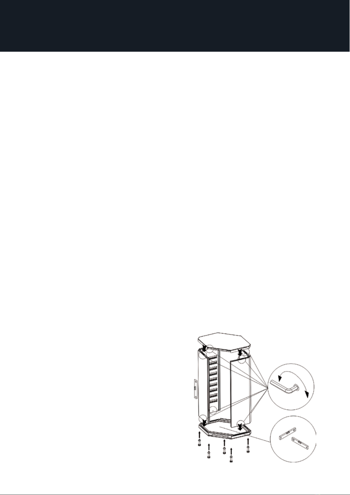
1. Floor element. Begin with the floor element. For integration into the kitchen,
install the adjustable feet to the floor element, and adjust to the desired height in
relation to plinth height of the kitchen. Check that the floor element is stable and
level. The maximum plinth height is190mm and the minimum is 145mm. Freestand-
ing corner fridges do not need adjustable feet. The floor element must be stable
and level. This is essential to ensure the other elements and door will achieve a
good seal.
2. Side walls. Before installing the side walls, check that the lock tabs engage the
lock housing. Twist the lock tabs back all the way until you hear a click. For cor-
rect locking, turn the Allen key approx. 145°. NOTE: The elements can creak when
being locked. Mount the side walls on the floor element and lock them together.
Fit the top element and lock into place. Fit the white plastic plugs supplied over
the lock holes to conceal them. NOTE: Power supply cable in back wall of ceiling
element must be accessible and hang down freely for connection of back wall.
There are mounted ledge lists for the door on all items. Check that the four fittings
are flush in the corners.
3. Roof element. It is important that there is minimum free space of 100mm from
top of the roof element to the ceiling due to disassembly if necessary. If fitting
full-cover stainless steel elements, then now go straight to “Installing full-cover
stainless steel elements for freestanding corner fridges.”
4. Back wall with refrigeration unit. The
mechanical element of the cooling wall must
face in towards the corner in the kitchen.
Before lifting the back wall through the door
opening in the fridge, use protective mate-
rial in the bottom floor to avoid scratches.
( Floor protection sheet in white plastic
material is also available as extra part num-
ber 9947551200) Assembly the backwall in
the niche by lifting the backwall through the
dooropening, tilt the top against you and lift
the backwall into the niche. Grasp the cord
from the ceiling element and connect this
cord to the back wall, labelled ”light”. Check
that the power cable could be reached after

16 8. Installation
installation! Screw back wall into place using the 5 white screws supplied with
plastic washers.
NOTE! Press back wall firmly whilst tightening screws.
Make sure that the electric cable is free.
8.2 Installing full-cover stainless steel elements for freestanding corner fridge
cabinet (see figure 3)
Stainless steel side plates
1. Preparation The corner fridge must be laid on its back with the door opening
upwards to fit the stainless steel elements on to the side walls. Lay a piece of card-
board or paper on the floor to prevent scratches. Make sure that the electric cable
from the top of the corner fridge is free, place a piece of cardboard in between the
top of the corner fridge and the floor.
NOTE: Do not remove the styrofoam from side plates!
2. Securing stainless steel side plates. Mount the stainless steel side plates onto
the side walls. Check elements are positioned correctly and secure with 8 (4,8mm
x 16mm) self-tapping screws supplied. Screw these into floor and ceiling in slots
on the stainless steel side plates using an electric screwdriver. Raise corner fridge
up for remaining installation. Go back to point 8.1 and continue with the rest of this
page. Stainless steel door panel (see figure 4)
1. Hinges. Unscrew the screws for the hinges, upper and lower (point 2 in fig. 4).
Then mount the hinges on the door. Remember the dierence between right and
left hinge!
2. Secure door panel. Lay door panel on a level surface, preferably cardboard, to
prevent scratches. Check that the handle side is not on same side as hinges. Posi-
tion the fridge door in middle of panel and screw into place with 6 of the screws

17
8. Installation
supplied in pre-drilled holes on upper and lower sides of the door. Insert plastic
plug in oblong hole in middle of hinge side to secure panel even better.
3. Handle Secure stainless steel handle using 3 screws supplied in pre-drilled holes
in door panel.
4. Cabinet door. Remove hinge retaining screws in floor and ceiling on side
selected for hinges using Allen key supplied. Open hinges fitted on fridge door.
Hold the door in the open position while inserting hinge screws through holes in
hinges. Finger tighten up to (not completely tightened) floor and ceiling. NOTE:
If working alone, place a support under fridge door at correct height for hinges.
Allow door to rest on this while installing hinges into place.
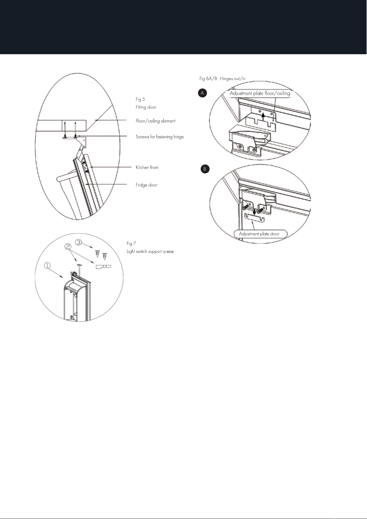
Light switch support piece (see Fig. 7) is mounted at the top of the door and
prepared for right-hinged door. If you want to change the door from right to left,
this plastic piece (2) must be moved to the opposite end of the door. Remove the
screws (3) and move the piece to the opposite end and fit the screw in the ready-
drilled holes.
5. The magnetic seal can be compressed after being packed and transported. It
will return to its original shape a while after being unpacked. Door can be adjusted
using adjustment plate supplied if the seal is compressed - see fig. 6B. If the mag-
netic seal is pressed too hard on door seal or is twisted; open door 90° and loosen
hinge screws to floor/ceiling, move adjustment plate inwards between hinge and
ceiling/floor and screw securely. See fig. 6A.
6. Adjustment and sealing. Door can be adjusted sideways to correct position and
then securely screwed. Examine whether the door can close properly. If you can
pull a sheet of paper out through the closed door without any great resistance,
then the door ought to be further adjusted.
18
8.3 Integration of corner fridge cabinet (see fig 9)
Adjust and level cabinet floor height in accordance with plinth height of your
kitchen. Depth of cover sides and/or worktop will determine distance from room
corners. Corner fridge may need to be pulled forward, as worktop should not be
deeper than cover side. This will avoid the door hitting the worktop. The ideal
combination is cover sides of 600mm and door plate 595mm. Pull corner 10mm
forward to reduce white line around door as much as possible.
NOTE: Avoid screwing kitchen front too tightly. 1 spacer block is supplied for
each side wall. Do not remove these, as they ensure air circulation and prevent
condensation on walls in the room.
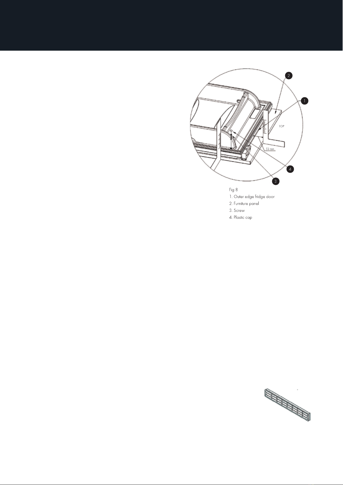
8.4 Fitting furniture fronts (see figures 5, 6 and 8)
1. Hinges. Remember dierence between right and left hinge. Remove screws in
countersunk holes on cold room door. Position correct hinge in recess and screw
securely.
8. Installation
19
2. Fitting furniture front. Drill holes from
the inside of the door through bushings
in external steel plate using Ø4 mm drill.
NOTE! Drilling and screwing must not be
done at places in the door other than in
through bushings since such may ruin the
design and insulating capability. Take into
account the furniture front thickness to
avoid screw through the furniture front.
Position furniture front(s) on a level surface.
Check up/down for fronts and handle posi-
tion. Position fridge door correctly on furni-
ture front(s). If in doubt about positioning,
fit fridge door to cabinet and check correct
positioning in relation to cornice seal and
side plates. To avoid over-tighten and dam-
aging plastic bushings or their hold in the
furniture front we recommend using hand
tools. Attach the furniture front by using the screws (4X45mm). The screw will
extend approximately 9mm into the furniture front. Press the supplied plastic caps
into the covers to conceal the screw heads.
3. Cabinet door. Remove hinge retaining screws in floor and ceiling on side selected
for hinges using Allen key supplied. Open hinges fitted on fridge door. Hold the
door in the open position while inserting hinge screws through holes in hinges.
Finger tighten up to (not completely tightened) floor and ceiling - see fig. 5.
NOTE: If working alone, place a support under fridge door at correct height for
hinges. Allow door to rest on this while screwing hinges into place.
4. Handle. The desired handle must be fastened vertically 25 mm from the outer
edge of the fridge door to the centre hole. The screw length depends on the han-
dle and thickness of the furniture panel (thickness of fridge door is 35 mm). Drill
the proper number of holes. Washers should be used for better fastening. Thread
washer on screw and fasten with handtool.
5. Air grilles. Cut an opening in plinth for air grille. The opening
must be 448 mm x 56 mm.
8.5 Fitting furniture sides (see figure 9)
1. Preparation. Corner fridge must be in place without shelves and other internal
fixtures in kitchen with door and front fitted.
8. Installation

20 8. Installation
Fitting furniture sides. Drill hole from the inside of the sidewalls through bushings
in external steel plate using Ø4 mm drill. NOTE! Drilling and screwing must not be
done at places in the sidewalls other than in through bushings since such may
ruin the design and insulating capability. Take into account the furniture sides
thickness to avoid screw through the furniture sides. Position furniture sides level
with upper edge of corner fridge and pull as far forwards towards furniture front
as possible to minimize gap between furniture front and furniture side. To avoid
over-tighten and damaging plastic bushings or their hold in the furniture sides
we recommend using hand tools. Attach the furniture sides by using the screws
(4X35mm). The screw will extend approximately 13mm into the furniture sides.
Press the supplied plastic caps into the covers to conceal the screw heads.
8.6 Installation in floor to ceiling kitchen
When installing a corner fridge in a floor to ceiling kitchen, an extra air grille and
air conduit must be fitted to ensure sucient air circulation above and below.
Place the air duct on the roof of the corner fridge. Integrate the corner fridge as
described in chapter 3. Cut a hole in the front panel of the door and the base for
mounting the air vent. Make sure the air vent is placed by the air duct outlet. When
installing the corner fridge in a kitchen that is 2.10 m, do not use the supplied air
vent and extra air duct outlet over the roof element.
8.7 Preparing corner fridge (for all models)
1. Preparation. Insert plastic plugs supplied into all open holes and bushings.
This manual suits for next models
2
Table of contents
Other Norcool Refrigerator manuals


