Nord Drivesystems B 1050 Series Product guide

B 1050 – en
Industrial gear units
Operating and Assembly Instructions

Industrial gear units – Operating and Assembly Instructions
2 B 1050 en-1819
Pos: 2/ A nl eit ung en /G et ri e be/ 0. Prol og /Sic her hei ts - un d Anwe nd ung s hi nw ei s e f ür Getri eb e [B105 0.. .B 2 05 0] @ 27 \mod_1550741709815_388.docx@ 2489430@ @ 1
General safety and operating instructions
1. General
Depending on its
protection class, the device may have live, bare,
moving or rotating parts or hot surfaces during operation,.
Unauthorised removal of covers, improper use, incorrect installation or
operation causes a risk of serious personal injury or material damage.
All transport, installation, commissioning and maintenance work must be
carried out by qualified specialist personnel (national accident
prevention regulations must be observed).
Within the meaning of this basic safety information, qualified specialist
person
nel are persons who are familiar with the installation, assembly,
commissioning and operation of the product and who have the training
and experience to recognise and avoid any hazards and risks.
2. Intended use
NORD products may only be used according to
the information in the
catalogue and the associated technical documentation.
Compliance
with the operating and installation instructions is a
prerequisite for fault-free operation
and for the fulfilment of any
warranty claims. These operating and installation instructions must
be read and understood before working with the device!
These operating and installation instructions contain important
information about servicing. They must therefore be kept
in close
proximity to the device.
All details regarding te
chnical data and permissible conditions at the
installation site must be complied with.
3. Transport, storage
Information regarding transport, storage and correct handling must be
complied with.
4. Installation
The device must be protected against impermissible loads. In particular,
during transport and handling, components must not be deformed or
changed.
Touching of electronic components and contacts must be
avoided.
5. Electrical connection
When working on live three-
phase motors, the applicable
national accident prevention regulations must be complied with
(e.g. BGV A3, formerly VBG 4).
The electrical installation must be implemented according to the
applicable regulations (e.g. cable cross-
section, fuses, earth
lead connections).
Information regarding EMC-compliant installation –
such as
shielding, earthing and installation of cables –
can be found in
the three-
phase motor documentation. Compliance with the limit
values specified in the EMC regulations is the responsibility of
the manufacturer of the system or machine.
6. Operation
Appropriate safety measures must be taken for applications
where failure of the device may result in injury.
Where necessary, systems in which NORD devices are installed
must be equipped with additional monitoring and protective
equipment according to the applicable safety requirements, e.g.
legislation concerning technical equipment, accident prevention
regulations, etc.
All covers and guards must be kept closed during operation.
7. Maintenance and repairs
After the de
vice has been disconnected from the power supply,
live equipment components and power connections should not
be touched immediately, because of possible charged
capacitors.
Further information can be found in this documentation.
These safety instructions must be kept in a safe place!
Documentation
B 1050 en-1819 3
Pos: 3/ A nl eit ung en /G et ri e be/ 0. Prol og /D o ku men tat i o n - Versionsliste[B 1050]@ 27\mod_1550672159365_388.docx@ 2489190 @ @ 1
Documentation
Designation:
B 1050
Material No.:
6052902
Series: Gear units and geared motors
Type series:
SK 5207 – SK 15507 and SK 5217 – SK 11217
Gear unit types: Industrial gear units
Version list
Title,
Date
Order number Remarks
B 1050,
January
2013
6052902 / 0213
-
B 1050,
September
2014
6052902 / 3814
General corrections
B 1050,
April 2015
6052902 / 1915
General corrections
B 1050,
March 2016
6052902 / 0916
General corrections
B 1050,
May 2017
6052902 / 1817
Revised
B 1050,
May 2019
6052902 / 1819
Extension of the series MAXXDRIVE®XT
General corrections
Table 1: Version list B 1050
Pos: 4/ Al lg emei n/ All ge mei ngül tig e M o dul e/---------Seitenumbruch kompakt---------@ 13\mod_1476369695906_0.docx@ 2265495@ @ 1

Industrial gear units – Operating and Assembly Instructions
4 B 1050 en-1819
Pos: 5/ Al lg e mei n/ All ge mei ng ülti ge Modul e/U r he ber rec ht s ver mer k @ 5\mod_1410955083459_388.docx@ 150427@ @ 1
Copyright notice
As an integral component of the device described here, this document must be provided to all
users in a suitable form.
Any editing or amendment or other utilisation of the document is prohibited.
Pos: 6/ Al lg emei n/ All ge mei ngül tig e M o dul e/H era usg eb er @ 0\mod_1325779078002_388.docx@ 5270@ @ 1
Publisher
Getriebebau NORD GmbH & Co. KG
Getriebebau-Nord-Straße 1 • 22941 Bargteheide, Germany • http://www.nord.com/
Fon +49 (0) 45 32 / 289-0 • Fax +49 (0) 45 32 / 289-2253
Member of the NORD DRIVESYSTEMS Group
===Endeder ListefürT extmarkeCopyright ===

Publisher
B 1050 en-1819 5

Industrial gear units – Operating and Assembly Instructions
6 B 1050 en-1819
Pos: 8/ A ll ge mei n/ S t euer mo d ule/ In h al ts ver zei c h nis @ 0 \mod_1317978518480_388.docx@ 4078@ @ 1
Table of Contents
=== Ende d er List e f ür Text m ar ke I nh al ts ver z ei ch ni s = ==
1Notes ..........................................................................................................................................................10
1.1 General information..........................................................................................................................10
1.2 Safety and information symbols .......................................................................................................10
1.3 Explanation of markings...................................................................................................................10
1.4 Intended use ....................................................................................................................................11
1.5 Safety information ............................................................................................................................12
1.6 Other documents..............................................................................................................................13
2Description of gear units ..........................................................................................................................14
2.1 Type designations and gear unit types.............................................................................................14
3Assembly instructions, storage, preparation, installation ....................................................................17
3.1 Transporting the gear unit................................................................................................................17
3.1.1 Standard gear units ............................................................................................................18
3.1.2 with motor adapter..............................................................................................................19
3.1.3 with V-belt drives ................................................................................................................20
3.1.4 with V-belt drive..................................................................................................................21
3.1.5 on motor swing base or base frame ...................................................................................22
3.2 Storage ............................................................................................................................................23
3.3 Long-term storage............................................................................................................................23
3.4 Inspecting the drive unit ...................................................................................................................24
3.5 Checking the type plate data............................................................................................................25
3.6 Checking the version........................................................................................................................26
3.7 Preparing for installation ..................................................................................................................27
3.8 Installing the gear unit......................................................................................................................29
3.9 Motor (Option: IEC, NEMA)..............................................................................................................31
3.10 Gear unit with hollow shaft (Option: A, EA)......................................................................................34
3.10.1 Hollow shaft with fastening element (Option: B) .................................................................35
3.10.2 Hollow shaft with shrink disc element (Option: S)...............................................................36
3.11 Flange version gear units (Option: F, FK, VL2/3/4/5, KL2/3/4).........................................................39
3.12 Motor base frame and motor swing base (Option: MS, MF).............................................................39
3.13 Motor mount (Option: MT)................................................................................................................40
3.14 Belt drives ........................................................................................................................................40
3.15 Internal cooling system (Option: CC) ...............................................................................................43
3.16 External cooling system (Option: CS1-X, CS2-X) ............................................................................44
3.17 Lubricant circulation (Option: LC, LCX)............................................................................................46
3.18 Torque supports (Option: D, ED, MS) ..............................................................................................47
3.19 Oil heater (Option: OH) ....................................................................................................................48
3.20 Brake................................................................................................................................................48
3.21 Covering cap (Option: H, H66, FAN, MF.., MS…)............................................................................48
3.22 Hubs on gear unit shafts ..................................................................................................................49
3.22.1 Drive coupling.....................................................................................................................51
3.22.1.1 Dog coupling 51
3.22.1.2 Turbo coupling 51
3.22.1.3 Dog coupling 52
3.22.2 Output coupling ..................................................................................................................53
3.23 Gear unit monitoring sensors ...........................................................................................................53
3.24 Subsequent paintwork......................................................................................................................53
4Commissioning .........................................................................................................................................54
4.1 Oil level and venting.........................................................................................................................54
4.2 Taconite seal....................................................................................................................................55
4.3 Lubricant circulation (Option: LC, LCX)............................................................................................56
4.4 Gear unit cooling with fan( Option: FAN)..........................................................................................57
4.5 Internal cooling system (Option: CC) ...............................................................................................58
4.6 External cooling system (Option: CS1-X, CS2-X) ............................................................................59
4.7 Oil heater (Option: OH) ....................................................................................................................60

Table of Contents
B 1050 en-1819 7
4.8 Temperature monitoring (Option: PT100) ........................................................................................60
4.9 Backstop / freewheeling coupling (Option: R, WX) ..........................................................................61
4.10 Checking the gear unit .....................................................................................................................65
4.11 Checklist ..........................................................................................................................................66
4.11.1 Obligatory ...........................................................................................................................66
4.11.2 Optional ..............................................................................................................................67
5Service and maintenance .........................................................................................................................68
5.1 Service and Maintenance Intervals ..................................................................................................68
5.2 Service and maintenance work ........................................................................................................70
5.2.1 Visual inspection.................................................................................................................71
5.2.2 Running noises...................................................................................................................71
5.2.3 Gear unit cooling with fan (Option: FAN)............................................................................71
5.2.4 Heat exchanger (Option CS2) ............................................................................................71
5.2.5 Shaft sealing rings..............................................................................................................72
5.2.6 Oil level...............................................................................................................................73
5.2.6.1 Oil level screw 73
5.2.6.2 Oil inspection glass/oil level glass (Option: OSG), Oil level indicator (Option: OST) 74
5.2.6.3 Oil dipstick (Option: PS) 74
5.2.6.4 Oil level tanks (Option: OT) 74
5.2.7 Venting ...............................................................................................................................75
5.2.7.1 Vent filter (Option: FV) 75
5.2.7.2Cellulose filter (Option: EF) 75
5.2.7.3 Drying agent filter (Option: DB) 76
5.2.8 Rubber buffer (Option: ED).................................................................................................76
5.2.9 Piping .................................................................................................................................76
5.2.9.1 Piping (Option: LC, LCX, OT) 76
5.2.9.2 Hose lines (Option: LC, LCX, CS1, CS2, OT) 76
5.2.10 Oil filter (Option: CS1-X, CS2-X, LC/LCX) ..........................................................................77
5.2.11 Bearings is the output flange (Option: VL2/3/4/6, KL2/3/4/6)..............................................77
5.2.12 Taconite seal ......................................................................................................................78
5.2.13 Changing the oil..................................................................................................................79
5.2.14 Internal cooling system (Option: CC)..................................................................................80
5.2.15 Bearings in the gear unit.....................................................................................................80
5.2.16 V-belts (belt drives).............................................................................................................81
5.2.17 General overhaul................................................................................................................81
6Disposal .....................................................................................................................................................82
7Appendix....................................................................................................................................................83
7.1 Standard positions of the oil drain, vent and oil level .......................................................................83
7.2 Installation orientation ......................................................................................................................97
7.2.1 Helical gear unit..................................................................................................................97
7.2.2 Bevel helical gear unit ........................................................................................................97
7.3 Lubricants ........................................................................................................................................98
7.3.1 Roller bearing greases .......................................................................................................98
7.3.2 Types of lubricant oil...........................................................................................................99
7.3.3 Lubricant quantities ..........................................................................................................101
7.3.3.1 Helical gear units 101
7.3.3.2 Helical bevel gear units 102
7.3.3.3 MAXXDRIVE®XT industrial helical bevel gear unit 102
7.4 Torque values ................................................................................................................................103
7.5 Tolerances for bolting surfaces ......................................................................................................103
7.6 Troubleshooting .............................................................................................................................104
7.7 Leakage and leak-tightness ...........................................................................................................106
7.8 Repair information..........................................................................................................................108
7.8.1 Repairs .............................................................................................................................108
7.8.2 Internet information...........................................................................................................108
7.9 Abbreviations .................................................................................................................................109

Industrial gear units – Operating and Assembly Instructions
8 B 1050 en-1819
Pos: 10 /Al lg e mei n/ Ste u erm o dul e/ Abbi ld ung s ver z eich nis @ 0\mod_1317978515699_388.docx@ 3917 @ @ 1
List of illustrations
=== Ende d er List e f ür Text m ar ke A b bi ldu ng s ver zei c h ni s == =
Figure 1: MAXXDRIVE®XT 2-stage helical bevel gear unit .................................................................................. 16
Figure 2: Transport of standard gear unit .............................................................................................................. 18
Figure 3: Transport of gear unit with motor adapter............................................................................................... 19
Figure 4: Transport of agitator version gear unit.................................................................................................... 20
Figure 5: Transport of agitator version gear units.................................................................................................. 21
Figure 6: Transport of gear unit with motor swing base or base frame.................................................................. 22
Figure 7: Name plate (example) ............................................................................................................................ 25
Figure 8: Centre of gravity of motor....................................................................................................................... 32
Figure 9: Fitting the coupling to the motor shaft..................................................................................................... 33
Figure 10: Applying lubricant to the shaft and the hub........................................................................................... 34
Figure 11: Assembly and disassembly of the fastening element (schematic diagram).......................................... 35
Figure 12: Machine shaft assembly for special hollow shafts with shrink discs ..................................................... 37
Figure 13: Fitted shrink disc................................................................................................................................... 38
Figure 14: V-belt pulley (disassembled/assembled) .............................................................................................. 42
Figure 15: Axle alignment (belt drives) .................................................................................................................. 42
Figure 16: Cooling cover with cooling coil fitted (schematic diagram) ................................................................... 43
Figure 17: Industrial gear unit with CS1-X and CS2-X cooling systems ................................................................ 44
Figure 18: Hydraulic plan of industrial gear units with CS1-X and CS2-X cooling systems ................................... 45
Figure 19: Permissible installation tolerances of the torque support (Option D and ED) (schematic diagram)...... 47
Figure 20: Correct assembly of drive elements ..................................................................................................... 49
Figure 21: Example of a simple pulling device....................................................................................................... 50
Figure 22: Switching pin with separate mechanical switch.................................................................................... 52
Figure 23: Activation of the pressure vent ............................................................................................................. 55
Figure 24: Testing a Taconite seal ........................................................................................................................ 55
Figure 25: Industrial gear unit with backstop (schematic diagram)........................................................................ 61
Figure 26: MSS7 seal ............................................................................................................................................ 72
Figure 27: Checking the oil level with a dipstick .................................................................................................... 73
Figure 28: Checking the oil level with an oil dip-stick............................................................................................. 74
Figure 29: Vent filter (Option FV)........................................................................................................................... 75
Figure 30: Cellulose filter (Option EF) ................................................................................................................... 75
Figure 31: Re-greasing Taconite seals.................................................................................................................. 78
Figure 32: Numbering of oil screw holes on SK 5207 – SK 10507 ........................................................................ 90
Figure 33: Numbering of oil screw holes on SK 11207 – SK 15507 ...................................................................... 96
Figure 34: Helical gear unit installation positions with standard mounting surface................................................ 97
Figure 35: Bevel gear unit installation positions with standard mounting surface.................................................. 97

List of tables
B 1050 en-1819 9
Pos: 12 /Al lg e mei n/ Ste u erm o dul e/T ab ell en ver zei c hni s @ 0\mod_1317978519199_388.docx@ 4124@ @ 1
List of tables
=== Ende d er List e f ür Text m ar ke T a bel l en verz eic hnis == =
Table 1: Version list B 1050..................................................................................................................................... 3
Table 2: Type designations and gear unit types .................................................................................................... 14
Table 3: Versions and options ............................................................................................................................... 15
Table 4: Explanation of type plate ......................................................................................................................... 26
Table 5: IEC and NEMA motor weights ................................................................................................................. 31
Table 2: Transnorm motor weights........................................................................................................................ 32
Table 6: Oil spaces as delivered............................................................................................................................ 54
Table 7: Backstop lift-off speeds SK 5..07 – SK 10..07 ......................................................................................... 62
Table 8: Backstop lift-off speeds SK 11..07 – SK 15..07 ....................................................................................... 63
Table 9: Backstop lift-off speeds SK 5..17 – SK 11..17 ......................................................................................... 64
Table 10: Obligatory checklist for commissioning.................................................................................................. 66
Table 11: Optional checklist for commissioning..................................................................................................... 67
Table 12: Service and Maintenance Intervals........................................................................................................ 69
Table 13: Disposal of materials ............................................................................................................................. 82
Table 14: Position of housing options on oil screw holes (standard installation positions) .................................... 84
Table 15: Roller bearing greases........................................................................................................................... 98
Table 16: Lubricant oil table................................................................................................................................. 100
Table 17: Lubricant quantities for helical gear units............................................................................................. 101
Table 18: Lubricant quantities for bevel helical gear units ................................................................................... 102
Table 19: Lubricant quantities MAXXDRIVE®XT bevel gear unit........................................................................ 102
Table 20: Torque values...................................................................................................................................... 103
Table 22: Overview of malfunctions..................................................................................................................... 105
Table 23: Definition of leakage according to DIN 3761........................................................................................ 107
Pos: 15 /A nl ei tu nge n/ Ge tri ebe /1. Hin wei s e/ 1. H i n weis e @ 3\mod_1368690405560_388.docx @ 65212@ 1@ 1
Industrial gear units – Operating and Assembly Instructions
10 B 1050 en-1819
1 Notes
Pos:16/Anleitungen/Getriebe/1.Hinweise/AllgemeineHinweise@ 27\mod_1550742220897_388.docx@ 2489 466 @ 2 @ 1
1.1 General information
Read the Operating Manual carefully prior to performing any work on or putting the gear unit into
operation. Strict compliance with the instructions in this operating manual is essential. This Operating
Manual and all associated special documentation must be kept in the immediate vicinity of the gear
unit.
Getriebebau NORD accepts no liability for personal injuries or damage to material or assets which
result from failure to observe the operating instructions, incorrect operation, deployment of
inadequately qualified personnel, improper use or modifications to the gear unit, including installed or
attached components.
General wearing parts, e.g. radial seals are excluded from the warranty.
If additional components are attached to or installed on or in the gear unit (e.g. motor, cooling system,
pressure sensor etc.) or components (e.g. cooling system) are supplied with the order, the operating
instructions for these components must be observed.
If geared motors are used, compliance with the Motor Operating Manual is also necessary.
If you do not understand the contents of this Operating Manual or additional operating instructions,
please consult Getriebebau NORD!
Pos: 17 /A nl ei tu nge n/ Ge tri ebe /1. Hin wei s e/Si c her hei ts- un d H i n wei sz eic h en [_Ti t el] @ 3\mod_1370591783249_388.docx@ 76351@ 2 @ 1
1.2 Safety and information symbols
Pos: 18 /A nl ei tu nge n/ El e ktr o ni k/FU und Star t er/ 1. Allg e mei n es/ Si ch er hei ts- u nd Inst allati onshi nweis e und War n- Gef ahr en hi nw eis e/ Er lä uter u ng d er ver we nd et e n A usz ei c hnu ng e n @ 22\mod_1530603439595_388.docx@ 2429680@ 2 @ 1
1.3 Explanation of markings
DANGER
Indicates an immediate danger, which may result in death or very serious injury if it is not avoided.
WARNING
Indicates a dangerous situation, which may result in death or serious injury if it is not avoided.
CAUTION
Indicates a dangerous situation, which may result in minor injuries if it is not avoided.
NOTICE
Indicates a situation, which may result in damage to the product or its environment if it is not avoided.
Information
Indicates hints for use and especially important information to ensure reliability of operation.
Pos: 19 /Allgemein/AllgemeingültigeM odul e/ ---------Seite num br uc h ko m pak t --------- @ 13 \mod_1476369695906_0.docx@ 2265495@ @ 1

1 Notes
B 1050 en-1819 11
Pos: 20 / A nl ei tu ng e n/ Ge tr ie be /1. Hin w eis e/B es ti m mu ng s ge mäß e V er w e nd ung [B1 05 0] @ 17 \mod_1492069354889_388.docx@ 2340259@ 2@ 1
1.4 Intended use
These gear units generate a rotational movement and are intended for use in commercial systems.
The gear unit must only be used according to the information in the technical documentation from
Getriebebau NORD.
Commissioning (start of proper operation) is prohibited until it has been established that the machine
complies with the local laws and directives. The EMC Directive 2004/108/EC and the Machinery
Directive 2006/42/EC in their currently valid scope of application must be complied with in particular.
DANGER Explosion hazard
Serious injury and material damage due to explosion are possible.
• Use in explosion hazard areas is prohibited.
WARNING Injury to persons
Appropriate safety measures must be taken in the case of applications in which failure of a gear unit or geared
motor may cause a hazard to persons.
• Safeguard a wide area around the hazard zone.
WARNING
Material damage and personal injury
If the gear unit is not used as designed, this may cause damage to the gear unit or the premature failure of
components. Personal injury as a result of this cannot be ruled out.
• Strict compliance with the technical data on the type plate is essential. The documentation must be observed.
Pos: 21 /Al lg emei n/Al lg em eing ülti ge M od ule/ ---------Seite num bruc h kom pak t --------- @ 13 \mod_1476369695906_0.docx@ 2265495@ @ 1

Industrial gear units – Operating and Assembly Instructions
12 B 1050 en-1819
Pos: 22 /A nl ei tu nge n/ Ge tri ebe /1. Hin wei s e/Si c her hei ts hi nw eis e [ B1 050 ] @ 3\mod_1368692826860_388.docx@ 65841@ 2 @ 1
1.5 Safety information
Observe all safety information, including that provided in the individual sections of this Operating
Manual. All national and other regulations on safety and accident prevention must also be observed.
DANGER Severe personal injury
Serious physical and property damage may result from inappropriate installation, non-designated use, incorrect
operation, non-compliance with safety information, unauthorised removal of housing components or safety covers
and structural modifications to the gear unit.
Work, e.g. transportation, storage, installation, electrical connection, commissioning, servicing, maintenance and
repair must only be performed by qualified specialist personnel
• Observe the Operating Manual
• Observe the safety information
• Observe the safety and accident prevention regulations
• Tighten the driven elements or secure the parallel keys before switching on
• Do not make any structural modifications
• Do not remove any safety devices
• If necessary, wear hearing protection when working in the immediate vicinity of the gear unit
• All rotating components must be provided with guards. As standard, covers are fitted by NORD. The covers
must always be used if contact protection is not provided by other methods.
DANGER Injury to persons
The surfaces of gear units or geared motors may become hot during or shortly after operation. Danger of burns!
• Installation and maintenance work must only be performed when gear unit is at a standstill and has cooled
down. The drive must be isolated and secured to prevent accidental start-up.
• Wear protective gloves.
• Shield hot surfaces with contact guards.
• Do not store inflammable objects or substances in the immediate vicinity of the gear unit.
WARNING
Injury to persons
Serious injury and material damage due to improper transport are possible.
• No additional loads may be attached.
• Transportation aids and lifting gear must have an adequate load-bearing capacity.
• Pipes and hoses must be protected from damage.

1 Notes
B 1050 en-1819 13
CAUTION Injury to persons
Danger of cuts from exterior edges of attachment adapters, flanges and covers.
Contact freezing with metallic components in case of low temperatures.
• In addition to personal protective equipment, wear suitable protective gloves and suitable goggles during
assembly, commissioning, inspection and maintenance, in order to prevent injuries.
It is recommended that repairs to NORD products are carried out by the NORD Service department.
Pos: 23 /A nl ei tu nge n/ Ge tr i ebe /1. Hin w eis e/ Wei ter e U nt er lag e n @ 3\mod_1368693112418_388.docx@ 65889@ 2 @ 1
1.6 Other documents
Further information may be obtained from the following documents:
• Gear unit catalogues (G1000, G1012, G1014, G1035, G1050, G2000),
• Operating and maintenance instructions for the electric motor,
• if applicable, the Operating Manuals for attached or supplied options
Pos: 25 /A nl ei tu nge n/ Ge tr i ebe /2. Getr i eb eb esc hrei b ung / 2. Getri e be bes c hr eib u ng [ Ti t el] @ 3\mod_1368691027023_388.docx@ 65591@ 1 @ 1
Industrial gear units – Operating and Assembly Instructions
14 B 1050 en-1819
2 Description of gear units
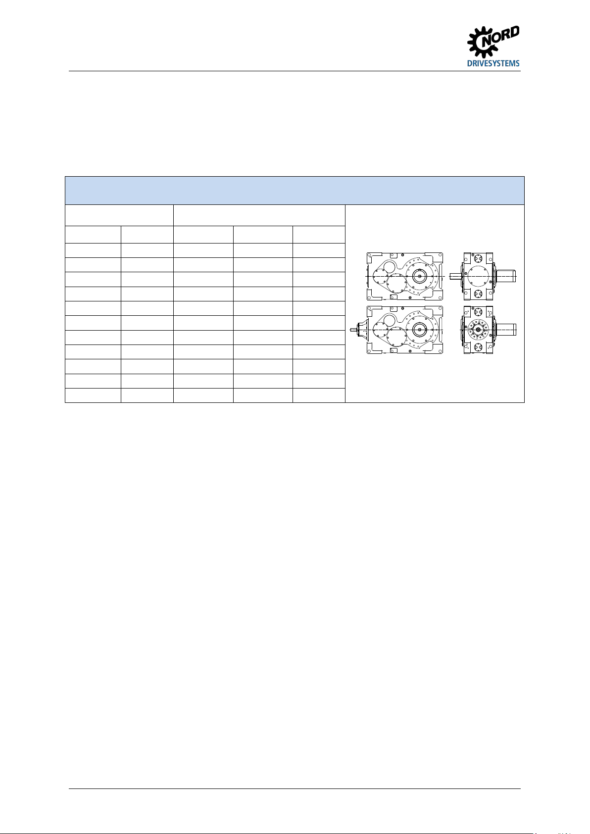
Pos: 26 /A nlei tunge n/Ge triebe /2. Getr ieb ebeschr eib ung/T ypenb ezeic hnung en und Ge trie beart en_01 [B 1050, B 2050] @ 29 \mod_1551802372814_388.docx@ 2498172@ 2 @ 1
2.1 Type designations and gear unit types
Gear unit types / Type designations
Helical gear units
Helical bevel gear units
2-stage 3-stage 2-stage 3-stage 4-stage
SK 5207 SK 5307 SK 5217 SK 5407 SK 5507
SK 6207
SK 6307
SK 6217
SK 6407
SK 6507
SK 7207
SK 7307
SK 7217
SK 7407
SK 7507
SK 8207
SK 8307
SK 8217
SK 8407
SK 8507
SK 9207
SK 9307
SK 9217
SK 9407
SK 9507
SK 10207
SK 10307
SK 10217
SK 10407
SK 10507
SK 11207 SK 11307 SK 11217 SK 11407 SK 11507
SK 12207
SK 12307
SK 12407
SK 12507
SK 13207
SK 13307
SK 13407
SK 13507
SK 14207 SK 14307
SK 14407 SK 14507
SK 15207
SK 15307
SK 15407
SK 15507
Table 2: Type designations and gear unit types
Double gear units consist of two single gear units.
SK 5207 - SK 15507 and SK 5217 – SK 11217 gear units should be treated according to these
instructions. The operating and assembly manual B 1000 should be used for attached gear units.
Type designation for double gear units: e. g. SK 13307 /7282 (consisting of single gear units
SK 13307 and SK 7282).
Pos: 27 /All ge mei n/Al lge mei ng ültig e M odul e/---------Sei te num bruc h kom pak t --------- @ 13 \mod_1476369695906_0.docx@ 2265495@ @ 1

2 Description of gear units
B 1050 en-1819 15
Pos: 28 /A nl ei tu nge n/ Ge tri ebe /2. Getr ie b ebes c hrei b ung /T yp en bez eic h nu nge n undGetriebearten_02[B1050]@ 30\mod_1552914025076_388.docx@ 2510772@ @ 1
Versions / Options
Abbreviation
Description
Details on type plate
See Section 3
See Section 4
Abbreviation
Description
Details on type plate
See Section 3
See Section 4
A
Hollow shaft version
X
X
…K
with elastic coupling
X
B
Fastening element
X
X
…T
with hydrodynamic coupling
X
CC
Cooling coil
X
X
X
MS…
Motor swing base
X
X
CS1-X
Cooling system oil / water
X
X
X
…B
with brake
X
CS2-X
Cooling system oil / air
X
X
X
…K
with elastic coupling
X
D
Torque support
X
X
…T
with hydrodynamic coupling
X
EA
Splined hollow output shaft
X
X
MT
Motor mount
X
X
ED2) Elastic torque support X NEMA
Standard NEMA motor
attachment
X
EV
Splined solid output shaft
X
OH
Oil heater
X X
EW
Splined drive shaft
OT
Oil level tank
X
F
Block flange
X
X
PT100
Temperature sensor
X
FAN
Fan
X
R
Backstop
X
X
FK
Collar flange
X
S
Shrink disc
X
X
F1
Drive flange
X
V
Solid output shaft
X
H/H66
Covering cap as contact guard
X
X
VL
Reinforced bearings
X
IEC Standard IEC motor mounting X VL2
Agitator version
- Reinforced bearings
X X
KL2 Agitator version
- Standard bearings X X VL3
Agitator version
- Reinforced bearings
- Drywell
X X
KL3
Agitator version
- Standard bearings
- Drywell
X X VL4
Agitator version
- Reinforced bearings
- True Drywell
X X
KL4
Agitator version
- Standard bearings
- True Drywell
X X VL6
Agitator version
- Reinforced bearings
- True Drywell
- Foot mounting
X X
KL6
Agitator version
- Standard bearings
- True Drywell
- Foot mounting
X X X VL5 Extruder flange version X X
L
Solid output shaft on both sides
X
W
One free drive shaft journal
LC(X)1
)
Lubricant circulation X X X W2 Two free drive shaft journals
MC
Motor bracket
X
W3
Three free drive shaft journals
MF...
Motor base frame
X
X
WX
Auxiliary drive unit
X
…B
with brake
X
1)
with pressure switch
2)
Also only stated with D on the type plate
Table 3: Versions and options
Pos: 29 /All ge mei n/Al lge mei ng ültig e M odul e/---------Sei te num bruc h kom pak t --------- @ 13 \mod_1476369695906_0.docx@ 2265495@ @ 1

Industrial gear units – Operating and Assembly Instructions
16 B 1050 en-1819
Pos: 30 /A nleitu ngen/ Getri ebe/2. G etrie bebesc hrei bung/ Typ enbezei chnu ngen un d Getri ebear ten_ 03 [B105 0, B20 50] @ 30\mod_1552914035630_388.docx@ 2510809@ @ 1
Certain versions / options can only be used for particular gear unit sizes or configurations.
Figure 1: MAXXDRIVE®XT 2-stage helical bevel gear unit
Pos: 32 /A nleitu ngen/ Getri ebe/3. M ontag e, Lager ung, Vor berei tung, Au fstel lung/3 .M ontag eanl eitung, L ager ung, Vor bereit ung, Aufstellung@ 23\mod_1531915085387_388.docx@ 2434207@ 1 @ 1

3 Assembly instructions, storage, preparation, installation
B 1050 en-1819 17
3 Assembly instructions, storage, preparation, installation
Please note all safety information 1.5 "Safety information"and warning information in the relevant
sections.
Pos: 33 /A nleitu ngen/ Getri ebe/3. M ontag e, Lager ung, Vor berei tung, Au fstel lung/T rans port des Ge trie bes -Allgemein[B1050_B2050]@ 17\mod_1492760671058_388.docx@ 2341179@ 2@ 1
3.1 Transporting the gear unit
WARNING Hazard due to heavy loads
Severe injuries and material damage due to falling, swinging or tipping heavy loads are possible.
• To prevent injury, the danger area must be generously cordoned off.
• Standing under the gear unit during transport is extremely dangerous.
• Use adequately dimensioned and suitable means of transportation. Lifting tackle must be designed for the
weight of the gear unit. The weight of the gear unit can be obtained from the dispatch documents.
• If geared motors have an additional eyebolt attached to the motor, this must not be used.
• Only the four ring bolts provided may be used for transporting the gear unit.
CAUTION
Slipping hazard
Transport damage to the gear unit or gear unit components may result from the leakage of lubricants. There is a
slipping hazard due to leaked lubricants.
• The drive unit must be inspected and may only be installed if no transportation damage or leaks are visible. In
particular the radial seals and the sealing caps must be inspected for damage.
NOTICE Gear unit damage
Damage to the gear unit due to improper use is possible.
• Prevent damage to the gear unit. Impacts to the free ends of the shafts may cause internal damage to the
gear unit.
• The ends of the shafts must not be used for transportation, as this may seriously damage the gear unit.
An additional lashing point may be required for versions which deviate greatly from the following
illustrations, or in the case of additional drive units and components.
In this case, please contact NORD Service.
Pos: 34 /All ge mei n/Al lge mei ng ültig e M odul e/---------Sei te num bruc h kom pak t --------- @ 13 \mod_1476369695906_0. docx@ 2265495@ @ 1

Industrial gear units – Operating and Assembly Instructions
18 B 1050 en-1819
Pos: 35 /A nleit ungen/ Getr iebe/3. M ontag e, Lager ung, V orberei tung , Aufstel lung /Trans port des Ge trie bes -Standardgetriebe[B1050_B2050]@ 28\mod_1551451615952_388. docx@ 2494466 @ 3@ 1
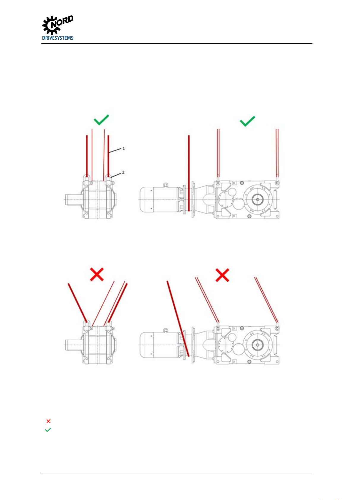
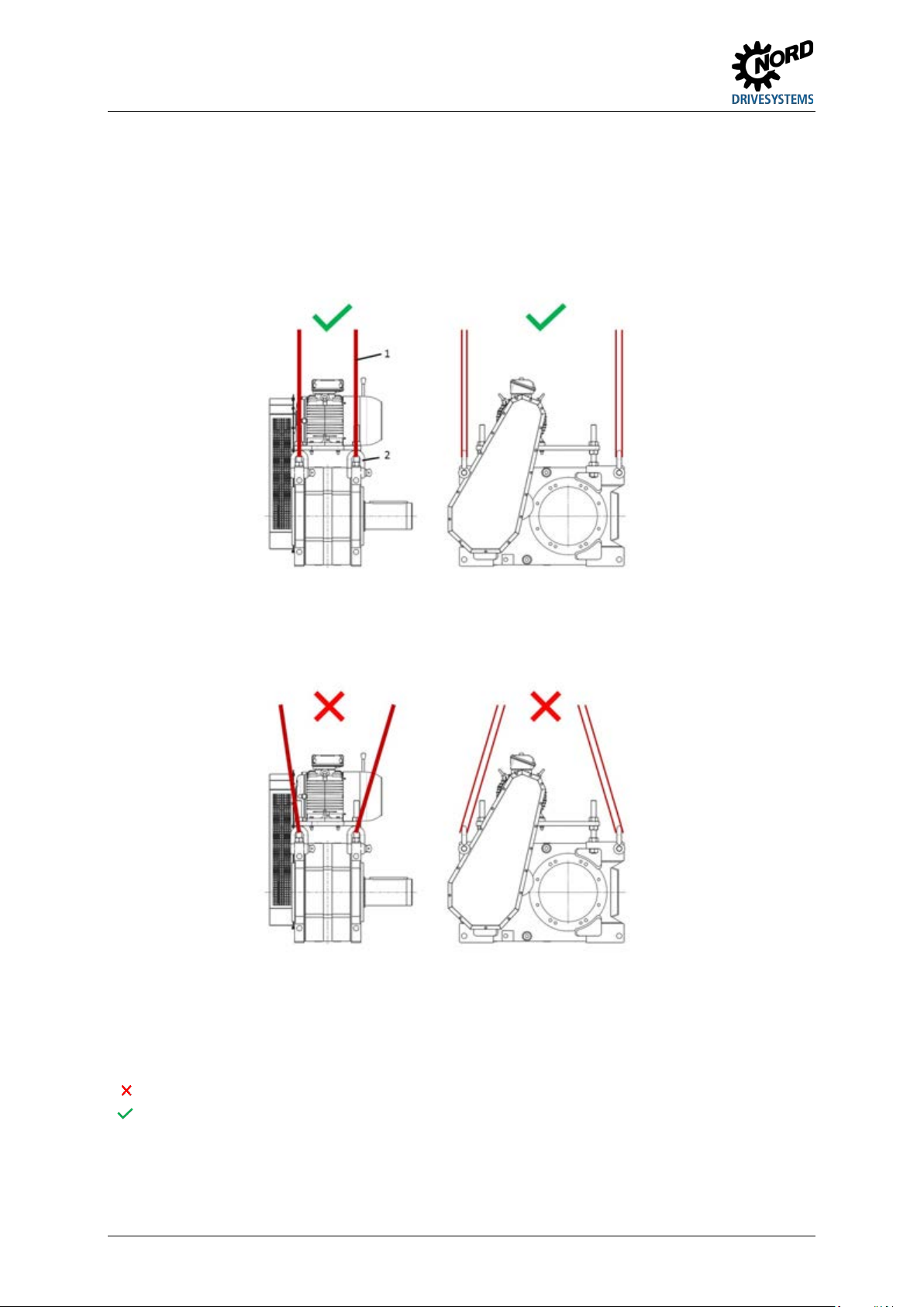
3.1.1 Standard gear units
Gear units may only be transported with lifting ropes and chains or lifting straps at an angle of 90° to
70° to the horizontal.
Legend
1:
Lifting strap
2:
Shackle
:
Not permissible
:
Permissible
Figure 2: Transport of standard gear unit
Pos: 36 /All ge mei n/Al lge mei ng ültig e M odul e/---------Sei te num bruc h kom pak t --------- @ 13 \mod_1476369695906_0.docx@ 2265495@ @ 1
3 Assembly instructions, storage, preparation, installation
B 1050 en-1819 19
Pos: 37 /A nleitu ngen/ Getri ebe/3. M ontag e, Lager ung, Vor berei tung, Au fstel lung/T rans port des Ge trie bes -Motoradapter[B1050_B2050]@ 29\mod_1552033260962_388.docx@ 2499916@ 3@ 1
3.1.2 with motor adapter
Gear units with motor adapters may only be transported with lifting ropes and chains or lifting straps at
an angle of 90° to 70° to the horizontal.
The ring bolts on the motor must not be used for transportation.
Legend
1:
Lifting strap
2:
Shackle
:
Not permissible
:
Permissible
Figure 3: Transport of gear unit with motor adapter
Pos: 38 /All ge mei n/Al lge mei ng ültig e M odul e/---------Sei te num bruc h kom pak t --------- @ 13 \mod_1476369695906_0. docx@ 2265495@ @ 1
Industrial gear units – Operating and Assembly Instructions
20 B 1050 en-1819
Pos: 39 /A nleit ungen/ Getr iebe/3. M ontag e, Lager ung, V orberei tung , Aufstel lung /Trans port des Ge trie bes -Keilriemenantrieb[B1050] @ 27\mod_1551104882121_388. docx@ 2490614@ 3@ 1
3.1.3 with V-belt drives
Gear units with V-belt drives may only be transported with lifting ropes and chains or lifting straps at
an angle of 90° to 70° to the horizontal.
The ring bolts on the motor and the motor bracket must not be used for transportation.
Legend
1:
Lifting strap
2:
Shackle
:
Not permissible
: Permissible
Figure 4: Transport of agitator version gear unit
Pos: 40 /All ge mei n/Al lge mei ng ültig e M odul e/---------Sei te num bruc h kom pak t --------- @ 13 \mod_1476369695906_0. docx@ 2265495@ @ 1
This manual suits for next models
51
Table of contents
Other Nord Drivesystems Engine manuals


