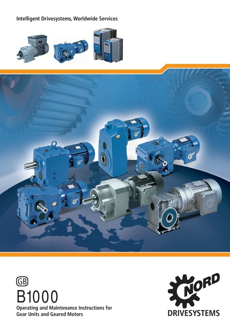
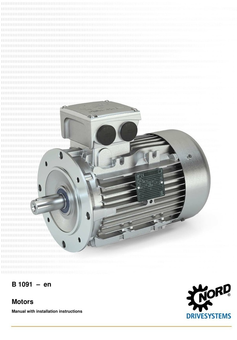
Nord Drivesystems PMSM Specification sheet

B 5000 – en
Synchronous motors (PMSM)
Manual with installation instructions

Synchronous motors (PMSM) – Manual with installation instructions
2 B 5000 en-2621
Read this manual
This manual contains the installation manual and other information for safe motor use.
Read this manual carefully prior to performing any work on or operating the motor. Always observe the
instructions in this manual.
Keep this manual in the vicinity of the motor so that it is available if required.
Please also note the following documents:
• Catalogue IE4/IE5 synchronous motors (TI60_0001),
• Product documentation for equipment which is attached or provided.
Please contact Getriebebau NORD GmbH & Co. KG if you require further information.

Documentation
B 5000 en-2621 3
Documentation
Title:
B 5000
Order number:
6055002
Series:
Three-phase synchronous motors
SK 56… to SK 132…
Version list
Title,
Date
Order number Remarks
B 5000
,
June 2021
6055002
/ 2621 -
Table 1: Version list B 5000

Synchronous motors (PMSM) – Manual with installation instructions
4 B 5000 en-2621
Copyright notice
As an integral component of the device described here, this document must be provided to all
users in a suitable form.
Any editing or amendment or other utilisation of the document is prohibited.
Publisher
Getriebebau NORD GmbH & Co. KG
Getriebebau-Nord-Straße 1 •22941 Bargteheide, Germany •http://www.nord.com
Fon +49 (0) 45 32 / 289-0 •Fax +49 (0) 45 32 / 289-2253
Member of the NORD DRIVESYSTEMS Group

Publisher
B 5000 en-2621 5

Synchronous motors (PMSM) – Manual with installation instructions
6 B 5000 en-2621
Table of Contents
1Safety information.....................................................................................................................................10
1.1 Intended use ....................................................................................................................................10
1.2 Do not make any modifications. .......................................................................................................10
1.3 Only use in perfect condition............................................................................................................10
1.4 Performing inspection and maintenance work .................................................................................10
1.5 Personnel qualification.....................................................................................................................11
1.6 Safety for particular activities ...........................................................................................................11
1.6.1 Check for transport damage ...............................................................................................11
1.6.2 Hazards when lifting ...........................................................................................................11
1.6.3 Safety information for installation and maintenance ...........................................................11
1.7 Hazards............................................................................................................................................12
1.7.1 Hazards due to electric shock.............................................................................................12
1.7.2 Hazards due to rotating parts .............................................................................................12
1.7.3 Hazards due to unexpected movement of driven machinery..............................................13
1.7.4 Hazards due to loose parts.................................................................................................13
1.7.5 Hazards due to high or low temperatures...........................................................................13
1.7.6 Hazards due to noise..........................................................................................................13
1.8 Explanation of markings...................................................................................................................14
2Description of the drive ............................................................................................................................15
2.1 Drive type and type designations .....................................................................................................15
2.1.1 Type designations ..............................................................................................................15
2.1.2 Options ...............................................................................................................................15
2.2 Name plate.......................................................................................................................................17
2.3 Description .......................................................................................................................................18
2.3.1 Rotary encoders (option: IG, MG).......................................................................................18
2.3.2 Brake (option: BRE)............................................................................................................18
2.4 Requirements for the use of the drive ..............................................................................................19
2.4.1 Ambient conditions .............................................................................................................19
2.4.2 Permissible axial and radial forces .....................................................................................19
2.4.3 Minimum cross-section of protective conductors................................................................19
2.4.4 Frequency inverters and encoders .....................................................................................20
2.4.5 Motor to frequency inverter assignment .............................................................................21
2.4.6 Interference emission and resistance to interference .........................................................22
3Transport, storage, assembly ..................................................................................................................23
3.1 Transporting the drive ......................................................................................................................23
3.2 Storage ............................................................................................................................................24
3.3 Preparing for installation ..................................................................................................................24
3.3.1 Check for damages ............................................................................................................24
3.3.2 Remove corrosion protection agents..................................................................................24
3.3.3 Check rotational direction ...................................................................................................24
3.3.4 Check ambient conditions ..................................................................................................24
3.3.5 Drives with nsd tupH surface treatment..............................................................................24
3.4 Installation........................................................................................................................................25
3.5 Installation........................................................................................................................................25
3.5.1 Installation of driven elements ............................................................................................25
3.5.2 Alignment ...........................................................................................................................25
3.5.3 Balancing............................................................................................................................25
3.5.4 Fasten the flanged bearing plate ........................................................................................25
3.6 Subsequent painting ........................................................................................................................26
3.7 Electrical connection ........................................................................................................................27
3.7.1 Overview of connections ....................................................................................................27
3.7.2 Auxiliary terminals ..............................................................................................................28
3.7.3 Cable connection................................................................................................................28
3.7.4 Sealing the terminal box .....................................................................................................29
4Commissioning .........................................................................................................................................30
4.1 Check encoder.................................................................................................................................30
4.2 Check insulation resistance .............................................................................................................30

Table of Contents
B 5000 en-2621 7
4.3 Check the motor...............................................................................................................................30
4.4 Check the brake (option: BRE) ........................................................................................................30
4.5 Checklist ..........................................................................................................................................31
5Service and maintenance .........................................................................................................................32
5.1 Service and maintenance intervals ..................................................................................................32
5.2 Bearing replacement periods ...........................................................................................................32
5.3 Service and maintenance work ........................................................................................................33
5.3.1 Check for running noises....................................................................................................33
5.3.2 Visual inspection.................................................................................................................33
5.3.3 Drain off condensation (option: KB)....................................................................................33
5.3.4 Brake (option: BRE)............................................................................................................33
5.3.5 General overhaul ................................................................................................................33
5.4 Repairs.............................................................................................................................................33
6Disposal .....................................................................................................................................................34
7Appendix....................................................................................................................................................35
7.1 Troubleshooting ...............................................................................................................................35
7.2 Spare parts ......................................................................................................................................36
7.3 Repair information............................................................................................................................36
7.3.1 Repairs ...............................................................................................................................36
7.3.2 Internet information.............................................................................................................36
7.4 Warranty ..........................................................................................................................................36

Synchronous motors (PMSM) – Manual with installation instructions
8 B 5000 en-2621
List of illustrations
Figure 1: Explanation of type designation using an SK 80T1/4 as example .......................................................... 15
Figure 2: Name plate............................................................................................................................................. 17
Figure 3: Permissible impulse voltages depending on the voltage rise time.......................................................... 20
Figure 4: Power connections ................................................................................................................................. 27

List of tables
B 5000 en-2621 9
List of tables
Table 1: Version list B 5000..................................................................................................................................... 3
Table 2: Drive type and type designations............................................................................................................. 15
Table 3: Options for IE5 motors (SK ..N…, SK ..F…) ............................................................................................ 15
Table 4: Options for IE4 motors (SK ..T…)............................................................................................................ 16
Table 5: Permissible axial forces FAand radial forces FR...................................................................................... 19
Table 6: Minimum cross-section of protective conductors ..................................................................................... 19
Table 7: Motor to frequency inverter assignment................................................................................................... 21
Table 8: Weights of the motor................................................................................................................................ 23
Table 9: Auxiliary terminal designations ................................................................................................................ 28
Table 10: Tightening torques for terminal board connections................................................................................ 29
Table 11: Tightening torques for lock nut .............................................................................................................. 29
Table 12: Tightening torques for the screws of the terminal box cover.................................................................. 29
Table 13: Checklist ................................................................................................................................................ 31
Table 14: Service and maintenance intervals........................................................................................................ 32
Table 15: Bearing replacement periods................................................................................................................. 32
Table 16: Overview of malfunctions....................................................................................................................... 35

Synchronous motors (PMSM) – Manual with installation instructions
10 B 5000 en-2621
1 Safety information
1.1 Intended use
The motor is used to generate a rotational movement. It is intended for use as a drive system in
commercially used plant and machinery.
The motor is exclusively intended for operation with frequency inverters.
The motor may not be used in environments in which an explosive atmosphere can occur.
The motor has been designed with at least protection class IP55 (see name plate for protection class).
The motor can be installed in dusty or humid environments. Depending on the conditions of use and
the environment, additional protective measures may be necessary.
The motor must not be operated until it has been established that the plant or machinery can be safely
operated with the motor. If motor operation, motor fault or failure could result in a risk to persons,
suitable protective measures must be provided.
The motor may only be used as intended and according to the information in this manual. Pay
particular attention to section 2.4 "Requirements for the use of the drive".
1.2 Do not make any modifications.
Unauthorised changes and the use of spare parts and additional equipment that has not been
purchased from or recommended by NORD may cause fire, electric shock and injury.
Do not make any modifications to the drive. Do not remove any protective devices.
1.3 Only use in perfect condition
Only operate the drive if it is in technically perfect condition and if all associated protective devices are
present and functional.
Take care that no components are bent, no insulation distances are changed and that no electrical
components are mechanically damaged or destroyed during transport or handling.
1.4 Performing inspection and maintenance work
Due to lack of maintenance and damage, malfunctions may occur which can result in personal injury.
• Carry out all servicing and maintenance work at the specified intervals.
• Also note that servicing is necessary after long storage periods prior to commissioning.
• Do not operate damaged drives The drive must not have any leaks.

1 Safety information
B 5000 en-2621 11
1.5 Personnel qualification
All transport, storage, installation, commissioning and maintenance work must be carried out by
qualified specialist personnel.
Qualified specialist personnel are persons who have the training and experience to recognise and
avoid any possible risks.
1.6 Safety for particular activities
1.6.1 Check for transport damage
Transport damage may cause malfunctions of the drive, which may cause personal injury. Oil which
escapes due to leaks may cause a slipping hazard.
• Check the packaging and the drive for transport damage.
• Do not commission the drive if it has been damaged during transport.
1.6.2 Hazards when lifting
The motor is heavy. Persons may be severely injured by falling or swinging motors. Therefore also
observe the following information:
• Cordon off a wide area around the hazard area. Take care that there is adequate space to avoid
swinging loads.
• Never stand under suspended loads.
• Use adequately dimensioned means of transport which are suitable for the purpose. Note the
weight of the motor (please see chapter 3.1 "Transporting the drive").
• Only lift the motor by the eye bolts which are provided. The eye bolts must be fully screwed in. Only
pull on the eye bolts vertically, never cross-wise or at an angle. Use all provided eye bolts.
• Only use the eye bolts to lift the motor without other components. The eye bolts are not designed
for lifting the motor with attachments.
• Only use the lashing points provided for the entire machine unit to lift machine units. Machine units
must not be lifted by attaching a single component.
1.6.3 Safety information for installation and maintenance
Before starting any work, disconnect the motor from the power supply and secure it against accidental
switch-on. Let the motor cool down.
Damaged or defective components, attachment adapters and flanges may have sharp edges. Wear
work gloves and work clothing.
The motor contains strong magnets. Dismantling without specialist knowledge and suitable aids may
lead to crushing of hands. Only trained personnel are allowed to dismantle the motor.

Synchronous motors (PMSM) – Manual with installation instructions
12 B 5000 en-2621
1.7 Hazards
1.7.1 Hazards due to electric shock
An electric shock when touching live components may lead to severe injuries or death.
• Before switching on the voltage supply, ensure that all associated covers are closed and all
associated protective devices are installed and functional.
• Even if the drive has been disconnected from the supply voltage, live components and power
connections must not be touched immediately, because of possible charged capacitors. Observe
the applicable information signs located on the drive. With the motor disconnected from the power
supply, the drive can still rotate and possibly generate hazardous voltage.
• Installation of the drive and any work on the drive may only be carried out by qualified personnel
(qualified electricians) in strict compliance with the instructions provided in this manual.
• Before starting any work on the drive, stop the motor and disconnect it from the voltage supply by
disconnecting all poles. A motor standstill is not identical to electrical isolation from the mains.
When the motor is at a standstill, e.g. due to the electronic block of a connected frequency inverter
or a jammed drive unit, the connection terminals and supply cables may carry dangerous voltage.
• In addition to the main power circuits, also take any additional or auxiliary circuits into account.
• Prior to any work on the drive, observe the 5 safety rules:
1. Disconnect
2. Secure against switching on
3. Check for no voltage
4. Earth and short circuit
5. Cover or cordon off adjacent live components
Do not reverse these measures until the work on the drive has been completed.
1.7.2 Hazards due to rotating parts
Rotating parts cause a risk of entanglement. This may lead to severe injuries such as crushing or
strangling.
• Provide contact protection. In addition to shafts, this also applies to driven elements such as belt
drives, chain drives, shrink discs and couplings. Take possible run-on of the machine into
consideration for the design of protective devices.
• Do not operate the drive without covers or hoods.
• Secure the drive to prevent accidental activation during installation and maintenance work.
• For test operation do not switch on the drive without an installed driven element or secure the
motor shaft key.
• Also observe the safety information in the operating and installation instructions provided by
manufacturers of components supplied.

1 Safety information
B 5000 en-2621 13
1.7.3 Hazards due to unexpected movement of driven machinery
The motor shaft may start moving under certain conditions, e.g. when the supply voltage is switched
on or a holding brake is released. This way, the machinery driven by the drive can start to move
unexpectedly. This may result in severe injuries, also for third parties.
• Before switching on or releasing a brake, first secure the relevant hazard zone of the machinery
and make sure that there are no persons in the hazard zone.
1.7.4 Hazards due to loose parts
Loose parts may cause injuries to persons during transport, installation work or operation.
• Fasten or remove loose parts.
• Secure or remove free keys on the motor shafts.
1.7.5 Hazards due to high or low temperatures
The motor may heat up to 70°C during operation. Risk of burns on contact with hot surfaces. At very
low ambient temperatures freezing may occur on contact.
• Only touch the motor when wearing gloves after operation or at very low ambient temperatures.
• Before starting maintenance work, allow the motor to cool down sufficiently after operation.
• Provide a contact guard if there is a risk that persons may touch the drive when it is in operation.
• Do not place any flammable materials on the drive.
1.7.6 Hazards due to noise
Some motors or attached components may cause hazardous noise levels during operation. Wear
hearing protection if work has to be carried out close to such drives.

Synchronous motors (PMSM) – Manual with installation instructions
14 B 5000 en-2621
1.8 Explanation of markings
DANGER
Indicates an immediate danger, which may result in death or very serious injury if it is not avoided.
WARNING
Indicates a dangerous situation, which may result in death or very serious injury if it is not avoided.
CAUTION
Indicates a dangerous situation, which may result in minor injuries if it is not avoided.
NOTICE!
Indicates a situation, which may result in damage to the product or its environment if it is not avoided.
Information
Indicates hints for use and especially important information to ensure reliability of operation.

2 Description of the drive
B 5000 en-2621 15
2 Description of the drive
2.1 Drive type and type designations
2.1.1 Type designations
Drive type and type designations
Three-phase synchronous motors
SK 56... to SK 132...
Table 2: Drive type and type designations
SK 80 D 1 /4 *
Options
Number of poles: /4, /6, /8, /10
Package length: 1 … 9 code depends on length
and axis height
Design:
T= switchable: 2100/min in star circuit, 3000/min
in Delta circuit;
N= non ventilated: 2100/min
F= fan cooled: 2100/min
Axis height: 56, 63, 71, 80, 90, 100, 112
Figure 1: Explanation of type designation using an SK 80T1/4 as example
2.1.2 Options
Abbreviation Description
BRE
Holding brake
IG6
(IG6, IG61, IG62)
Incremental encoder, 2048 pulses
IGxxP
(IG62P5, IG61P8, IG62P5)
Incremental encoder with 5-pin or 8-pin plug connector
IP69K
IP69K protection class
nsd tupH
nsd tupH surface treatment
MG
Magnetic encoder
MS
MS31, MS32, MS21, MSR, MSR VA
RDD
Double fan cover
TF
Temperature sensor, PTC resistor
Table 3: Options for IE5 motors (SK ..N…, SK ..F…)

Synchronous motors (PMSM) – Manual with installation instructions
16 B 5000 en-2621
Abbreviation Description
AG
Absolute encoder
BRE +
Brake/brake torque + suboption
RG
Rust-protected version
SR
Dust- and rust-protected version
FHL
Lockable manual release
HL
Manual brake release
MIK
Microswitch
EKK
One-piece terminal box
ERD
External earthing terminal
F
External fan
FEU
Humidity protection insulation
IG1
(IG11, 12)
Incremental encoder, 1024 pulses
IG2
(IG21, 22)
Incremental encoder, 2048 pulses
IG4
(IG41, 42)
Incremental encoder, 4096 pulses
IG.K
Encoder with terminal box
IG.P
Incremental encoder with plug connector
KB
Closed condensation drain hole
KKV
Encapsulated terminal box
MG
Magnetic incremental encoder
MS
Motor plug connection
NRB1/2
Noise-reduced brake
OL
Without fan
OL/H
Without fan, without cover
RD
Protective shield
RDD
Double fan cover
RDT
Protective shield, textile fan cover
RLS
Back stop
SH
Anti-condensation heater
TF
Temperature sensor, PTC resistor
TRO
Tropical protection insulation
TW
Thermostat, bimetallic
WE+
Second shaft end
HR
Handwheel
Table 4: Options for IE4 motors (SK ..T…)

2 Description of the drive
B 5000 en-2621 17
2.2 Name plate
Figure 2: Name plate
1
Approvals
17
Speed
2
Matrix barcode
18
Efficiency in %
3
NORD type designation
19
IE class
4
Year of manufacture
20
System voltage
5
Number of phases
21
VPWM: Modulation procedure of frequency inverter
6
Order number/motor number
22
CT: Constant torque
7
Serial number
23
Service factor
8
Thermal class of insulation system
24
Service factor current
9
IP protection class
25
Voltage constant
10
Standard specifications
26
Torque constant
11
Stator voltage
27
Maximum permitted current
12
Nominal frequency
28
Brake data (optional)
13
Nominal power (mechanical shaft power)
29
Resistance of windings
14
Nominal horsepower
30
Axial inductance
15
Nominal current
31
Radial inductance
16
Power factor
32
Customer line

Synchronous motors (PMSM) – Manual with installation instructions
18 B 5000 en-2621
2.3 Description
2.3.1 Rotary encoders (option: IG, MG)
Rotary encoder with zero track (option: IG)
Depending on the application and customer requirements, a variety of rotary encoders are used. If
possible, these encoders are adjusted by NORD. If this is not possible, an offset is determined and
stated on a sticker inside the terminal box.
Some encoders cannot be read out by NORD due to their interfaces. In these cases, the encoder
must be adjusted by the customer. Information on this can be found in the operating instructions of the
encoder and the frequency inverter.
Magnetic encoder with zero track (option: MG)
The magnetic encoder is fastened to the fan cowl. The zero pulse is adjusted electronically.
2.3.2 Brake (option: BRE)
This option is equipped with a spring-loaded brake. This is a holding brake (safety brake) with
emergency brake features that is activated in case of voltage drop.
The brake cannot be adjusted. Information on this can be found in the operating instructions of the
brake.

2 Description of the drive
B 5000 en-2621 19
2.4 Requirements for the use of the drive
2.4.1 Ambient conditions
The motor must be protected against intensive sunlight, e.g. by the use of a protective cover. The
insulation is tropicalised.
Installation altitude: maximum 1000 m
Ambient temperature: -20°C to +40°C
For standard motors (without options), an extended ambient temperature range from -20°C to +60°C
is permissible. In this case, the rated power must be reduced to 82% of the value stated in the
catalogue. If the maximum ambient temperature is between +40°C and +60°C, the power output
should be inversely linearly interpolated between 100% and 82%.
The motor connection cables and the cable glands must be suitable for temperatures above 90°C.
2.4.2 Permissible axial and radial forces
The maximum permissible axial forces (FA) and radial forces (FR) for the A side end of the motor shaft
can be obtained from the table below. Getriebebau NORD should be consulted if the radial force (FR)
is applied at a distance which is greater than the length E/2.
No axial forces (FA) and radial forces (FR) are permissible for the B side shaft end.
Type
F
R
[N]
F
A
[N]
63
530
480
71
530
480
71./8
780
680
80
860 760
90
910
810
90./8
1100
1000
100
1300
1100
112
1950
1640
132
2790 2360
Table 5: Permissible axial forces FAand radial forces FR
2.4.3 Minimum cross-section of protective conductors
Cross-section of phase conductor in installation S
[mm2]
Minimum cross-section of the associated
protective conductor SP[mm2]
S ≤ 16
S
16 < S ≤ 35
16
S > 35
0.5 S
Table 6: Minimum cross-section of protective conductors

Synchronous motors (PMSM) – Manual with installation instructions
20 B 5000 en-2621
2.4.4 Frequency inverters and encoders
The motors must only be operated with suitable frequency inverters.
For energy-efficient operation, the frequency inverter must detect the position of the rotor. For this,
different options with and without an encoder are possible, see also TI60_0010.
The drive was qualified for operation with link circuit inverters according to DIN EN 60034-18-41
(2014).
Please also observe the operating instructions for the frequency inverter in use.
The insulation system used by NORD consists of suitable varnished copper wire, phase insulation,
homogeneous impregnation and groove lining as insulation against earth. The insulation system in the
standard version is designed for the increased requirements of operation with link circuit inverters.
The maximum permissible FI input voltage is 500 V +10%. Link circuit voltages in excess of 750 V DC
are not permissible. Peak voltages due to the system of inverter, cable and motor must not exceed the
following values when the motor is warm due to operation.
Figure 3: Permissible impulse voltages depending on the voltage rise time
If the values are outside of the permissible range, du/dt or sine wave filters may be used. Observe the
additional voltage drop.
The cable lengths shown in the diagram are for guidance only and may deviate depending on the
specific conditions.
Impulse voltage [V]
Voltage rise time [µs]
Table of contents
Other Nord Drivesystems Engine manuals
Popular Engine manuals by other brands
Siemens
Siemens SIMOTICS M-1PH8 operating instructions

RADEMACHER
RADEMACHER RolloTube S-line Zip DoeFern Translation of the Original Operating and Assembly Manual

MWM
MWM D229-3 Operation and maintenance manual
Aluprof
Aluprof ER-P Series Programing manual

pumpa
pumpa INOX 4RP Series Translation of the original instruction manual

Toro
Toro LC175FDS Service manual

Central Machinery
Central Machinery 96154 - 11HP Assembly and operation instructions
KTM
KTM 450 SX-F Repair manual
Briggs & Stratton
Briggs & Stratton 405700, 406700, 407700, 445700 Operator's manual
Hoyer
Hoyer MS 56 instructions
NIKKARI
NIKKARI MJ-26K instruction manual

Nice
Nice NX FIT MB 534 SH BD quick guide
