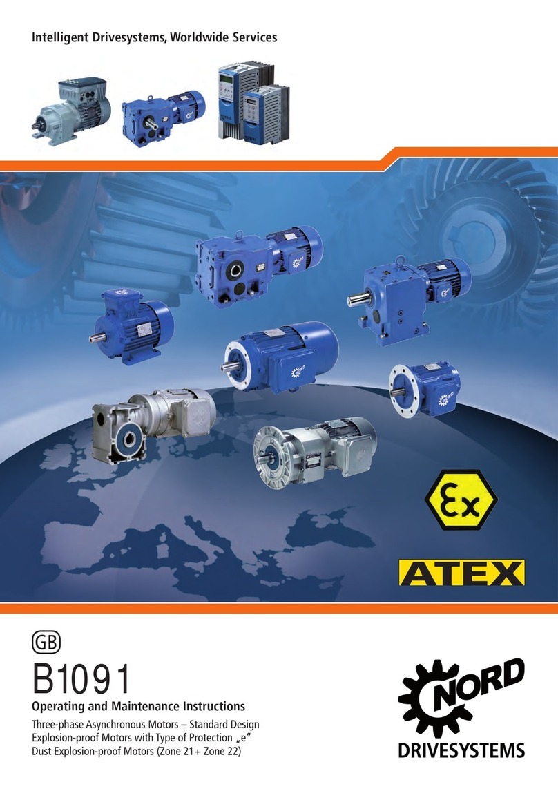
Nord Drivesystems B1091 Specification sheet

B 1091 –en
Motors
Manual with installation instructions

Motors – Manual with installation instructions
2 B 1091 en-1221
Pos: 2 /Anleitungen/M otoren/B1091 Drehstrommotor en/1. Allgemeines/0. Prolog /Sicherheits- und Anwendungs hinweise für Elek tromotoren @ 66\mod_16130480906 52_388.docx @ 2735079 @ @ 1
Safety and operating instructions for electric motors
(according to: Low Voltage Directive 2014/35/EU)
1 General
During operation, devices may, depending on their protection class,
have live, bare, moving or rotating parts or hot surfaces.
Unauthorised removal of covers, improper use, incorrect installation or
operation causes a risk of serious personal injury or material damage.
Further information can be found in this documentation.
All transportation, inst
allation commissioning and maintenance work
must be carried out by qualified personnel (compliant with IEC
364 or.
CENELEC HD 384 or DIN VDE 0100 and IEC 664 or DIN VDE 0110
and national accident prevention regulations).
For the purposes of these basic safety instructions, qualified personnel
are persons who are familiar with the assembly, installation,
commissioning and operation of this product and who have the relevant
qualifications for their work.
2. Proper use in Europe
The devices are components inte
nded for installation in electrical
systems or machines.
When installed in machines, the devices must not be commissioned (i.e.
commencement of the proper use) until it has been ensured that the
machine meets the provisions of the EC Directive 2006/42/EEC
(Machinery Directive); EN 60204 must also be complied with.
Commissioning (i.e. implementation of proper use) is only permitted if
the EMC directive (2014/30/EU) is complied with.
Devices with a CE label meet the requirements of the Low Voltage
Directive 2014/35/EU. The stated harmonized standards for the devices
are used in the declaration of conformity.
Technical data and information for connection conditions can be found
on the r
ating plate and in the documentation, and must be complied
with.
The devices may only be used for safety functions which are described
and explicitly approved.
3. Transport, storage
Information regarding transport, storage and correct handling must be
complied with.
4. Installation
The installation and cooling of the equipment must be implemented
according to the regulations in the corresponding documentation.
The devices must be protected against impermissible loads.
Especially during transport and handling, components must not
be deformed and/or insulation distances must not be changed.
Electrical components must not be mechanically damaged or
destroyed (this may cause a health hazard!).
5. Electrical Connection
When working on live devices, the applicable national accident
prevention regulations must be complied with.
The electrical installation must be implemented according to the
applicable regulations (e.g. cable cross-
section, fuses, earth
lead connections). Furth
er instructions can be found in the
documentation.
Information regarding EMC-compliant installation –
such as
shielding, earthing, location of filters and installation of cables –
can be found in the documentation for the devices. These
instructions must b
e complied with even with CE marked
devices. Compliance with the limiting values specified in the
EMC legal regulations is the responsibility of the manufacturer
of the system or machine.
6. Operation
Where necessary, systems in which the devices are installed
must be equipped with additional monitoring and protective
equipment according to the applicable safety requirements, e.g.
legislation concerning technical equipment, accident prevention
regulations, etc.
The parameterisation and configuration of the devices must be
selected so that no hazards can occur.
All covers must be kept closed during operation.
7. Maintenance and repairs
The following applies in particular for operation with frequency
inverters:
After the devices are disconnected from the power supply, live
equipment components and power connections should not be
touched immediately, because of possible charged capacitors.
Observe the applicable information signs located on the device.
Further information can be found in this documentation.
These safety instructions must be kept in a safe place!

Documentation
B 1091 en-1221 3
Pos: 3 /Anleitung en/Motoren/B1091 Dr ehstrommotoren/1. Allgemeines/0. Prol og/Dokumentation - Versi onsliste [ BU 1091] @ 67\mod_161 3484756730_388. docx @ 2738515 @ @ 1
Documentation
Title:
B 1091
Order no.:
6051302
Series:
Asynchronous motors / synchronous motors
1)
2)
3)
• Single and three-phase asynchronous motors
SK 63*1)/*2) *3) to SK 315*1)/*2) *3)
Power labelling: S, SA, SX, M, MA, MB, MX, L, LA, LB, LX, R, X, Y, A, W
- optionally supplemented with: H, P
Pole number labelling: 2, 4, 6, 8, …
Further options
1)
2)
3)
4)
• Three-phase synchronous motors
SK 63*1)*2)/*3) *4) to SK 132*1)*2)/*3) *4)
Winding version: T, F, …
Power number: 1 to 9
Pole number labelling: 4, 6, 8, …
Further options
1)
2)
3)
• Three-phase asynchronous motors
SK 63*1)/*2) 2D *3) to SK 250*1)/*2) 2D *3)
Power labelling: S, SA, SX, M, MA, MB, MX, L, LA, LB, LX, R, X, Y, A, W
- optionally supplemented with: H, P
Pole number labelling: 4, 6
Options
with ATEX labelling II 2D Ex tb IIIC T . . . °C Db
1)
2)
3)
SK 63*1)/*2) 3D *3) to SK 250*1)/*2) 3D *3)
Power labelling: S, SA, SX, M, MA, MB, MX, L, LA, LB, LX, R, X, Y, A, W
- optionally supplemented with: H, P
Pole number labelling: 4, 6
Options
with ATEX labelling II 3D Ex tc IIIB T . . . °C Dc
1)
2)
3)
SK 63*1)/*2) 2G *3) to SK 200*1)/*2) 2G *3)
Power labelling: S, SA, SX, M, MA, MB, MX, L, LA, LB, LX, R, X, Y, A, W
- optionally supplemented with: H, P
Pole number labelling: 4, 6
Further options
with ATEX labelling II 2G Ex eb IIC T3 Gb
1)
2)
3)
SK 63*1)/*2) 3G *3) bis SK 200*1)/*2) 3G *3)
Power labelling: S, SA, SX, M, MA, MB, MX, L, LA, LB, LX, R, X, Y, A, W
- optionally supplemented with: H, P
Pole number labelling: 4, 6
Further options
with ATEX labelling II 3G Ex ec IIC T3 Gc

Motors – Manual with installation instructions
4 B 1091 en-1221
Version list
Title,
Date
Order number Remarks
B 1091,
January
2015
6051302 / 0215
-
B 1091,
March 2016
6051302 / 1016
• General corrections
• Structural modifications to the document
B 1091
,
December
2016
6051302
/ 4816 • General corrections
B 1091,
June 2017
6051302 / 2417
• Technical supplements
B 1091,
August 2017
6051302 / 3517
• Technical supplements
B 1091,
June 2018
6051302 / 2318
• General corrections
• Update of EU Declaration of Conformity 2D / 3D
B 1091,
August 2018
6051302 / 3118
• General corrections
• Section for operation with frequency inverter removed
• Section for special operating conditions, permissible surrounding
area supplemented
• Ignition protection type labelling and name plates updated
• Update of EU Declaration of Conformity 2G / 3G
B 1091
,
June 2019
6051302
/ 2319 • General corrections
• Update of EU Declaration of Conformity 3D
B 1091,
October
2020
6051302 / 4020
• General corrections
• Supplement with new chapter for use of explosion-protected electric
motors in the People's Republic of China
B
1091March
2021
6051302 / 1221
• General corrections
Pos: 4 /Allgemein/ Allgemeingültig e Module/Urheberrec htsvermerk @ 5\mod_141095508345 9_388.docx @ 150427 @ @ 1
Copyright notice
As an integral component of the device described here, this document must be provided to all
users in a suitable form.
Any editing or amendment or other utilisation of the document is prohibited.
Pos: 5 /Allgemein/ Allgemeingültig e Module/Herausgeber @ 67\m od_1613484928402_388.doc x @ 2738552 @ @ 1
Publisher
Getriebebau NORD GmbH & Co. KG
Getriebebau-Nord-Straße 1 •22941 Bargteheide, Germany •http://www.nord.com
Fon +49 (0) 45 32 / 289-0 •Fax +49 (0) 45 32 / 289-2253
Member of the NORD DRIVESYSTEMS Group
=== Ende der Liste f ürT extmarke Copyright == =

Publisher
B 1091 en-1221 5

Motors – Manual with installation instructions
6 B 1091 en-1221
Pos: 7 /Allg emein/Steuermodul e/Inhaltsv erzeichnis @ 0\mod_13179 78518480_388.doc x @ 4078 @ @ 1
Table of Contents
=== Ende der Liste f ürT extmarke Inhaltsv erzeichnis ===
1General.........................................................................................................................................................8
1.1 Safety and installation notes..............................................................................................................9
1.1.1 Explanation of labels used....................................................................................................9
1.1.2 List of safety and installation notes.....................................................................................10
1.2 Field of use ......................................................................................................................................11
1.3 Correct handling of electric motors ..................................................................................................12
1.3.1 Transport, storage ..............................................................................................................12
1.3.2 Installation ..........................................................................................................................13
1.3.3 Balancing, drive elements ..................................................................................................13
1.3.4 Alignment ...........................................................................................................................14
1.3.5 Output shafts......................................................................................................................14
1.3.6 Electrical connection...........................................................................................................15
1.3.7 Operation with frequency inverter.......................................................................................16
1.3.8 Checking the insulation resistance .....................................................................................17
1.3.9 Commissioning...................................................................................................................17
1.3.10 Disposal..............................................................................................................................18
2Maintenance and servicing ......................................................................................................................19
2.1 Safety measures..............................................................................................................................19
2.2 Bearing replacement periods...........................................................................................................20
2.3Maintenance intervals......................................................................................................................21
2.4 General overhaul .............................................................................................................................21
3ATEX Explosion hazard areas..................................................................................................................22
3.1 Motors with increased ignition protection, type Ex eb ......................................................................22
3.1.1 Cable glands.......................................................................................................................23
3.1.2 Cable connections..............................................................................................................24
3.1.3 Terminal box cover seals....................................................................................................25
3.1.4 Motor position – special features for IM V3, IM V6.............................................................25
3.1.5 Further operating conditions...............................................................................................26
3.1.6 Protective devices ..............................................................................................................26
3.1.7 Operation with frequency inverter.......................................................................................27
3.1.8 Repairs...............................................................................................................................28
3.1.9 Painting ..............................................................................................................................28
3.1.10 Name plate of NORD Ex eb motors according to EN 60079 ..............................................29
3.1.11 Applied standards...............................................................................................................29
3.2 Motors with ignition protection class Non Sparking Ex ec................................................................30
3.2.1 Cable glands.......................................................................................................................31
3.2.2 Cable connections..............................................................................................................31
3.2.3 Terminal box cover seals....................................................................................................32
3.2.4 Motor position – special features for IM V3, IM V6.............................................................32
3.2.5 Further operating conditions...............................................................................................33
3.2.6 Protective devices ..............................................................................................................33
3.2.7 Repairs...............................................................................................................................33
3.2.8 Painting ..............................................................................................................................34
3.2.9 Type plate for NORD Ex ec motors according to EN 60079...............................................35
3.2.10 Applied standards...............................................................................................................35
3.3 Motors for use in Zone 21 and Zone 22 according to EN 60079 and IEC 60079.............................36
3.3.1 Commissioning information / Application area....................................................................37
3.3.2 Terminal box cover seals....................................................................................................38
3.3.3 Electrical Connection..........................................................................................................38
3.3.4 Cable glands.......................................................................................................................38
3.3.5 Permissible ambient temperature range.............................................................................39
3.3.6 Painting ..............................................................................................................................40
3.3.7 IEC-B14 motors..................................................................................................................40
3.3.8 Motor position – special features for IM V3, IM V6.............................................................40
3.3.9 Further operating conditions...............................................................................................41
3.3.10 Design and operating principle...........................................................................................41
3.3.11 Minimum cross section of bonding conductors...................................................................41
3.3.12 Maintenance.......................................................................................................................42
3.4 Options for motors for use in Zone 21 and Zone 22.........................................................................43

Table of Contents
B 1091 en-1221 7
3.4.1 Operation with frequency inverters.....................................................................................43
3.4.2 External fan ........................................................................................................................44
3.4.3 Second temperature sensor 2TF........................................................................................45
3.4.4 Back stop............................................................................................................................45
3.4.5 Brake..................................................................................................................................45
3.4.6 Overview of brake attachment for NORD ATEX motors.....................................................46
3.4.7 Name plate of motors (Ex tb, Ex tc) according to EN 60079 for FI operation .....................47
3.5 Motors according to TP TC012/2011 for the Eurasian Economic Union..........................................48
3.5.1 Type plates / Labelling........................................................................................................48
3.5.2 Standards...........................................................................................................................49
3.5.3 Service life..........................................................................................................................49
3.5.4 Special operating conditions (X-labelling)...........................................................................49
3.6 Motors according to GB 12476.1-2013 / GB 12476.5-2013 for the People's Republic of China ......50
3.6.1 Type plates / Labelling........................................................................................................50
3.6.2 Standards to be observed during operation and maintenance ...........................................51
4Synchronous motors – special information ...........................................................................................52
4.1 Type designation..............................................................................................................................52
4.2 Connection.......................................................................................................................................52
4.3 Encoders..........................................................................................................................................53
4.4 Commissioning ................................................................................................................................53
4.5 Maintenance and servicing ..............................................................................................................53
5Replacement parts....................................................................................................................................54
6Declarations of Conformity ......................................................................................................................55
Pos: 10 /Anleitungen/M otoren/B1091 Drehstromm otoren/1. Allgemeines/!1! Allg emeines @ 7\mod_1431347018514_388.doc x @ 217366 @ 1 @ 1

Motors – Manual with installation instructions
8 B 1091 en-1221
1 General
Pos: 11 /Anleitungen/M otoren/B1091 Drehstromm otoren/1. Allgemeines/!1! Allg emeines_Inhalt @ 7\mod_14313301125 64_388.docx @ 217304 @ @ 1
These operating instructions must be read before NORD motors are transported, installed,
commissioned, serviced or repaired. All persons who are involved in these tasks must observe these
operating instructions. In order to prevent injury or damage, all of the safety information in these
operating instructions must be strictly observed.
The information and instructions in the instructions, safety and commissioning information which is
supplied, as well as all other instructions must be observed.
This is essential to prevent injury and damage.
The applicable national, local and plant-specific regulations and requirements and regulations must be
observed.
Technical details may vary for special designs and constructions. In case of doubt, we urgently
recommend that the manufacturer is contacted, giving details of the type designation and the
motor number.
Qualified personnel are persons who due to their training, experience and instruction, and their
knowledge of the relevant standards, accident prevention regulations and operating conditions are
authorised to carry out the necessary activities.
This also includes knowledge of first aid measures and the local emergency services.
It is assumed that the work for transport, assembly, installation, commissioning, maintenance and
repair will be performed by qualified staff.
In particular, the following must be observed:
• Technical data and information regarding permissible use, installation, connection, ambient and
operating conditions, which are contained in the catalogue, the order documents and other
documentation for the product.
• Local and plant-specific regulations and requirements
• Correct use of tools, lifting and transportation equipment
• Use of personal protective equipment
For reasons of clarity, the operating instructions do not contain detailed information about possible
versions and therefore do not consider all possible cases of installation, operation or servicing.
Because of this, these operating instruction essentially only contain the information which is necessary
for proper use by qualified personnel.
In order to prevent faults it is necessary that the prescribed service and inspection work is carried out
by appropriately qualified personnel.
• For the operation on an inverter, the planning guideline B1091-1 forms a part of these operating
instructions.
• The supplementary operating instructions must be observed if an external fan is present.
• For braking motors, the supplementary brake operating instructions must be observed..
If the operating instructions or the planning guide are lost for any reason, these documents must be
obtained from NORD.
Pos: 12 / Allgemein/Allg emeingültig e Module/----------Seit enumbruch ----------@ 1 \mod_1329145698658_0.doc x @ 15891 @ @ 1

1 General
B 1091 en-1221 9
Pos: 13 /Anleitung en/Elektronik/ FU und Starter/1. Allgemei nes/Sicherheit s- und Installationshi nweise und Warn- Gefahrenhinwei se/Sicherheits - und Installati onshinweise (inkl. Ei nleitung) @ 0\mod_1325780428207_ 388.docx @ 5385 @ 2 @ 1
1.1 Safety and installation notes
The devices are operating materials intended for use in industrial high voltage systems, and are
operated at voltages that could lead to severe injuries or death if they are touched.
The device and its accessories must only be used for the purpose which is intended by the
manufacturer. Unauthorised modifications and the use of spare parts and additional equipment which
has not been purchased from or recommended by the manufacturer of the device may cause fire,
electric shock and injury.
All of the associated covers and protective devices must be used.
Installation and other work may only be carried out by qualified electricians with strict adherence to the
operating instructions. Therefore keep these Operating Instructions at hand, together with all
supplementary instructions for any options which are used, and give them to each user.
Local regulations for the installation of electrical equipment and accident prevention must be complied
with.
Pos: 14 /Anleitung en/Elektronik/ FU und Starter/1. Allgemei nes/Sicherheit s- und Installationshi nweise und Warn- Gefahrenhinwei se/Erläuterung der verwendeten Kennzeic hnungen [B1091] ### ausl aufend ### @ 33\mod_15580763425 33_388.docx @ 2535760 @ 3 @ 1
1.1.1 Explanation of labels used
DANGER Indicates an immediate danger, which may result in death or serious injury.
WARNING Indicates a possibly dangerous situation, which may result in death or
serious injury.
CAUTION Indicates a possibly dangerous situation, which may result in slight or
minor injuries.
NOTICE Indicates a possibly harmful situation, which may cause damage to the
product or the environment.
Note Indicates hints for use and useful information.
Pos: 15 / Allgemein/Allg emeingültig e Module/----------Seit enumbruch ----------@ 1 \mod_1329145698658_0.doc x @ 15891 @ @ 1

Motors – Manual with installation instructions
10 B 1091 en-1221
Pos: 16 /Anleitung en/Elektronik/ FU und Starter/1. Allgemei nes/Sicherheit s- und Installationshi nweise und Warn- Gefahrenhinwei se/Auflistung der Sicher heits- und Installations hinweise @ 1\m od_1341560303401_388.docx @ 30325 @ 3 @ 1
1.1.2 List of safety and installation notes
Pos: 17 /Anleitung en/Motoren/B1091 Dr ehstrommotoren/Si cherheitshinweis e/Gefahr - Elektrisc her Schlag - Motoren [B1091] @ 11\mod_145995 2302755_388.docx @ 316085 @ @ 1
DANGER! Electric shock
The motor is operated with a dangerous voltage. Touching certain conducting components (connection terminals
and supply cables) will cause electric shock with possibly fatal consequences.
Even when the motor is at a standstill (e.g. due to the electronic block of a connected frequency inverter or a
jammed drive unit) the connection terminals and supply cables may carry a dangerous voltage. A motor standstill
is not identical to electrical isolation from the mains.
Even if the drive unit has been disconnected from the mains, a connected motor may rotate and possibly
generate a dangerous voltage.
Installation and work must only be carried out when the motor is at a standstill and is disconnected (all phases
disconnected from the mains).
Follow the 5 Safety Rules (1. Switch off the power, 2. Secure against switching on, 3. Check for no voltage, 4.
Earthing and short circuiting, 5. Cover or fence off neighbouring live components).
Pos: 18 /Anleitung en/Motoren/B1091 Dr ehstrommotoren/Si cherheitshinweis e/Warnung - schwere Last en - Motoren [B1091] @ 11\mod_1460533 620869_388.docx @ 317935 @ @1
WARNING
Hazard due to heavy loads
The large weight of the motor must be taken into account during any transportation or installation work.
Incorrect handling may cause the motor to fall or swing without control and therefore cause severe, and possibly
fatal injuries due to impact, crushing and other physical injuries. In addition, severe damage to the motor and its
surroundings are possible.
Therefore:
– Do not stand under suspended loads
– Only use the attachment points provided
– Check that lifting equipment and lashings have and adequate load capacity and are undamaged
– Avoid hectic movements
– Use personal protective equipment
Pos: 19 /Anleitung en/Motoren/B1091 Dr ehstrommotoren/Si cherheitshinweis e/Warnung - Bewegung - Motor en [B1091] @ 11\mod_1459953068537_3 88.docx @ 316120 @ @ 1
WARNING Injury due to movement
Under certain conditions (e.g. switching on the power supply, releasing a holding brake) the motor may start to
move. The machinery which it drives (press / chain hoist / roller / fan etc.) may then make an unexpected
movement. This may cause various injuries, including to third parties.
Before switching on, secure the danger area by warning and removing all persons from the danger area.
Pos: 20 /Anleitung en/Motoren/B1091 Dr ehstrommotoren/Si cherheitshinweis e/Warnung - lose Teil e - Motoren [B1091] @ 11\mod_1459954601199_38 8.docx @ 316155 @ @ 1
WARNING Hazard due to loose parts
Care must be taken that there are no loose parts on the motor. Otherwise, these may cause injury during
transportation and installation work, or when the motor in in operation.
Loose carrying or lifting eyes may cause the motor to fall during transportation.
Parallel keys on the motor shaft may be thrown out when the motor shaft rotates.
Fasten or remove loose parts and carrying or lifting eyes; secure or remove free parallel shaft keys on the motor
shaft(s).

1 General
B 1091 en-1221 11
Pos: 21 /Anleitung en/Motoren/B1091 Dr ehstrommotoren/Si cherheitshinweis e/Vorsicht - Verbrennungsg efahr @ 11\mod_1460532707435_388. docx @ 317900 @ @ 1
CAUTION
Danger of burns
The surface of the motor may heat up to temperatures in excess of 70°C.
Touching the motor may cause local burns to the affected parts of the body (hands, fingers, etc.).
To prevent such injuries, allow sufficient time for cooling down before starting work - the surface temperature
should be checked with suitable measuring equipment. In addition, keep sufficient distance from adjacent
components during installation, or install protection against contact.
Pos: 22 /Anleitung en/Motoren/B1091 Dr ehstrommotoren/1. Allgemeines/ Anwendungsbereich @ 7\mod_14313307 65571_388.docx @ 217335 @ 2 @ 1
1.2 Field of use
Use of the motors:
The motors may only be used for their intended purpose (to drive machinery).
The motors are constructed with at least protection class IP55 (for the protection class: see rating
plate). They may be installed in dusty or damp environments.
In principle the conditions of use and the ambient conditions determine the necessary protection class
and any other additional measures. For outdoor installation and vertical versions, e.g. V1 or V5 with
the shaft pointing downwards, Getriebebau NORD recommends the use of the double fan cover option
[RDD].
Motors must be protected against intensive sunlight, e.g. by the use of a protective cover. The
insulation is tropicalised.
Installation altitude: ≤ 1000 m
Ambient temperature: -20°C...+40°C
For standard motors an extended ambient temperature range from -20°C...+60°C is permissible.. In
this case, the rated power must be reduced to 82% of the value stated in the catalogue. If the
maximum ambient temperature is between +40°C and +60°C, the power output should be inversely
linearly interpolated between 100% and 82%.
The motor connection cables and the cable glands must be suitable for temperatures ≥ 90°C.

Motors – Manual with installation instructions
12 B 1091 en-1221
Pos: 23 /Anleitung en/Motoren/B1091 Dr ehstrommotoren/1. Allgemeines/ Bestimmungsgemäßer Umgang m it Elektromotoren @ 7\mod_14 31347154915_388.docx @ 217398 @ 2 @ 1
1.3 Correct handling of electric motors
All work must only be carried out with the power to the system switched off.
Pos: 24 /Anleitungen/M otoren/B1091 Drehstromm otoren/1. Allgemeines/Trans port, Einlagerung @ 67\mod_1613401505511_38 8.docx @ 2737482 @ 35 @ 1
1.3.1 Transport, storage
WARNING
Fall hazard
Incorrect handling during transport may result in the motor falling down or swivelling uncontrolledly, and thus
possibly causing serious or fatal injuries such as bruises, contusions and other physical injuries. It may also result
in serious damage to the motor and its environment.
That is why:
– Use the existing threads for ring bolts during transport (see following illustration).
– Do not attach additional loads! The lifting eyes are designed for the motor weight only.
– For transporting the machine units (e.g. gear unit attachments), only use the lifting eyes and pins provided
for this purpose!
– Machine units must not be lifted by attaching them to the individual machines!
To avoid any damage to the motor, the motor must always be lifted via suitable lifting equipment. If the
period between delivery and motor commissioning is more than four years under favourable conditions
(storage in dry and dust-free spaces protected from vibrations), the roller bearings should be replaced.
Unfavourable conditions significantly reduce the period. If necessary, unprotected and finished
surfaces (flange surface, shaft end, ...) may be treated with corrosion protection agents. If necessary,
the winding’s insulation resistance must be checked (1.3.8 "Checking the insulation resistance").
Changes compared to normal operation (increased power consumption, higher temperatures or
vibrations, unusual noises or odours, response of monitoring systems, etc.) may indicate that the
function is impaired. To avoid personal injury or material damage, the maintenance staff responsible
must be informed of these changes without delay.
In case of doubt, switch off the motor immediately as soon as this is allowed by the system’s state.
Mounting of ring bolts for transport
The number, position and thread size of the ring bolts provided for transport varies depending on the
motor size.
Size Threads Position
63
…
…
71
…
…
80
M6
2, 4
90
M8
1, 2, 3, 4
100
M8
1, 2, 3, 4
100 APAB
M8
2, 4
112
M8
1, 2, 3, 4
132 M10 1, 2, 3, 4
160
M12
1, 2, 3, 4
180
M12
1, 2, 3, 4
200X
M12
1, 2, 3, 4
Pos: 25 /Anleitung en/Motoren/B1091 Dr ehstrommotoren/1. Allgemeines/ Aufstellung @ 7\mod_1431348785190 _388.docx @ 217460 @ 3 @ 1

1 General
B 1091 en-1221 13
1.3.2 Installation
• After installation, screwed-on lifting lugs must be tightened or removed.
• Smooth running: Precise alignment of the clutch and a well-balanced drive element (clutch, pulleys,
fan, etc.) are prerequisites for smooth vibration-free running.
• Complete balancing of the motor and the drive elements may be necessary.
• The top section of the terminal box and the position of the terminal box can be rotated by 4 x 90
degrees.
• Even if not required, on IEC B14 motors all four fixing screws, must be screwed into the flanged
bearing plate! The fixing screw threads must be inserted with a sealant, e.g. Loctite 242.
WARNING
Electric shock
The maximum depth for screwing into the type plate is 2x d. There is a danger that the motor windings may be
damaged if longer screws are used. This creates a danger of potential transfer to the housing and danger of
electric shock if touched.
• The motor must be inspected for damage before installation and commissioning. A damaged motor
must not be commissioned.
• Rotating shaft ends and unused shaft ends must be protected against contact. Unused parallel
shaft keys must be secured against being thrown out.
• The motor must be suitable for the installation location. (requirements prescribed by standards,
ambient conditions, installation altitude)
• Motor surfaces may become very hot during operation. Suitable protective measures must be
taken if there is a danger of contact or a hazard to the vicinity of the installation.
Pos: 26 /Anleitung en/Motoren/B1091 Dr ehstrommotoren/1. Allgemeines/Wuc htung, Abtriebselem ente @ 7\mod_1431349031782_3 88.docx @ 217491 @ 3 @ 1
1.3.3 Balancing, drive elements
The fitting and removal of drive elements (clutch, pulley, gear wheel,…) must be performed with
suitable equipment. As standard the rotors are balanced with half key balancing. The appropriate
form of balancing must be observed if drive elements are installed on the motor shaft. Drive
elements must be balanced according to ISO 1940.
The generally required measures for protection against touching the drive elements must be observed.
If a motor is started without a drive element, the parallel key must be secured against being thrown
out. This also applies for any second shaft end. Alternatively, the parallel shaft key must be removed.

Motors – Manual with installation instructions
14 B 1091 en-1221
Pos: 27 /Anleitung en/Motoren/B1091 Dr ehstrommotoren/1. Allgemeines/ Ausrichten @ 7\mod_1431349204216_38 8.docx @ 217522 @ 3 @ 1
1.3.4 Alignment
In particular with direct coupling, the motor shafts and the driven machine must be axially and radially
aligned to each other. Incorrect alignment may result in damage to the bearings, excessive vibration
and breakage of the shaft.
Pos: 28 /Anleitung en/Motoren/B1091 Dr ehstrommotoren/1. Allgemeines/ Abtriebswellen @ 64\mod_161192260 5855_388.docx @ 2726037 @ 3 @ 1
1.3.5 Output shafts
The maximum permissible axial (FA) and radial forces (FR) for the A side end of the motor shaft can be
obtained from the table below. Getriebebau NORD should be consulted if the radial force (FR) is
applied at a distance which is greater than the length E/2.
Type
F
R
[N]
F
A
[N]
63
530
480
71
530
480
80
860
760
90
910
810
100
1300
1100
112
1950
1640
132
2790
2360
160
3500
3000
180 .X
3500
3000
180
5500
4000
200 .X
5500
4000
225
8000
5000
250
8000
5000
No axial (FA) and radial forces (FR) are permissible for the B side shaft end.
NOTICE! Attachments must not cause rubbing (danger of excessive temperatures and sparking) or
impair the necessary flow of cooling air.
Pos: 29 / Allgemein/Allg emeingültig e Module/----------Seit enumbruch ----------@ 1\mod_13291 45698658_0.docx @ 15891 @ @1

1 General
B 1091 en-1221 15
Pos: 30 /Anleitung en/Motoren/B1091 Dr ehstrommotoren/1. Allgemeines/ Elektrischer Anschluss @ 10\mod_1455530538031_388. docx @ 299682 @ 3 @ 1
1.3.6 Electrical connection
The connection cables must be passed through the cable glands in the terminal box. The terminal box
must be sealed against dust and water. The mains voltage and frequency must conform to the data on
the rating plate. ±5 % voltage or ±2 % frequency deviations are permissible without reduction of the
power. The connection and configuration of the jumpers must be made according to the circuit
diagram in the terminal box.
Please refer to the following table for the labelling of the auxiliary terminals
Auxiliary terminal designation
Additional equipment
Labelling of auxiliary terminals
Comments
New: EN 60034-8
Thermistor
TP1 – TP2
1TP1 – 1TP2
2TP1 – 2TP2
3TP1 – 3TP2
4TP1 – 4TP2
Switch-off
Warning Winding 1
Switch-off Winding 1
Warning Winding 2
Switch-off Winding 2
Option: TF 5TP1 – 5TP2 Brake
Bi-metal temperature sensor
Normally closed
Option: TW
1TB1 –1TB2
2TB1 –2TB2
3TB1 –3TB2
4TB1 –4TB2
Warning Winding 1
Switch-off Winding 1
Warning Winding 2
Switch-off Winding 2
Bi-metal temperature sensor,
normally open
1TM1 – 1TM2
2TM1 – 2TM2
3TM1 – 3TM2
4TM1 – 4TM2
Warning Winding 1
Switch-off Winding 1
Warning Winding 2
Switch-off Winding 2
PT100
1R1 – 1R2
2R1 – 2R2
3R1 – 3R2
Winding 1 (Phase U)
Winding 1 (Phase V)
Winding 1 (Phase W)
KTY
Silicon temperature sensor (+) 4R1 – 4R2 (-)
(+) 5R1 – 5R2 (-) Winding 1
Winding 2
Standstill heating
Option: SH
1HE1 – 1HE2
2HE1 – 2HE2
Motor heater
Brake heater
Capacitor
Motor version:
EAR/EHB/EST
1CA1 – 1CA2
2CA1 – 2CA2
3CA1 – 3CA2
4CA1 – 4CA2
with operating capacitor 1
with operating capacitor 2
with starting capacitor 1
with starting capacitor 2
Direct current brake
Option: BRE...
BD1 – BD2
Option: DBR… Brake1: BD1-BD2
Break2: BD3-BD4
Pos: 31 /Allgem ein/Allgemeing ültige Module/ ----------Seitenumbruc h ----------@ 1\mod_132914569 8658_0.docx @ 15891 @ @ 1

Motors – Manual with installation instructions
16 B 1091 en-1221
Pos: 32 /Anleitung en/Motoren/B1091 Dr ehstrommotoren/1. Allgemeines/ Betrieb am Frequenzumric hter @ 64\mod_1612254091330_388. docx @ 2727030 @ 3 @ 1
1.3.7 Operation with frequency inverter
Type SK 63 ./. – SK 250 ./. three phase asynchronous motors are qualified for operation with link
circuit inverters according to DIN EN 60034-18-41 (2014).
Please also observe the operating instructions for the frequency inverter which is used.
The insulation system used by NORD consists of suitable varnished copper wire, phase insulation,
homogeneous impregnation and groove lining as insulation against earth, and in the standard version
is designed for the increased requirements for link circuit inverters.
The maximum permissible FI input voltage is 500 V +10%. Link circuit voltages in excess of 750 V DC
are not permissible. When the motor is warm due to operation, the peak voltages due to the system,
the inverter, the cable or the motor must not exceed the following values.
If the values are outside of the permissible range, du/dt or sine wave filters may be used (not the
additional voltage drop).
The cable lengths shown in the diagram are for guidance only and may deviate according to the
specific conditions.
For additional information for operation with a frequency inverter, especially with regard to information
about the maximum speed, thermal design and possible torques, please refer to the current NORD
motor catalogue M7000.
Permissible impulse voltages depending on voltage rise-time
Impulse voltage [V]
Voltage rise time [µs]

1 General
B 1091 en-1221 17
Pos: 33 /Anleitung en/Motoren/B1091 Dr ehstrommotoren/1. Allgemeines/ Überprüfung des Isolat ionswiderstandes @ 7\mod_143135 3806825_388.doc x @ 217716 @ 3555 @ 1
1.3.8 Checking the insulation resistance
Prior to initial commissioning of the motor after a long period of storage or standstill (approx. 6
months) the insulation resistance of the windings must be checked. During and immediately after the
measurements, the terminals have voltages which can be dangerous, and must not be touched.
Insulation resistance
The insulation resistance of new, cleaned, repaired windings against the housing and against each
other is > 200 MΩ.
Measurement
The insulation of the windings against the housing for operation voltages up to 400 V must be
measured with 500 V DC. For operating voltages up to 725 V the measurement must be made with
1000 V DC. The temperature of the windings should be 25°C ± 15°C.
Testing
If the minimum insulation resistance of the winding against earth is less than 50 MΩ, this may be due
to moisture. The windings must then be dried.
The insulation resistance may reduce after long periods of operation. As long as the measured value
does not fall below the calculated value for the critical insulation resistance of < 50 MΩ, operation of
the motor may continue. If the value is less than this, the cause must be established and if necessary
the windings or parts of the windings must be repaired, cleaned or dried.
Pos: 34 /Anleitung en/Motoren/B1091 Dr ehstrommotoren/1. Allgemeines/Inbet riebnahme @ 7\mod_143135407379 5_388.docx @ 217747 @ 3 @ 1
1.3.9 Commissioning
Information
Electromagnetic compatibility
NORD motors comply with the EU-Directive 2014/30/EU. Assembly or installation work must not cause
impermissible interference. Immunity from interference must still exist.
Production of interference: In cases of large differences of torque (e.g. when driving a piston
compressor) a non-sine wave motor current is induced, whose harmonics can cause an impermissible
effect on the mains and therefore impermissible production of interference.
With supply by frequency inverters, various strengths of interference are produced according to the
design of the frequency inverter (type, interference suppression, manufacturer). The EMC information
of the inverter manufacturer must be observed. If a shielded motor supply cable is recommended, the
shielding is most effective if a large area is electrically connected to the metal terminal box of the
motor (with metal EMC cable gland). With motors with integrated sensors (e.g. thermistors)
interference voltages due to the inverter may be produced in the sensor cables.

Motors – Manual with installation instructions
18 B 1091 en-1221
Interference immunity: For motors with integrated sensors (e.g. thermistors) the operator must
ensure adequate immunity to interference by the selection of a suitable sensor cable (possibly with
screening, with connection as for the motor supply cable) and evaluation device. The information and
instructions in the operating instructions for the inverter and all other instructions must be observed
before commissioning. After installation of the motor, it must be checked for correct functioning. In the
case of brake motors, the correct function of the brake must also be checked.
Pos: 35 /Anleitung en/Motoren/B1091 Dr ehstrommotoren/1. Allgemeines/ Entsorgung @ 7\mod_1431354230589_ 388.docx @ 217778 @ 3 @ 1
1.3.10 Disposal
NOTICE Environmental damage
Incorrect disposal of the product may cause damage to the environment.
• Ensure correct disposal
• Comply with current local regulations
Content: aluminium, iron, electronic components, copper
Please observe the additional documentation for the attachments
Pos: 37 /Anleitung en/Motoren/B1091 Dr ehstrommotoren/2. Instandhaltung, War tung/!1! Instandhal tung und Wartung @ 7\mod_143135 4436983_388.docx @ 217809 @ 1 @ 1

2 Maintenance and servicing
B 1091 en-1221 19
2 Maintenance and servicing
Pos: 38 /Anleitung en/Motoren/B1091 Dr ehstrommotoren/Si cherheitshinweis e/Gefahr - Elektrisc her Schlag - Motoren [B1091] @ 11\mod_145995 2302755_388.docx @ 316085 @ @1
DANGER!
Electric shock
The motor is operated with a dangerous voltage. Touching certain conducting components (connection terminals
and supply cables) will cause electric shock with possibly fatal consequences.
Even when the motor is at a standstill (e.g. due to the electronic block of a connected frequency inverter or a
jammed drive unit) the connection terminals and supply cables may carry a dangerous voltage. A motor standstill
is not identical to electrical isolation from the mains.
Even if the drive unit has been disconnected from the mains, a connected motor may rotate and possibly
generate a dangerous voltage.
Installation and work must only be carried out when the motor is at a standstill and is disconnected (all phases
disconnected from the mains).
Follow the 5 Safety Rules (1. Switch off the power, 2. Secure against switching on, 3. Check for no voltage, 4.
Earthing and short circuiting, 5. Cover or fence off neighbouring live components).
Pos: 39 /Anleitung en/Motoren/B1091 Dr ehstrommotoren/Si cherheitshinweis e/Warnung - Bewegung - Motoren [ B1091] @ 11\mod_1459953068537_388. docx @ 316120 @ @ 1
WARNING Injury due to movement
Under certain conditions (e.g. switching on the power supply, releasing a holding brake) the motor may start to
move. The machinery which it drives (press / chain hoist / roller / fan etc.) may then make an unexpected
movement. This may cause various injuries, including to third parties.
Before switching on, secure the danger area by warning and removing all persons from the danger area.
Pos: 40 /Anleitung en/Motoren/B1091 Dr ehstrommotoren/2. Instandhaltung, War tung/Sicherheit smaßnahmen @ 7\mod_143135450019 8_388.docx @ 217840 @ 2 @ 1
2.1 Safety measures
Before starting any work on the motor or the device, but especially before opening the covers of active
components, the motor must be isolated according to regulations. In addition to the main power
circuits, any additional or auxiliary circuits must be taken into account.
The usual "5 Safety Rules" e.g. according to DIN VDE 0105 are:
• Disconnect
• Secure to prevent reactivation
• Check for no voltage on all poles
• Earth and short circuit
• Cover or cordon off adjacent live components
These measures may only be removed when the maintenance work is complete.

Motors – Manual with installation instructions
20 B 1091 en-1221
Motors must be properly inspected at regular intervals; current national standards and regulations
must be complied with. In particular, special attention must be paid to any mechanical damage, free
path of the cooling air, abnormal noises and correct electrical connection.
Only original parts may be used as spare parts with the exception of standardised, commercially
available and equivalent parts.
Swapping parts between motors of the same type is not permissible.
Information
Condensation outlets
If the motors are designed with closed condensation outlets, these must be opened occasionally in order to allow
any accumulated condensation to drain off. Condensation outlets must always be located at the lowest point of
the motor. During installation of the motor care must be taken that the condensation outlets point downwards and
are closed. Open condensation outlets cause a reduction of the protection class.
Pos: 41 /Anleitung en/Motoren/B1091 Dr ehstrommotoren/2. Instandhaltung, War tung/Lagerwec hselfristen @ 67\mod_1613485099 782_388.docx @ 2738589 @ 2 @ 1
2.2 Bearing replacement periods
Under normal operating conditions, with horizontal motor installation, the bearing replacement period
in operating hours [h] for IEC motors is the following depending on the listed coolant temperature and
motor speeds:
25°C 40°C 60°C
to 1,800 min-1
approx. 40,000 h
approx. 20,000 h
approx. 8,000 h
to 3,600 min-1
approx. 20,000 h
approx. 10,000 h
approx. 4,000 h
In case of direct mounting of the gear units or special operating conditions, for example vertical motor
installation, high vibration and impact loads, frequent reversing operation, etc., the above-mentioned
operating hours can be significantly reduced.
Pos: 42 / Allgemein/Allg emeingültig e Module/----------Seit enumbruch ----------@ 1 \mod_1329145698658_0.doc x @ 15891 @ @ 1
Other manuals for B1091
1
Table of contents
Other Nord Drivesystems Engine manuals
Popular Engine manuals by other brands

YANGDONG
YANGDONG Y90 Series Operation & maintenance manual
Subaru
Subaru EH025 Instructions for use
Mercury
Mercury MerCruiser Tow Sport 5.7 LHS manual
MTD
MTD SX800 owner's manual
Siemens
Siemens SIMOTICS TN N-compact 1LH8 Operating instructions & installation instructions

Nakayama
Nakayama SP9700 user manual
