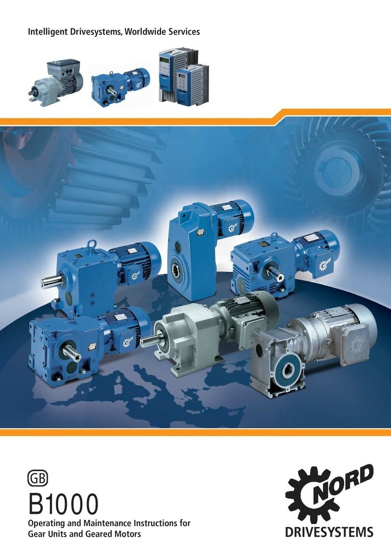
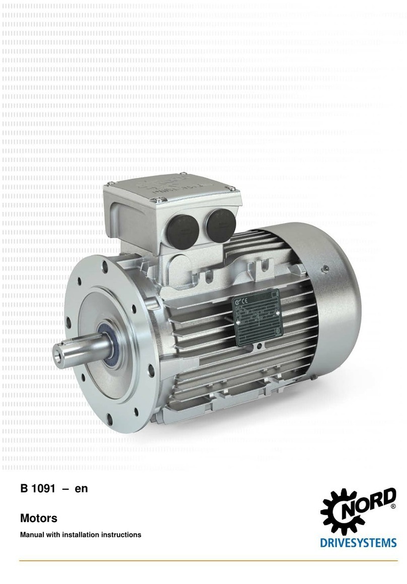
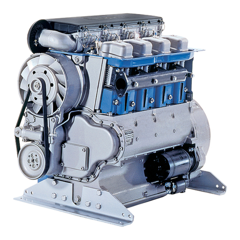
Nord Drivesystems B1091 Manual

Intelligent Drivesystems, Worldwide Services
B1091
Operating and Maintenance Instructions
GB
Three-phase Asynchronous Motors – Standard Design
Explosion-proof Motors with Type of Protection „e“
Dust Explosion-proof Motors (Zone 21+ Zone 22)

-2- B1091-GB-3212 www.nord.com
Contents
1. General information ........................................................................................................... 3
2. Description............................................................................................................................4
2.1 Range of application...............................................................................................................4
3. Information on the designated use of electric motors ....................................................4
3.1 Transport, storage..................................................................................................................4
3.2 Installation...............................................................................................................................5
3.3 Balancing, output components...............................................................................................5
3.4 Alignment................................................................................................................................5
3.5 Electrical connection...............................................................................................................5
3.6 Checking insulation resistance...............................................................................................6
3.7 Commissioning.......................................................................................................................6
4. Maintenance/servicing.........................................................................................................7
5. Motors with type of protection Increased Safety Exe.......................................................8
6. Motors for use in Zone 21 and Zone 22............................................................................10
6.1 General.................................................................................................................................10
6.2 Safety instructions................................................................................................................10
6.3 Commissioning instructions/range of application.................................................................10
6.4 Design and method of operation ..........................................................................................11
6.5 Minimum cross-sections of protective earth wires................................................................11
6.6 Maintenance.........................................................................................................................12
7. IE2-ATEX Motors for use in Zone 21 and Zone 22 ..........................................................13
7.1 General information..............................................................................................................13
7.1.2 Impact test............................................................................................................................13
7.2 Safety information.................................................................................................................13
7.3 Commissioning information / Field of application / Extended ambient temperature range...........13
7.3.1 Electrical connection.............................................................................................................14
7.3.2 Cable and wiring glands.......................................................................................................15
7.3.3 Permissible ambient temperature range ..............................................................................16
7.3.4 Painting.................................................................................................................................16
7.3.5 IEC-B14 Motors....................................................................................................................16
7.4 Structure and method of use................................................................................................17
7.5 Minimum cross section of bonding conductors ....................................................................17
7.6 Maintenance.........................................................................................................................17
8. Options for motors for use in Zone 22.............................................................................18
8.1 Option inverter operation......................................................................................................18
8.2 Option external fan...............................................................................................................18
8.3 Option return stop.................................................................................................................18
8.4 Option brake.........................................................................................................................18
9. Spare parts drawing and spare parts list.........................................................................19
10. Conformity declarations....................................................................................................20
Safety and information signs
Please comply with the following safety and information signs!
Danger!
Danger to life and risk of
injury for humans
Attention!
Damage to the machine possible
Danger!
Important information
for explosion protection
Information!

www.nord.com B1091-GB-3212 -3-
1. Information
1. General information
These Operating Instructions must be read before you transport, assemble, commission,
maintain or repair NORD motors. All persons who are involved with such tasks must observe
these Operating Instructions. All safety instructions provided in these Operating Instructions
must be strictly observed for reasons of personal protection and protection of property.
Information and instructions provided in the manual supplied, safety and commissioning
information and all other manuals must be observed.
This is absolutely essential in order to avoid hazards and damage!
Any applicable national, local and system-specific regulations and requirements must also be
observed!
Custom designs and design variants may differ on technical details. If any points are
not clear, it is urgently recommended that you consult the manufacturer stating the
type designation and motor number or have the maintenance work performed by
NORD.
Qualified staff are persons who, owing to their training, experience, instruction received, and
their knowledge of relevant standards, accident prevention regulations and the appropriate
operating conditions, are entitled to perform the activities necessary in order to put the motor
into operation.
That also calls for knowledge of First Aid and local rescue facilities. It is assumed that the
work for transport, assembly, installation, commissioning, maintenance and repair will be
performed by qualified staff.
The following points in particular must be observed:
Specifications and information about permissible use, assembly, connection, ambient
and operating conditions, which are included in the catalogue, the order
documentation and any other product documentation
The local, system-specific regulations and requirements
Expert use of tools, hoisting equipment and transport equipment
Use of personal safety equipment
For reasons of simplicity the Operating Instructions cannot contain all detailed information
about possible design variants so they cannot take into consideration every imaginable case
of installation, operation or maintenance.
For this reason these Operating Instructions essentially only contain such instructions as are
required for normal use by qualified staff. To prevent malfunctions it is necessary that the
specified maintenance and inspection work be performed by appropriately trained staff.
The engineering guideline 605 2101 must be included with the operating instructions
when operated with the inverter.
The additional operating instructions must be taken into account if an external fan is
present.
The brake operating instructions must also be taken into account with braking motors.
If, for any reason, the operating instructions or the engineering guidelines are lost, new
documentation must be obtained from Getriebebau NORD.

-4- B1091-GB-3212 www.nord.com
2. Description
3. Information
2.1 Range of application
Use of the motors:
The motors may only be used for their intended purpose.
The motors are designed with at least IP 55 protection (for degree of protection see name
plate). They can be installed in a dusty or moist environment.
The necessary degree of protection and any additional precautions required always depend
on the operating and environmental conditions. For outdoor installation and vertical designs,
e.g. V1 or V5 with shaft pointing down, NORD recommends using the option of the double fan
hood [RDD].The motors must be protected against intense sunlight, e.g. by means of a
protective roof. The insulation is tropic-proof.
Installation height: 1000 m
Ambient temperature: -20°C...+40°C. With standard motors, a greater ambient temperature
range is permitted from -20°C...+60°C. The rated power must however be reduced to 82% of
the catalogue value. If the maximum value of the ambient temperature is between +40°C and
+60°C, the value of the power consumption can be inversely interpolated linearly between
100% and 82%.
The motor connection cables and the cable inlet glands must be suitable for temperatures
90°C.
3. Information on the designated use of electric motors
Work may only be performed if the system is disconnected from the mains supply.
3.1 Transport, storage
For transport use all the hoisting lugs fitted to the motor!
The hoisting lugs are designed for the weight of the motor; do not attach any
additional loads!
To transport machine sets (e.g. gear unit attachments) only use the hoisting lugs and
pins provided!
Machine sets must not be hoisted by attaching to individual machines!
To prevent damage to the motor, the motor must always be lifted with suitable hoisting
equipment. The antifriction bearings should be replaced if the time between delivery and
motor commissioning under favourable conditions (storage in dry, dust-free and vibration-free
rooms) is more than 4 years. Under unfavourable conditions that time is reduced
considerably. It may be necessary to treat unprotected, machine surfaces (flanging surface,
shaft end; ...) with corrosion inhibitor. If necessary, check the insulation resistance of the
winding, see section 3.6.
Changes in normal operation (higher power consumption, higher temperatures or higher
vibrations, unusual noises or smells, response from the monitoring system, etc.) indicate that
operation is impaired. To avoid personal injury and damage to property, the maintenance staff
responsible must be informed about the change immediately.
In case of doubt switch off the motor without delay, as soon as the status of the system
permits.

www.nord.com B1091-GB-3212 -5-
3. Information
3.2 Installation
Screwed-in lifting eyes must either be screwed in fully or removed after erection!
Running smoothness: Precise alignment of the coupling and a well-balanced drive
element (coupling, belt pulleys, fans, etc.) are prerequisites for quiet, low vibration
operation.
Complete balancing of the motor with the drive elements may be necessary.
The upper section of the terminal box and the terminal box position can be rotated by
4 x 90 degrees.
IEC-B14 motors:
All four fixing screws, even if not required, must be screwed into the flanged bearing
plate! The fixing screw threads must be inserted with a sealant, e.g. Loctite 242. The
maximum screw-in depth in the bearing plate is 2 x d.
The motor must be inspected for damage before installation and commissioning. A
damaged motor must not be commissioned.
3.3 Balancing, output components
Fitting and removing output assemblies (coupling, pulleys, gear, ...) must be performed
with a suitable device. The rotors are balanced with half key balancing as standard.
When fitting output assemblies to the motor shaft observe the appropriate type of
balancing! The output assemblies have to be balanced in accordance with
DIN ISO 1940!
Take the general precautions necessary for providing the output assemblies with shock
protection. If a motor is put into operation without an output assembly, prevent the key from
being flung out. This also applies if a second shaft end is fitted. Alternatively, remove the key.
3.4 Alignment
Especially if there is a direct coupling, align the shafts of the motor and the driven machine
with one another axially and radially. Any inaccurate alignment can lead to bearing damage,
excessive vibrations and shaft breakage.
3.5 Electrical connection
Feed the connecting leads into the terminal box with cable glands. The terminal box must be
sealed so that it is dust-tight and water-tight. The mains voltage and mains frequency must
agree with the figures on the name plate. ± 5% voltage deviations or ± 2% frequency
deviations are permissible without any reduction in performance. The connections and
arrangement of the terminal board jumpers must conform to the circuit diagram provided in
the terminal box. Connect the protective earth lead to that protective earth terminal.
Provide the ends of the connecting leads with cable lugs or curved ring eyes and connect
them to the terminal board. That also applies to the protective earth connection and the
external bonding lead.
For tightening torques at the screw connections of electric terminals and the terminal board
connections (apart from terminal strips) refer to the table below:
Tightening torques for terminal board connections
Thread diameter M4 M5 M6 M8
Tightening torque (Nm) 0.6 – 1.2 1.8 – 2.5 2.7 – 4.0 5.5 – 8.0
If the machine has an auxiliary heater, it must not be switched on during operation.

-6- B1091-GB-3212 www.nord.com
3. Information
3.6 Checking insulation resistance
Before putting the motor into operation for the first time, after a lengthy period of storage or
standstill (approx. 6 months), the insulation resistance of the winding has to be determined.
During and directly after measurement the terminals carry hazardous voltages in some cases
and must not be touched.
Insulation resistance
The insulation resistance of new, cleaned, repaired windings against the housing and against
one another is >200 M Ohm.
Measurement
In the case of windings up to an operating voltage of 400 V the insulation resistance against
the housing must be measured with a DC voltage of 500 V. At operating voltages up to 725 V
measure with a DC voltage of 1000 V. When doing this the temperature of the windings
should be 25°C ± 15°C.
Checking
If, in the case of a new, cleaned winding or a repaired motor which has been stored or shut
down for any lengthy period, the insulation resistance of the winding against the housing is
less than 50 MOhm, the cause may be moisture. The windings will then have to be dried.
After any lengthy period of operation the insulation resistance may drop. As long as the
measured value does not fall below the critical insulation resistance of < 50 MOhm, the motor
may continue to be operated. If the value falls below the critical level, the cause must be
established and if necessary, the windings or winding sections must be repaired, cleaned or
dried.
3.7 Commissioning
Note: Electromagnetic compatibility
Emitted interference: If torques are not equal (e.g. drive of a piston compressor) a non-
sinusoidal motor current is bound to develop, the harmonics of which may cause
impermissible mains influence and hence impermissible emitted interference.
If power is fed via an inverter, different levels of emitted interference will occur, depending on
the design of inverter (type, suppression, manufacturer). It is absolutely essential that the
EMC information provided by the inverter manufacturer be observed. If the manufacturer
recommends a screened motor supply lead, screening will be most effective if it is electrically
connected to a large area of the metal terminal box of the motor (with EMC cable gland made
of metal). In the case of motors with built-in sensors (e.g. PTC thermistors) interference
voltages can occur on the sensor line, caused by the inverter.
Interference immunity: In the case of motors with built-in sensors (e.g. PTC thermistors) the
user himself must ensure adequate interference immunity by making a suitable selection of
sensor signal line (possibly with screening, interfacing as with motor supply lead) and the
analysing instrument. Prior to commissioning always observe the information and instructions
in the operating manuals for inverters as well as all other sets of instructions. After attaching
the motors, check them to make sure they are operating properly! In the case of brake motors
also check that the brake operates properly.

www.nord.com B1091-GB-3212 -7-
4. Maintenance
Servicing
Safety precautions
Before commencing any work on the motor or device, but especially before opening covers in
front of live components, always isolate the motor electrically according to the regulations.
Apart from the main circuits also isolate any additional or auxiliary circuits.
The standard "5 safety rules", e.g. according to DIN VDE 0105, are:
Isolate electrically
Prevent equipment from being switched on again
Check that there is no voltage
Earth and short-circuit
Cover any adjacent live components or prevent access with barriers
The above precautions may only be withdrawn when the maintenance work has been
completed and the motor is fully assembled.
Inspect the motors properly at regular intervals. In particular look out for any physical damage,
ensure that cooling passages are free, listen for any unusual noises, and ensure that electrical
connections are performed in a proper manner.
With the exception of standardised, commercial or equivalent parts the only spare parts which
may be used are genuine spare parts!
NOTE: Inasmuch as motors are provided with enclosed condensation ports, they must be
opened from time to time so that any accumulated condensation can drain off. Condensation
ports are always positioned at the lowest point of the motor. When installing the motor ensure
that the condensation holes are at the bottom.
Bearing changes, grease filling
The period for changing bearings in operating hours [h] on IEC motors with coupling drive is
as follows, under normal operating conditions and with the motor installed horizontally,
depending on coolant temperature and motor speed:
25°C 40°C
up to 1800 min-
1
approx. 40000 h approx. 20000 h
up to 3600 min-
1
approx. 20000 h approx. 10000 h
In the case of direct gearbox attachment or under special operating conditions, e.g. vertical
motor, substantial vibrations or shock loads, frequent reversing, etc. the above-mentioned
operating hours will be reduced considerably.
The motor must be subjected to a general overhaul every 5 years!
General overhaul
For this purpose the motor must be dismantled. Perform the following work:
Clean all parts of the motor
Inspect all parts of the motor for damage
Replace all damaged parts
Replace all antifriction bearings
Replace all gaskets and shaft seals
The general overhaul must be performed in a specialised workshop with appropriate
equipment and by qualified staff. We urgently recommend having the general overhaul
performed by NORD Service.

-8- B1091-GB-3212 www.nord.com
5. Motors with protection type
Increased Safety Exe
These motors are subject to the following supplementary or specific information.
The motors are suitable for use in Zone 1 and conform to equipment group II, category 2G, and can be used
for an ambient temperature between -20°C and +40°C.
Type addition: 2G e.g.: 80 L/4 2G TF
The marking is 0102 II 2G Ex e II along with the temperature class
If the motor is connected to a gearbox, the Ex marking of the gearbox must also be observed.
Explosive gas mixtures or concentrations of dust in conjunction with hot, live and moving parts on electrical
machinery can cause serious or lethal injuries.
The increased hazard in explosive areas calls for particularly careful compliance with the general safety and
commissioning instructions. The staff responsible must be trained regarding correct use of motors in
explosive areas.
Explosion-proof electrical machines comply with the standards in series EN 60034 (VDE 0530) as well as
EN 60079-0 and 60079-7. It is the degree of explosion risk which determines zone classification.
DIN EN 60079, Part 10, provides information on this. It is the user who is responsible for zone classification.
If motors are not certified for explosive areas, it is prohibited to use them in explosive areas.
Cable entries must be approved for explosive atmospheres. Ports which are not used must be closed off with
approved blind plugs.
When connecting up the installation lines to the motor terminals and the protective earth lead must be laid
with U-shaped lines under the respective terminals so that the wire clamps and the terminal studs are
subjected to uniform loading and are not deformed under any circumstances. Alternatively, the connections
can be made with a cable lug. The use of aluminium connecting cables is not permissible.
The motor is supplied with a certified cable gland. The clamping nuts of the cable gland must be tightened to
the torque specified in the following table.
Cable gland Clamping nut tightening
torque [Nm]
M20x1.5 6
M25x1.5 8
M32x1.5 12
M40x1.5 16
When connecting up always ensure that the permissible clearance distances of 10 mm and the permissible
creepage distances of 12 mm between live components and housing potential and between individual live
components are observed.
Before the terminal box is closed, make sure that all the nuts on the terminals and the screw on the
protective earth terminal are tight. The terminal box gaskets and the seals on the cable gland must be fitted
properly and must not be damaged in any way.
If the shaft end is at the top, e.g. designs IMV3 or IMV6, and the motor has Exe protection, the user/installer
must fit a cover which prevents foreign bodies from falling into the motor fan hood (see DIN EN 60079-0). It
must not impair cooling of the motor by its fan. A handwheel at the second shaft end is not permitted. If the
shaft end is at the bottom, e.g. designs IMV1 or IMV5, the motors are generally provided with a protective
roof on the fan hood. The motors are designed for continuous duty and normal, non-recurring start-ups in
which no substantial start-up heat develops.
Area A in EN 60034-1 (VDE 0530 Part 1) - voltage ± 5%, frequency ± 2%, characteristic, mains symmetry -
must be observed so that the development of heat remains within the limits permitted. Any major deviations
from the ratings can caused an impermissible increase in the development of heat in the electric machine.
The motor temperature class stated on the name plate must at least conform to the temperature class of any
combustible gas that may be emitted.

www.nord.com B1091-GB-3212 -9-
5. Motors with protection type
Increased Safety Exe
Each machine must be protected against impermissible development of heat by a current-dependent
delayed protective switch tested for operation by an appointed body, with phase-failure protection in
compliance with VDE 0660 or an equivalent system in all phases. The protective system must be set to the
rated current. If windings are connected in a delta circuit the trips must be connected in series with the
winding phases and set to 0.58 times the rated current. If such a configuration is not possible, additional
precautions will be necessary (e.g. thermal machine protection).
If the rotor jams, the protective system must shut down within the tE-time specified for the respective
temperature class.
Electric machines for heavy starting (ramp time > 1.7 x tE-time) must be protected by a start-up monitoring
system in accordance with the provisions of the EC type test certificate.
Thermal machine protection by means of direct thermal monitoring of the winding with PTC thermistor
temperature sensor is permissible if it is certified and stated on the name plate.
Do not connect any voltage higher than 30V to the PTC thermistor temperature sensor!
If the only protection is a PTC thermistor temperature sensor, a performance-tested, certified PTC tripping
unit from an appointed body must be used. The PTC tripping unit must be provided with the following marks
concerning the degree of protection:
II (2) G
In Germany reference is made to DIN 57165/VDE 0165 and ElexV for setting up electrical installations
in explosive areas! In other countries the appropriate national regulations must be observed!
Operation in conjunction with an inverter must be explicitly certified. It is absolutely essential that the
separate manufacturer's instructions be observed. For Exe protection the motor, inverter and protective
systems must be identified as belonging together and the permissible operating data must be defined on the
joint EC type test certificate. The levels of voltage peaks generated by the inverter may be subjected to
unfavourable influences by the connecting cable installed between the inverter and the electric machine. In
the system comprising inverter-cable-electric machine the maximum figure for voltage peaks at the
connecting terminals on the machine must not be less than the figure specified in the separate
manufacturer's instructions. In addition, the EMC Directive must also be observed.
Any repairs must be performed by NORD or accepted by an officially recognised independent expert. The
work must be identified by means of an additional repair plate. With the exception of standardised,
commercial and equivalent parts, the only spare parts which may be used are genuine spare parts (see
spare parts list): this particularly applies to seals and connecting parts.
In the case of motors with closed condensation holes the threads of the plugs must be recoated with
Loctite 242 or Loxeal 82-21 after condensation has been drained off. As soon as that has been done the
plugs must be reinserted. Checking of electrical connections must be performed at regular intervals.
The connection terminals, protective earth terminal and equipotential bonding terminal must be inspected to
make sure they are firm. When doing so, check to make sure that the cable entry, cable gland and terminal
box gaskets are in good condition.
All work on electric machines must be performed with the machine vertical and with all terminals
disconnected from the mains.
If installation resistance is being measured the motor must be removed. Measurement must not be
performed in the explosive area. As soon as measurement has been completed discharge the connecting
terminals again by shorting them in order to prevent any spark discharges occurring in the explosive area.

-10- B1091-GB-3212 www.nord.com
6. Motors for use in Zone 21
and Zone 22
6.1 General information
The following information applies additionally or especially to motors in categories 2D and 3D!
The motors are suitable for use in Zone 21 (category 2D) or Zone 22 – non-conductive dusts (category 3D)
according to their designation.
Type addition: Zone 21:2D e.g.: 80 L/4 2D TF
Zone 22: 3D e.g.: 80 L/4 3D TF
The designation is as follows: 0102 II 2 D T 125°C for category 2 (Zone 21)*
Certification number: BVS 04 ATEX E 037
II 3 D T 125°C for category 3 (Zone 22 non-conductive dust)*
*the details of the surface temperature may deviate from 125°C and may be obtained from the name plate
If the motor is connected to a gear, the Ex designation of the gear must also be taken into account!
6.2 Safety information
The increased danger in areas with combustible dust requires that the general safety and commissioning
instructions are strictly complied with. Explosive dust concentrations can cause explosions if ignited by hot or
sparking objects and this can cause severe or even lethal injuries to persons and significant damage to
property.
It is absolutely essential that the persons authorised to use these motors in hazardous areas are trained in
their correct use.
6.3 Commissioning instructions / application area
The motors are suitable for use in Zone 21 (category 2D) or Zone 22 – non-conductive dusts (category 3D)
according to their designation. If the motors are intended for inverter operation, this must be specified when
ordering. The motors must be protected against overheating with suitable monitoring equipment! The dust
levels must not exceed 5 mm! The motors are designed for the voltage and frequency range A as in
EN 60034 Part 1.
Motors for use in Zone 21 and Zone 22, with labelling TF may be thermally monitored via the built-in PTC in
combination with a suitable triggering device as the sole protection. Electrical equipment for use in areas with
combustible dust complies with the standards EN 50281-1-1, EN 60034 and EN 50014. The level of
explosion hazard is determined by the zone separation. The operator/employer is responsible for zone
separation (guideline 1999/92/EC).
If the designation is supplemented by an X, special documentation in the EC type examination certificate
must be complied with. It is forbidden to use standard motors in hazardous areas that are not authorised for
use in hazardous areas. In Zone 21, the cable entries must be authorised for Ex areas (protection class
minimum IP 66) and must be secured against accidental loosening. Unused apertures must be sealed with
authorised plugs (minimum protection class IP 66).
For Zone 22, the cable glands must as a minimum correspond to the protection type specified on the name
plate. Unused openings must be closed with plugs, which as a minimum correspond to the protection class
of the motor.
The motor must not be opened under hazardous atmospheres to connect the electrical cables or for any
other work. The voltage must always be switched off and secured against being switched on again before
opening the motor!

www.nord.com B1091-GB-3212 -11-
6. Motors for use in Zone 21
and Zone 22
If the motor is supplied with a certified cable gland, the clamping nuts of the cable gland must be tightened to
the torque specified in the following table.
Cable gland Clamping nut tightening
torque [Nm]
M20x1.5 6
M25x1.5 8
M32x1.5 12
M40x1.5 16
The permissible ambient temperature range for all motors is -20°C...+40°C. A greater ambient temperature
range of -20°C...+60°C is permissible with motors for operation in Zones 21 and 22. This does not however
apply with the option brake and external fans! The rated power must then be reduced to 72% of the
catalogue value. If the maximum value of the ambient temperature is between +40°C and +60°C, the value
of the power consumption can be inversely interpolated linearly between 100% and 72%. Thermal motor
protection with a PTC temperature sensor is essential here. The motor connection cables and the cable
glands must be suitable for temperatures
90°C.
IEC-B14 motors
The B14 flanged bearing plate must be covered with a protective foil which must be removed before the
motor is fastened in place. All four fixing screws, even if not required, must be screwed into the flanged
bearing plate! The fixing screw threads must be inserted with a sealant, e.g. Loctite 242. The maximum
screw-in depth in the bearing plate is 2 x d.
If the shaft end faces upwards, e.g. models IMV3, IMV6, a cover must be positioned on the motor by the
operator/installer to prevent foreign bodies from falling into the motor ventilation cover (see
DIN EN 50 280-1-1). It must not hinder the motor from being cooled by the fans. Where shaft ends face
down, e.g. models IMV1, IMV5, the motors for Zone 21 are generally equipped with a protective roof on the
ventilation cover. A handwheel on the second shaft end is not permitted.
Unless otherwise specified for operating modes and tolerances in the test certificate or name plate, electrical
machinery is designed for continuous operation and normal infrequent start-ups where insignificant start-up
heating occurs. The motors may only be used for the operating mode specified on the name plate.
The installation regulations must be complied with!
6.4 Structure and operating mode
The motors are self-cooling. Rotary shaft seals are fitted both on the drive side (DS) and on the ventilation
side (VS).
Motors for Zone 21 and Zone 22 have metal fans. The motors are designed for protection class IP 55
(Zone 22 – non-conductive dust) or IP 66 (Zone 21). Under normal operating conditions the surface
temperature does not exceed that stated on the name plate.
6.5 Minimum cross-sections of ground leads
Cross-section of phase conductor
in installation S in mm2Minimum cross-section of the associated
ground lead SPin mm2
S ≤16
16 < S ≤35
S > 35
S
16
0.5 S
When connecting a lead to the external ground, the minimum cross-section must be 4 mm2.

-12- B1091-GB-3212 www.nord.com
6. Motors for use in Zone 21
and Zone 22
6.6 Maintenance
The voltage must always be switched off and secured against being switched on again!
Attention! Higher temperatures than the maximum permitted surface temperature of the housing may
be present inside the motor. The motor must therefore never be opened in hazardous dust
atmospheres!
The motors must be checked and tested regularly for functional safety! The applicable national
standards and regulations must be complied with!
Unpermitted high dust deposits > 5 mm may not be allowed to build up! If functional safety cannot be
ensured, the motor may not be operated!
When the ball bearings are replaced, the rotary shaft seals must also be replaced. FKM rotary shaft seals as
specified by Getriebebau NORD must be used. Ensure that they are fitted correctly!
The rotary shaft seals must be lubricated on the external rings and on the seal lips. If an explosion protected
gear is flanged dust-tight to the motor, an NBR rotary shaft seal can be used on the drive side of the motor if
the gear oil temperature does not exceed 85°C.
Only original parts may be used as spare parts with the exception of standardised, commercially available
and equivalent parts. This also applies in particular to seals and connection components. Parts for terminal
boxes or spare parts for external grounding must be ordered as per the spare parts list in the operating
instructions.
The functionality of seals, rotary shaft seals and cable glands must be regularly checked!
Maintaining dust protection for the motors is of paramount importance for explosion protection.
Maintenance must be implemented by qualified personnel in a specialist workshop with suitable equipment.
We urgently recommend that general overhauls are implemented by NORD Service.

www.nord.com B1091-GB-3212 -13-
7. IE2-ATEX Motors for use in
Zone 21 and Zone 22
ATTENTION!
Section 7 of these operating instructions applies as a supplement for IE2-ATEX motors for Zone 21
and Zone 22 as per EN 60079-0 and DIN EN 60079-31. Please disregard Section 6 for these motors.
7.1 General information
The following information applies additionally or especially to motors in categories 2D and 3D!
The motors are suitable for use in Zone 21 (category 2D) or Zone 22 – non-conductive dusts (category 3D)
according to their designation.
Type addition: Zone 21:2D e.g.: 80 L/4 2D TF
Zone 22: 3D e.g: 80 L/4 3D TF
The designation is as follows: 0102 II 2 D Ex tb IIIC T125°C Db for Category 2
(Zone 21)*
II 3 D Ex tc IIIB T125°C Dc for Category 3
(Zone 22, non-conducting dust)*
*the details of the surface temperature may deviate from 125°C and may be obtained from the name plate
If the motor is attached to a gear unit, the EX labelling of the gear unit must also be observed!
7.1.2 Impact test
As per 26.4.2 of EN 60079-0 (2009 version), motors for Category 3D are subjected to an impact test with 4J.
7.2 Safety information
The increased danger in areas with inflammable dust demands the strict observation of the general safety
and commissioning information. Explosive concentrations of dust may cause explosions if ignited by hot or
sparking objects. Such explosions may cause serious or fatal injuries to persons or severe material damage.
It is absolutely essential that the persons responsible for the use these motors and frequency inverters in
explosion hazard areas are trained in their correct use.
7.3 Commissioning information / Field of application
If the motors are required for use with frequency inverters, this must be stated in the order. The motors must
be protected against overheating with suitable monitoring equipment! The thickness of dust deposits must
not exceed 5 mm! The motors are designed for the voltage and frequency range B of EN 60034 Part 1.
Motors for use in Zone 21 and Zone 22, with labelling TF may be thermally monitored via the built-in PTC in
combination with a suitable triggering device as the sole protection.
Electrical equipment for use in areas with combustible dust comply with the standards DIN EN 60079-0,
EN 60079-31 and DIN EN 60034. The valid version of the standard can be seen from the EEC Declaration of
Conformity. The degree of explosion hazard determines the zone categorisation. The operator / employer is
responsible for the assignment of zones (RL 1999/92/EEC)
If the certification is supplemented with an "X" the special conditions in the EEC prototype certification and/or
the relevant documentation must be observed. The use of standard motors which are not certified for
explosion hazard areas in explosion hazard areas is prohibited.
The terminal box cover is covered on one side with a very thin film of grease. This grease film prevents the
seal from adhering to the frame of the terminal box and must not be removed. This grease film must also be
applied using a suitable grease, if the seal is replaced.

-14- B1091-GB-3212 www.nord.com
7. IE2-ATEX Motors for use in
Zone 21 and Zone 22
The terminal box seal is glued into the cover of the terminal box cover. Please only use an original seal when
replacing the seal.
If the terminal box is opened during installation, maintenance, repair, troubleshooting or overhaul, the
terminal box cover must be re-fitted after the work is complete. There must be no dirt on the surface of the
seal or the sealing surface of the terminal box frame.
The screws for the terminal box cover must be tightened with a torque according to the following table.
Tightening torques for terminal box cover screws
Thread Tightening torque [Nm]
M4 0.8 to 1.2
M5 1.2 to 1.8
M6 1.5 to 2.5
M8 3.0 to 5.0
7.3.1 Electrical Connection
The electrical connections of the terminal board are protected against twisting. The voltage supply to the
terminal board must be made by means of suitable ring terminals. The ring terminals are installed between
the two brass washers below the lock washer. The nuts must be tightened with a torque according to the
table below. The contact pressure is permanently maintained by means of the specified torque and the lock
washer. In addition, twisting of the ring terminals of the voltage supply is prevented. The connection
elements are corrosion-proof.
Torques for Electrical
Rated thread diameter Tightening torque [Nm]
M1.6 0.09-0.12
M3 0.35-0.5
M4 0.8-1.2
M5 1.8-2.5
M6 2.7-4.0
M8 5.5-8.0
M10 9.0-13.0
M12 16.0-20.0
M16 36.0-40.0
Electrical connection:
Brass nut
Lock washer
Brass washer
Brass washer
Brass nut
Brass washer
Ring terminal
Brass washer
Brass thread with collar
Mechanical protection against twisting
A
r

www.nord.com B1091-GB-3212 -15-
7. IE2-ATEX Motors for use in
Zone 21 and Zone 22
7.3.2 Cable and wiring glands
In Zone 21, the cable entries must be authorised for Ex areas (protection class minimum IP 66) and must be
secured against accidental loosening. Unused apertures must be sealed with authorised plugs (minimum
protection class IP 66). As delivered, the motors are equipped with a blank screw cap and a plastic cap. The
plastic cap must be replaced with a certified cable gland.
For Zone 22, the cable glands must as a minimum correspond to the protection type specified on the name
plate. Unused openings must be closed with plugs, which as a minimum correspond to the protection class
of the motor and the requirements of EN 60079-0. The cable glands and blank plugs must be suitable for a
temperature of at least 100°C.
The motor must not be opened under hazardous atmospheres to connect the electrical cables or for any
other work. The voltage must always be switched off and secured against being switched on again before
opening the motor!
The motors are equipped with cable glands according to the following overview.
Assignment of Cable Glands to Motor Size
Cable glands for standard motors Cable glands for brake motors
Type Number Thread Number Thread Number Thread Type Number Thread Number Thread Number Thread
63 2 M20x1.5 63 4 M20x1.5 2 M12x1.5
71 2 M20x1.5 71 4 M20x1.5 2 M12x1.5
80 2 M25x1.5 80 4 M25x1.5 2 M12x1.5
90 2 M25x1.5 90 4 M25x1.5 2 M12x1.5
100 2 M32x1.5 100 4 M32x1.5 2 M12x1.5
112 2 M32x1.5 112 4 M32x1.5 2 M12x1.5
132 2 M32x1.5 132 4 M32x1.5 2 M12x1.5 2 M16x1.5
160/
180/..X 2 M40x1.5 2 M12x1.5 2 M16x1.5 160/
180/..X 2 M40x1.5 2 M12x1.5 2 M16x1.5
180/
200/..X 2 M40x1.5 2 M12x1.5 2 M16x1.5 180/
200/..X 2 M40x1.5 2 M12x1.5 2 M16x1.5
200 2 M40x1.5 2 M12x1.5 2 M16x1.5 200 2 M40x1.5 2 M12x1.5 2 M16x1.5
If the motor is supplied with a certified cable gland, the clamping nuts of the cable gland must be tightened to
the torque specified in the following table.
Cable gland Clamping nut tightening
torque [Nm]
M20x1.5 6
M25x1.5 8
M32x1.5 12
M40x1.5 16

-16- B1091-GB-3212 www.nord.com
7. IE2-ATEX Motors for use in
Zone 21 and Zone 22
7.3.3 Permissible Ambient Temperature Range
The permissible ambient temperature range for all motors is -20°C...+40°C. A greater ambient temperature
range of -20°C...+60°C is permissible with motors for operation in Zones 21 and 22. This does not however
apply with the option brake and external fans! In this case, the rated power must be reduced to 72% of the
value stated in the catalogue. If the maximum ambient temperature is between +40°C and +60°C, the power
output should be inversely linearly interpolated between 100% and 72%. In this case thermal protection of
the motor by means of a thermistor sensor is essential. The motor connection cables and the cable glands
must be suitable for temperatures of at least 100°C.
7.3.4 Painting
Motors for Zone 21 and Zone 22 are provided with suitable painting ex-works.
Subsequent painting may only be carried out after consultation with Getriebebau NORD or a workshop which
is approved for the repair of explosion protected motors. Compliance with the valid standards and regulations
is mandatory.
7.3.5 IEC-B14 Motors
The B14 flanged bearing plate must be covered with a protective foil which must be removed before the mo-
tor is fastened in place. All four fixing screws, even if not required, must be screwed into the flanged bearing
plate! The fixing screw threads must be inserted with a sealant, e.g. Loctite 242. The maximum screw-in
depth in the bearing plate is 2 x d.
If the end of the shaft faces upwards, e.g. version IMV3, IMV6, a cover must be provided by the operator /
installer, which prevents foreign bodies from falling into the fan cover of the motor (see DIN EN 60079-017,
item 17). This must not obstruct the fan from cooling the motor. If the end of the shaft faces downwards, e.g.
versions IMV1, IMV5, motors for Zone 21 and Zone 22 are provided with a protective cover on the fan cover.
A hand wheel on the second end of the shaft is not permitted for versions with the "shaft end downwards".
Unless otherwise specified for operating modes and tolerances in the test certificate or name plate, electrical
machinery is designed for continuous operation and normal infrequent start-ups where insignificant start-up
heating occurs. The motors may only be used for the type of operation stated on the name plate.
The installation instructions must be strictly observed.

www.nord.com B1091-GB-3212 -17-
7. IE2-ATEX Motors for use in
Zone 21 and Zone 22
7.4 Structure and method of use
The motors are self-cooling. Rotary shaft seals are fitted both on the drive side (DS) and on the ventilation
side (VS). Motors for Zone 21 and Zone 22 have metal fans. Motors with brakes for Zone 22 (Category 3D,
non-conducting dust) have a special plastic fan. The motors are produced as protection class IP55,
optionally protection class IP 66, (Zone 22 – non-conducting dust) or IP66 (Zone 21). Under normal
operating conditions, the surface temperature does not exceed the surface temperature stated on the name
plate.
7.5 Minimum cross section of bonding conductors
Cross-section of phase conductor in in-
stallation S in mm2Minimum cross-section of the associated
ground lead SPin mm2
S ≤16
16 < S ≤35
S > 35
S
16
0.5 S
When connecting a lead to the external ground, the minimum cross-section must be 4 mm2.
7.6 Maintenance
The voltage must always be switched off and secured against being switched on again before open-
ing the motor!
Attention! Higher temperatures than the maximum permitted surface temperature of the housing may
be present inside the motor. The motor must therefore never be opened in hazardous dust atmos-
pheres! The motors must be checked and tested regularly for functional safety! The applicable na-
tional standards and regulations must be complied with!
Unpermitted high dust deposits > 5 mm may not be allowed to build up! If functional safety cannot be en-
sured, the motor may not be operated! When the ball bearings are replaced, the rotary shaft seals must also
be replaced. FKM rotary shaft seals as specified by Getriebebau NORD must be used. Ensure that they are
fitted correctly! The rotary shaft seals must be lubricated on the external rings and on the seal lips. If an ex-
plosion protected gear is flanged dust-tight to the motor, an NBR rotary shaft seal can be used on the drive
side of the motor if the gear oil temperature does not exceed 85°C. Only original parts may be used as spare
parts with the exception of standardised, commercially available and equivalent parts. This also applies in
particular to seals and connection components. Parts for terminal boxes or spare parts for external grounding
must be ordered as per the spare parts list in the operating instructions.
The functionality of seals, rotary shaft seals and cable glands must be regularly checked!
Maintaining dust protection for the motors is of paramount importance for explosion protection.
Maintenance must be implemented by qualified personnel in a specialist workshop with suitable equipment.
We urgently recommend that the general overhaul is carried out by NORD Service.

-18- B1091-GB-3212 www.nord.com
8. Options for motors used in
Zone 22
8.1 Option inverter operation
ATEX NORD motors for Zone 22 are suitable for inverter operation due to their insulation system design.
Because of the variable rpm range, temperature monitoring with PTC resistors or temperature monitors is
necessary. For safe engineering and application, comply with the engineering guideline "Operation of ATEX
motors with frequency inverters", No. 605 2101. The engineering guideline provides information about the
necessary requirements for inverter operation and about the permitted rpm ranges.
8.2 Option external fan
Motors with the additional designation F (e.g. 80S/4 3D F) are equipped with an external fan and must be
monitored via the integrated temperature sensor.
Attention!
The motor may only be operated together with the external fan! A failure of the external fan can lead to the
motor overheating and therefore endanger property/persons.
Comply with the operating instructions for the external fan!
The power supply for the external fan is provided independently via the external fan terminal box. The
external fan power supply must be identical to the voltage rating given on the name plate. The external fans
must be protected against overheating with suitable monitoring equipment! The IP protection classes of the
external fan and motor may be different. The lower IP protection class applies to the drive unit. The cable
glands must as a minimum correspond to the protection type specified on the name plate. Unused openings
must be closed with plugs, which as a minimum correspond to the protection class of the motor.
External fans and motors for use in hazardous areas have an Ex designation as per guideline 94/9 EC. This
designation must be present on the external fan and on the motor. If the designations of the external fan and
the motor differ, the lowest designated explosion protection applies to the entire drive. The maximum
specified temperature given in the surface temperature data for the individual components applies for the
entire drive unit In this case, it may be necessary to take into account any gears that may be present.
Contact Getriebebau NORD if there are any doubts.
If any component in the entire drive does not have an Ex designation, then the entire drive may not be
operated in an Ex area.
8.3 Option return stop
Motors with the additional designation RLS (e.g. 80S/4 3D RLS) are equipped with a return stop.
Motors with return stops have an arrow marking the direction of rotation on the ventilation cover. The arrow
points in the rotation direction of the motor. It must be ensured, when connecting the motor and during motor
control, that the motor can only operate in the rotation direction, e.g. by means of a rotary field test.
Switching the motor to the blocked rotation direction, i.e. incorrect rotation direction, can lead to damage.
Return stops operate without wear from a speed of ca. 800 1/min.. Return stops must not be operated at
speeds under 800 l/min to prevent unpermitted heating and rapid wear of the return stop. This must be taken
into account for motors with a frequency of 50 Hz and poles ≥8, and for motors with frequency inverters.
8.4 Option brake
Motors with the additional designation BRE (e.g. 80S/4 3D BRE 10) are equipped with a brake and must be
monitored via the integrated temperature sensor. If the temperature sensor of one of the components (motor
or brake) is triggered, the entire drive must be securely shutdown. The motor and brake PTC's must be
switched in series.
Attention!
The brake DC voltage supply must be implemented via a rectifier located in the motor terminal box or via a
directly supplied voltage. The brake voltage shown on the name plate must be complied with.
The power supply lines must not be laid in a cable together with the temperature sensor circuit. The brake
functionality must be checked before start-up. There should be no grinding noises, as this could lead to
unpermitted excessive heating.

www.nord.com B1091-GB-3212 -19-
Item No. Description Item No. Description
900 Rotor with shaft
902 End shield at drive end
902.1 Cheese-head screw
902.2 Hexagon nut
904 Shaft seal
905 Bearing at drive end
906 Ball bearing shim
907 Terminal box frame
907.1 Chassis connection terminal wire clamp
907.2 Oval-head screw
908 Terminal box lid
908.1 Cheese-head screw
909 Terminal box frame gasket
910 Terminal box lid gasket
911 Terminal board
911.1 Cheese-head screw
911.5 Spring lock washer
912 Mini-terminal
912.1 Oval-head screw
913 Spacer
913.1 Cheese-head screw
913.2 Spring lock washer
916 Stator with winding
916.1 Equipotential bonding terminal
916.2 Spring pin
918 Key
924 Screw-on foot (BG 100-132)
924.1 Hexagon bolt
924.2 Spring lock washer
924.3 Hexagon nut
929 Bearing at ventilation end
932 End shield at ventilation end
932.1 Cheese-head screw
932.2 Hexagon nut
933 Shaft seal
939 Fan
940 Fan hood
940.1 Oval-head screw
940.2 Countersink screw B3
941 Key
942 947 Circlip
948 Circlip
952 Clamping bush
953 Cable gland
955 Blind plug
956 Blind plug
980 Protective roof
988 Ring seal
989 Name plate
989.1 Oval-head screw
9. Spare parts drawing and
spare parts list

-20- B1091-GB-3212 www.nord.com
10. Conformity declaration
Other manuals for B1091
1
Table of contents
Other Nord Drivesystems Engine manuals
Popular Engine manuals by other brands
Briggs & Stratton
Briggs & Stratton 310000 VERTICAL SERIES Operator's manual

Nice
Nice E Star ST Instructions for installation and use

Mhouse
Mhouse MhouseKit RM Installation instructions and warnings
Siemens
Siemens SIMOTICS M-1PH818 Operating and installation instructions

Bauer
Bauer MSXH operating manual
Alutech
Alutech AM1/RS Operation manual
