Nordco HYDRAULIC BAAM User manual

Anchor Applicator Model BAAM HYDRAULIC
SEPT/2005 (49456900) Section H-1
CONTENTS
EMERGENCY PUMP USE
Electric Pump...................................................................................................................................H-3
Manual Pump...................................................................................................................................H-5
PRESSURE SETTINGS
General Settings and Locations of Manifolds...................................................................................H-5
Main System Pressure and Relief....................................................................................................H-6
Crossover Relief...............................................................................................................................H-7
Tool Flip Pressure Reducing Valve..................................................................................................H-8
Boxing Pressure Reducing Valve.....................................................................................................H-9
Bulk Loader Kickdown Relief Valve................................................................................................H-10
Guide Roller Pressure Reducing Valve..........................................................................................H-11
Feed Grip Pressure Reducing Valve..............................................................................................H-12
FACTORY SETTINGS
Workhead Lift.................................................................................................................................H-13
Workhead Rotate ...........................................................................................................................H-14
TROUBLESHOOTING .........................................................................................................................H-15
DRAWINGS
(In order of appearance)
FUNCTIONAL HYDRAULIC SCHEMATICS
S/N 690025 and Above............................................................................ 69A-55 (97690002 – Rev D)

HYDRAULIC Anchor Applicator Model BAAM
Section H-2 SEPT/2005 (49456900)
This Page left Intentionally Blank

Anchor Applicator Model BAAM HYDRAULIC
SEPT/2005 (49456900) Section H-3
EMERGENCY PUMP USE – ELECTRIC
PUMP
For All Components Except Brakes:
1. Turn ignition switch to the OFF
position.
2. Attach one end of the hose (found in
the toolbox) to the port on the
emergency pump. Attach the other
end of the hose to the quick
disconnect at the brake valve.
3. Pressurize the hydraulic system by
turning on the emergency pump.
4. Raise all components to the point
where you can insert lockups. Insert
lockup pins.
5. Continue on to lock off brakes for
towing.
For the Hydraulic Brakes:
6. With the machine on level track,
chock ALL wheels to prevent
movement.
7. Close the ball valve at the brake
valve stack (see photo to right) and
lock in the CLOSED position.
(CLOSED is perpendicular to the
hose line, OPEN is parallel to the
hose line.)
8. Attach one end of the hose (found in
the toolbox) to the electric pump.
Attach the other end of the hose to
the quick disconnect at the brake
valve.
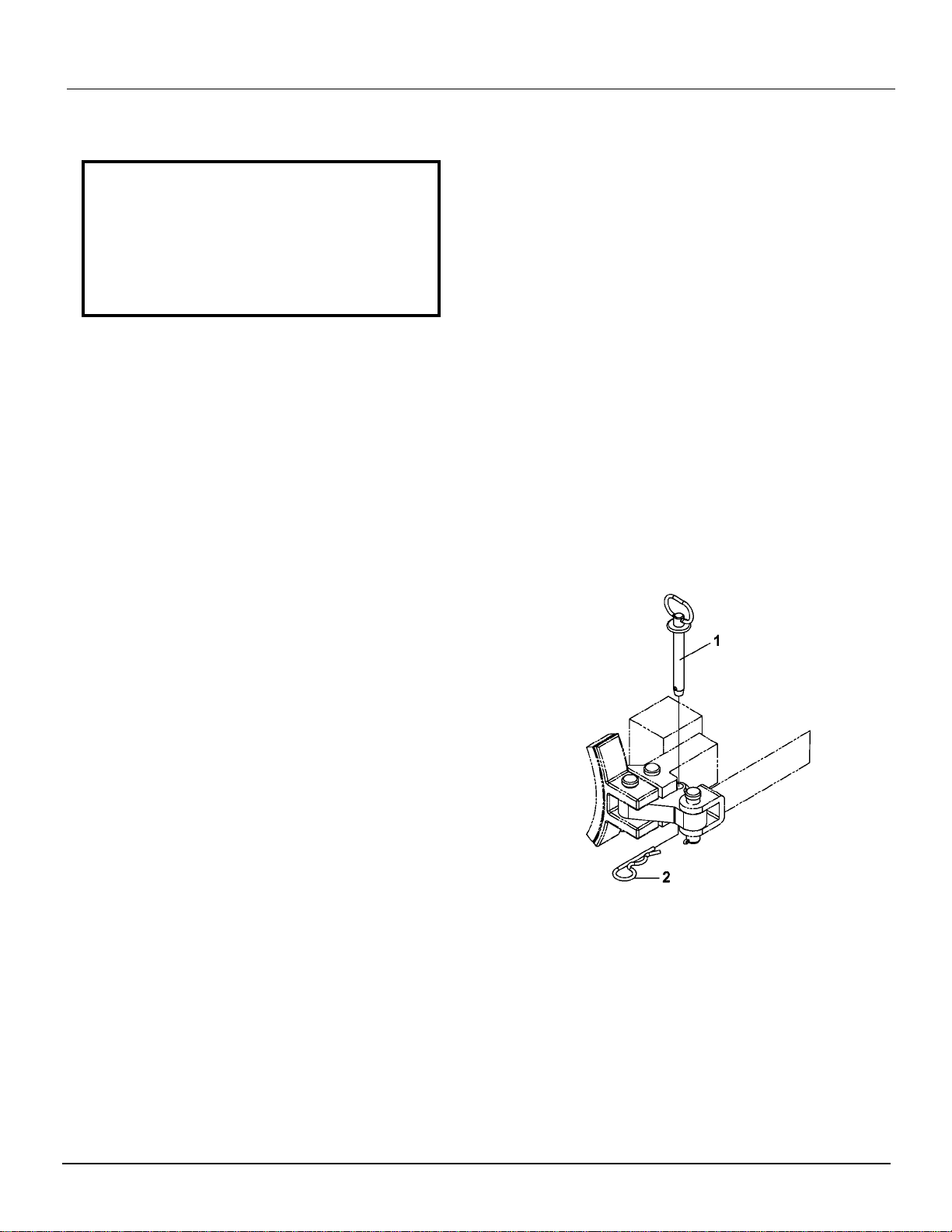
9. Turn on the emergency pump at the
control box until the hydraulic brake
cylinder has collapsed and has
released the brakes.
10. Install the lockpins (1) and hairpin
cotters (2) as shown in drawing to
right.
11. Turn off emergency pump, remove
hose and wheel chocks, and perform
towing as required.
12. Once you have towed to a site to
perform maintenance on the
hydraulic system, open the ball valve
(closed under step 7) and lock in the
OPEN position.
Tools And Equipment Required For These
Procedures:
¾-Inch Combination Wrench
Company Furnished Padlock
Pump Hose (Found In Toolbox)
Lockpins (Found In Toolbox)
HYDRAULIC Anchor Applicator Model BAAM
Section H-4 MAR/2005 (49454100)
EMERGENCY PUMP USE – MANUAL
PUMP
For All Components Except Brakes:
1. Turn ignition switch to the OFF
position.
2. Attach one end of the hose (found in
the toolbox) to hand pump and the
other end of the hose to the quick
disconnect at the brake lock valve.
3. Pressurize the hand pump by moving
the hand valve lever (lever with round
knob) on the pump toward the pump.
4. Continue pumping until all components
are raised to the point where you can
insert lockups. Insert lockup pins.
5. Continue on to lock off brakes for
towing.
For the Hydraulic Brakes:
8. With the machine on level track,
chock ALL wheels to prevent
movement.
9. Close the ball valve at the brake valve
stack (see photo to right) and lock in
the CLOSED position. (CLOSED is
perpendicular to the hose line, OPEN
is parallel to the hose line.)
10. Attach one end of the hose (found in
the toolbox) to the electric pump.
Attach the other end of the hose to
the quick disconnect at the brake
valve.
11. Turn on the emergency pump at the
control box.
12. Once the hydraulic brake cylinder has
collapsed and has released the
brakes, install the lockpins as shown.
13. Release hand pump pressure by
moving the hand valve lever on the
pump away from the pump, , remove
hose and wheel chocks, and perform
towing as required.
14. Once you have towed to a site to
perform maintenance on the hydraulic
system, open the ball valve (closed
under step 9) and lock in the OPEN
position.
Tools And Equipment Required For These
Procedures:
¾-Inch Combination Wrench
Company Furnished Padlock
Hand Pump Hose (Found In Toolbox)
Lockpins (Found In Toolbox)

Anchor Applicator Model BAAM HYDRAULIC
SEPT/2005 (49456900) Section H-5
HYDRAULIC PRESSURE SETTINGS
Main System Pressure: 2250 psi Main Relief Valve: 3000 psi
Crossover Relief: 2900 psi Guide Roller PRV: 600 psi
Tool Flip & Boxing PRV’s: 1000 psi Feed Grip PRV: 650 psi
Bulk Loader Kick Down Relief: 2000 psi

HYDRAULIC Anchor Applicator Model BAAM
Section H-6 MAR/2005 (49454100)
MAIN SYSTEM PRESSURE & RELIEF SETTINGS
Install the pressure gauge on the pressure tap for the main system pump
as shown in the picture at the left.
Turn relief valve adjustment screw to full clockwise (CW) position
(maximum pressure).
Turn pump compensator screw counterclockwise (CCW) (about 2-3
turns), but do not remove screw. Leave enough thread engagement to
prevent leakage. Start engine and turn on the Pump.
Turn pump compensator clockwise (CW)until 3000 psi has been
reached. Read this pressure at the main system gage on the propulsion
manifold.
Adjust relief counterclockwise (CCW) until pressure at gauge just begins
to drop. This is considered cracking pressure. Turn back 1/8 of a turn
and tighten locknut.
DO NOT ADJUST THE RELIEF VALVE FOR FULL FLOW PRESSURE!
Refer to next page to set Crossover Relief Valves.

Anchor Applicator Model BAAM HYDRAULIC
SEPT/2005 (49456900) Section H-7
CROSSOVER RELIEF SETTINGS
MAKE CERTAIN BRAKES ARE FULLY ENGAGED AND CAN HOLD
MACHINE STATIONARY BEFORE CONTINUING WITH THESE
ADJUSTMENTS. FAILURE TO DO SO MAY
CAUSE SEVERE BODILY HARM
With the pressure gauge on the pressure tap for the main system pump
still attached:
Turn both crossover relief valve adjustments screws to full clockwise
(CW) position (maximum pressure).
Back out compensator until system pressure reaches 2900 psi.
Manually override FWD relief valve.
Adjust valve counterclockwise (CCW) until pressure at gauge just begins
to drop. This is considered cracking pressure. Turn back 1/8 of a turn
and tighten locknut.
Manually override REV relief valve.
Adjust valve counterclockwise (CCW) until pressure at gauge just begins
to drop. This is considered cracking pressure. Turn back 1/8 of a turn
and tighten locknut.
Adjust pump compensator counterclockwise (CCW) to system operating
pressure (2500 psi).

HYDRAULIC Anchor Applicator Model BAAM
Section H-8 MAR/2005 (49454100)
TOOL FLIP PRESSURE REDUCING VALVE SETTINGS
Plug in gage at pressure port as shown in picture.
Turn on pump. Read pressure.
If pressure is higher than 1000 psi, loosen nut on spotting
valve adjusting screw and turn counterclockwise (CCW)
until pressure reads 1000 psi. Tighten nut at new
location.
If pressure is lower than 1000 psi, loosen nut on spotting
valve adjusting screw and turn clockwise (CW) until
pressure reads 1000 psi. Tighten nut at new location.

Anchor Applicator Model BAAM HYDRAULIC
SEPT/2005 (49456900) Section H-9
BOXING PRESSURE REDUCING VALVE SETTINGS
Plug in gage at pressure port as shown in picture.
Turn on pump. Read pressure.
If pressure is higher than 1000 psi, loosen nut on spotting
valve adjusting screw and turn counterclockwise (CCW)
until pressure reads 1000 psi. Tighten nut at new
location.
If pressure is lower than 1000 psi, loosen nut on spotting
valve adjusting screw and turn clockwise (CW) until
pressure reads 1000 psi. Tighten nut at new location.

HYDRAULIC Anchor Applicator Model BAAM
Section H-10 MAR/2005 (49454100)
BULK LOADER KICK-DOWN RELIEF VALVE SETTINGS
Plug in gage at pressure port as shown in picture.
Turn on pump. Read pressure.
If pressure is higher than 2000 psi, loosen nut on spotting
valve adjusting screw and turn counterclockwise (CCW)
until pressure reads 2000 psi. Tighten nut at new
location.
If pressure is lower than 2000 psi, loosen nut on spotting
valve adjusting screw and turn clockwise (CW) until
pressure reads 2000 psi. Tighten nut at new location.

Anchor Applicator Model BAAM HYDRAULIC
SEPT/2005 (49456900) Section H-11
GUIDE ROLLER PRESSURE REDUCING VALVE SETTING
Plug in gage as shown in picture.
Turn on pump. Read pressure.
If pressure is higher than 600 psi, loosen nut on spotting
valve adjusting screw and turn counterclockwise (CCW)
until pressure reads 600 psi. Tighten nut at new location.
If pressure is lower than 600 psi, loosen nut on spotting
valve adjusting screw and turn clockwise (CW) until
pressure reads 600 psi. Tighten nut at new location.

HYDRAULIC Anchor Applicator Model BAAM
Section H-12 MAR/2005 (49454100)
FEED GRIP PRESSURE REDUCING VALVE SETTING
Plug in gage in RH or LH port as shown in picture. (Attach
gage to valve stack being adjusted.)
Turn on pump. Read pressure.
If pressure is higher than 650 psi, loosen nut on spotting
valve adjusting screw and turn counterclockwise (CCW)
until pressure reads 650 psi. Tighten nut at new location.
If pressure is lower than 650 psi, loosen nut on spotting
valve adjusting screw and turn clockwise (CW) until
pressure reads 650 psi. Tighten nut at new location.
Repeat for other side.

Anchor Applicator Model BAAM HYDRAULIC
SEPT/2005 (49456900) Section H-13
RETURNING HYDRAULICS TO FACTORY SETTINGS
(To be used in the event that valves were incorrectly set)
VALVE HOW TO ADJUST
Workhead Lift
Counterbalance Valve With the WORKHEAD LIFT lock-up rocker switch unlocked, set the
counter-balance valve on WORKHEAD LIFT (bottom valve in
stack) by turning the adjusting screw CCW and stopping just before
the workhead starts to drift down (approximately 2-1/2 turns CCW
from closed). The Workhead is not to drift down when the machine
is shut down.
Workhead Lift
Flow Control Valve Remove the slow speed valve DIN connector and set WORKHEAD
LIFT flow control (2nd valve from bottom) such that the travel time to
fully retract the lift cylinder from its extended length is approximately
1 second (approximately 7 turns CCW from closed).
Workhead Lift
Slow Speed Valve Re-install the slow speed valve DIN connector and set the
WORKHEAD LIFT slow speed valve (3rd valve from the bottom)
such that the travel time to extend the lift cylinder 1” is
approximately 1 second (approximately ¾ turn from closed).

HYDRAULIC Anchor Applicator Model BAAM
Section H-14 MAR/2005 (49454100)
RETURNING HYDRAULICS TO FACTORY SETTINGS
(To be used in the event that valves were incorrectly set)
VALVE HOW TO ADJUST
Workhead Rotate
Counterbalance Valve With the WORKHEAD ROTATE lock-up rocker switch unlocked,
set the counter-balance valve on WORKHEAD ROTATE (bottom
valve in stack) by turning the adjusting screw CCW and stopping
just before the workhead starts to drift down (approximately 1-1/2
turns CCW from closed). The workhead is not to drift down when
the machine is shut down.
Workhead Rotate
Flow Control Valve Set WORKHEAD ROTATE flow control (2nd valve from bottom)
such that the travel time to fully retract the rotate cylinders is
approximately ½ second (approximately 7 turns CCW from closed).

Anchor Applicator Model BAAM HYDRAULIC
SEPT/2005 (49456900) Section H-15
TROUBLESHOOTING - GENERAL
Troubleshooting is a matter of quickly and logically isolating the cause of a problem and taking
corrective action. Operating experience, a thorough understanding of the information in this manual,
and accurate maintenance and operation records are the best troubleshooting tools an operator can
have.
This is intended to give you basic troubleshooting guidelines for the hydraulic systems on this machine.
Local conditions and operating methods may result in problems, causes and remedies not covered in
this guide. To use the guide most efficiently, locate a problem that matches the one being experience
and, in a step-by-step method, check the causes listed until the correct remedy is found and the
problem solved.
Always turn off machine when performing maintenance, making adjustments, or whenever
unintended movement of machine could occur; unless directed otherwise. Failure to comply
could result in personal injury and/or damage to the machine.
To avoid possible personal injury and/or engine damage from accidental engine startup, always
disconnect the battery before servicing this machine.
INSPECTION
Inspect the hydraulic system for clues to the malfunction. Check to see if the unit can be operated
without further damage. If not, shut down machine immediately. Always check these items before
starting the machine:
1. Check hydraulic oil level.
2. Look for loose or disconnected hoses. An oil spot below the machine is a good indication of a
loose hose or hydraulic component.
3. Make certain shut-off valve on suction strainer is OPEN. Opening valve can often correct what
appears to be a malfunction.
4. Inspect all vital hose connections, especially at main pump and the main pump hose
connection at the manifold.
Loosen fittings only when system is not pressurized. High pressure leaks can cause personal
injury.
5. Look for cover damage and/or indications of twisted, worn, crimped, brittle, cracked, or leaking
hoses. Hoses with their outer cover worn through or otherwise damages should be considered
unfit for further service.

HYDRAULIC Anchor Applicator Model BAAM
Section H-16 MAR/2005 (49454100)
While machine is running, and before working, inspect for leaks. If the machine has not been run for
some time, oil may thicken causing a variety of malfunctions. If this is true, make certain that the oil
tank has been properly drained, cleaned and refilled.
If your visual inspection does not indicate the possible malfunction, refer to the troubleshooting guide
that follows.
FLUID CONTAMINATION
Contamination comes in many forms. It may be air, water and cutting oils, rust, chips and grit. It is
usually easier to keep contaminants out of a system rather than remove them after they are in the
system.
Bulk handling and the re-use of oil containers almost guarantees you that "new" oil will be dirty. Make it
a practice to filter all "new" oil before adding it to your system. Make it another practice to change
filters on a regular basis before they become clogged.
LOCATING LEAK SOURCES
Petroleum oils are used in most hydraulic application to lubricate parts as well as transmit power. As
oil temperature increases, however, the lubricating film thins out. The result is rubbing parts supported
by the oil film move closer together; friction and wear increase; seal materials age more quickly,
become stiff and hard, and may readily permit leakage.
The first step in locating leaks is to eliminate the possibility that an over-filled reservoir or spill created
the "suspected" leak. The next step would be to clean the suspected area and watch. Leaks usually
occur in fittings, hoses, O-rings, and other seals.
Most leaks occur at fittings, but too often, finding the fitting that is leaking is difficult because the fluid
runs along the hose and drips off at some other point. Leaks in high pressure lines sometimes are
difficult to pin-point because the fluid comes out as a mist.
Once you find the location of a leak, the specific cause has to tbe determined before it can be
corrected. A scratch in a fitting seat or a cut in a seal lip that is big enough to leak excessively can still
be too small to find with the naked eye. The use of a magnifying glass would assist you.
HOSE LIFE
Hose leakage or failure many times occurs where the end fitting grips the hose. Check the system for
pressure spikes or surge. If bulges or bubbles occur on a flexible hose, a leak is taking place within the
layers. The hose should be replaced.
High oil temperatures (over 200 degrees Fahrenheit, 93 degrees Celcius) quickly harden or stiffen a
rubber hose. When pressure pulses flex a hardened hose, it fails by cracking. Every increase of 25°F
(14°C) cuts hose life in half. Use a replacement hose rated for actual fluid temperatures. Keep a log of
hose use so replacement can be made before failure occurs.
If a hose is installed with a twist in it, high operating pressures tend to force it straight. This can loosen
the fitting or even burst the hose at the point of the strain.

Anchor Applicator Model BAAM HYDRAULIC
SEPT/2005 (49456900) Section H-17
HYDRAULIC SYSTEM
TROUBLESHOOTING GUIDE
PROBLEM
POSSIBLE CAUSE
SOLUTION
Hydraulic pump does
not develop pressure
No hydraulic oil in tank (NOTE: if pump is
run without oil in tank, pump damage will
occur.)
Shut-off valve closed. (NOTE: if pump is
run with valve closed, pump damage will
occur.)
Main relief valve bypassing. (NOTE: oil
blowing past any relief valve can cause
oil to overheat.)
Main pump compensator setting is too
low.
Pump is defective.
Destroke valve stuck.
Pump switch turned off.
Check oil level. Refill tank.
Open valve completely.
Increase pressure setting on
relief valve. (See Pressure
checks)
Adjust compensator setting.
(See Pressure Checks)
Refer to pump manual or
replace pump.
Repair or replace.
Turn on.
Hydraulic pump
excessively noisy
Cold oil.
Low oil level.
Oil viscosity too high (oil too thick)
System relief valve set too low.
Intake hose to pump restricted.
Defective pump.
Allow unit to warm up.
Check and add oil.
Drain and add correct oil as
specified under
"RECOMMENDED
LUBRICANTS".
Increase pressure setting on
relief valve (see Pressure
Checks)
Inspect and repair.
See pump manual, repair or
replace pump.
Machine will not propel
Main pump not developing pressure.
Propulsion relief setting too low.
Nippers not retracted or nipper work up
switch not actuated.
See above.
Increase relief setting. (See
Pressure checks)
Check nipper up switch, repair
or replace.
Hydraulic Oil
Overheats
Oil viscosity too high (oil too thick)
System relief valve set too low.
Drain and add correct oil as
specified under
"RECOMMENDED
LUBRICANTS".
Increase pressure setting on
relief valve
(
see Pressure

HYDRAULIC Anchor Applicator Model BAAM
Section H-18 MAR/2005 (49454100)
PROBLEM
POSSIBLE CAUSE
SOLUTION
Oil lines damaged causing excessive
internal restriction
Travel relief set too low
Checks)
Inspect and repair.
Check and reset
Hydraulic Oil Foams
Water in oil
Using wrong oil
Low hydraulic level
Damaged hydraulic oil lines
Air leak in suction line to hydraulic pump
or pump shaft seal leaking
Inspect oil for water. Drain and
add correct oil as specified
under "RECOMMENDED
LUBRICANTS".
Drain and add correct oil as
specified under
"RECOMMENDED
LUBRICANTS".
Fill
Inspect, repair or replace.
Inspect, repair or replace.
Hydraulic Oil Filter
Restriction Indicator
Light stays on all the
time (optional
equipment)
Restricted hydraulic oil filter.
Hydraulic oil filter restriction switch
Replace filter.
Replace switch.
Table of contents
Other Nordco Tools manuals

Popular Tools manuals by other brands


SKF
SKF TMBS 100E Instructions for use

Cornwell Tools
Cornwell Tools CTGCSGGA Operating instructions, warning information, parts breakdown

Rosenberger
Rosenberger 60W107-CX5 Instruction

NovoPress
NovoPress ACO203 operating manual

HAUL MASTER
HAUL MASTER 30131 Owner's manual & safety instructions

Simpson
Simpson PTP-27ASMAGR Operator's manual