Nordic ID AR82 User manual
2018-04-09
Nordic ID AR82 User Guide
Version 1.2
NORDIC ID AR82
USER GUIDE
Nordic ID Group | Joensuunkatu | FI-24100 Salo |Finland
2 / 20
2018-04-09
Nordic ID AR82 User Guide
Version 1.2
TABLE OF CONTENTS
GETTING STARTED ............................................................................................................................................................ 4
1.1.
GENERAL ............................................................................................................................................................. 4
1.2.
AVAILABLE VARIANTS .................................................................................................................................... 4
1.3.
AVAILABLE ACCESSORIES ............................................................................................................................. 4
1.4.
PACKAGE CONTENT ....................................................................................................................................... 4
1.5.
FEATURES AND CONNECTORS OVERVIEW ............................................................................................ 5
1.6.
MOUNTING ........................................................................................................................................................
1. .
POWERING THE READER ...............................................................................................................................
1.8.
PHYSICAL CONNECTORS .............................................................................................................................. 8
DC CONNECTOR ............................................................................................................................... 8
GPIO CONNECTOR ........................................................................................................................... 8
ANTENNA PORTS ........................................................................................................................... 10
USB 2.0 DEVICE WITH TYPE B CONNECTOR ......................................................................... 10
USB 2.0 HOST WITH TYPE A CONNECTOR ............................................................................ 11
ETHERNET ........................................................................................................................................ 11
DUAL BAND WLAN (OPTIONAL) ................................................................................................ 11
WWAN CELLULAR CONNECTIVITY (OPTIONAL) .................................................................. 11
SLOT FOR MINI SIM CARD (OPTIONAL) .................................................................................. 11
1.9.
USER INTERFACE ........................................................................................................................................... 12
LED INDICATORS ............................................................................................................................ 12
1.9.1.1.
POWER LED .................................................................................................................................. 12
1.9.1.2.
CONNECTION LED...................................................................................................................... 12
1.9.1.3.
RFID LED ........................................................................................................................................ 13
1.9.1.4.
INDICATION LED ......................................................................................................................... 13
RESET BUTTON ............................................................................................................................... 13
1.10.
RF PROFILES ................................................................................................................................................ 14
1.11.
THERMAL MANAGEMENT ...................................................................................................................... 14
SOFTWARE ....................................................................................................................................................................... 16
2.1.
NORDIC ID RFID APPLICATIONS FOR NORDIC ID AR82 ................................................................... 16
NORDIC ID RFID DEMO ................................................................................................................ 16
NORDIC ID RFID CONFIGURATOR ............................................................................................ 16
NORDIC ID APPLICATION SIGNING TOOL ............................................................................. 16
WEB MANAGEMENT INTERFACE .............................................................................................................................. 16
REGIONAL SETTINGS ..................................................................................................................................................... 1
SERVICE AND SUPPORT................................................................................................................................................ 1
WARRANTY ....................................................................................................................................................................... 1
RELATED DOCUMENTS AND CONTENT ................................................................................................................. 1

Nordic ID Group | Joensuunkatu | FI-24100 Salo |Finland
3 / 20
2018-04-09
Nordic ID AR82 User Guide
Version 1.2
ABOUT NORDIC ID ......................................................................................................................................................... 18
VERSION HISTORY .......................................................................................................................................................... 18
APPENDICES ..................................................................................................................................................................... 19
10.1.
EXAMPLE SCHEMATICS OF GPIO INTERFACE ................................................................................. 19

Nordic ID Group | Joensuunkatu | FI-24100 Salo |Finland
4 / 20
2018-04-09
Nordic ID AR82 User Guide
Version 1.2
GETTING STARTED
1.1. GENERAL
Nordic ID AR82 is a fixed 16 port reader with a computer inside and multiple connectivity options.
Nordic ID AR82 provides powerful UHF RFID performance with highly isolated external antenna ports
that prevents cross readings. This makes Nordic ID AR82 ideal for shelf reading. Nordic ID NUR2-1W
module inside allows reading speed of up to 1000 tags/s. It’s integrated computer enables installation and
operation of 3rd party applications.
1.2. AVAILABLE VARIANTS
Nordic ID AR82 is available in 3 different variants:
CODE DESCRIPTION
NPF00003 Nordic ID AR82 / UHF RFID (USB / LAN 10 /100&PoE)
NPF00004 Nordic ID AR82 / UHF RFID (USB / LAN 10 /100&PoE / WLAN)
NPF00005 Nordic ID AR82/ UHF RFID (USB / LAN 10 /100&PoE / WLAN / WWAN (3G))
1.3. AVAILABLE ACCESSORIES
CODE DESCRIPTION
ACN00141 Nordic ID USB cable (Length 1.8m, type B male – type A male -connectors)
ACN00142 Nordic ID Power supply 100-240 VAC, 50-60 Hz / 24 VDC for Nordic ID AR and
Sampo S2 readers, EU (Includes power supply and cable)
ACN00143 Nordic ID Power supply 100-240 VAC, 50-60 Hz / 24 VDC for Nordic ID AR and
Sampo S2 readers, UK (Includes power supply and cable)
ACN00145 Nordic ID Power supply 100-240 VAC, 50-60 Hz / 24 VDC for Nordic ID AR and
Sampo S2 readers, US (Includes power supply and cable)
CWH00045 Nordic ID External antenna cable (Length 1m, SMA-male -connectors)
CWH00020 Nordic ID External antenna cable (Length 3m, SMA-male -connectors)
CWH00019 Nordic ID External antenna cable (Length 5m, SMA-male -connectors)
CWH00042 Nordic ID External antenna cable (Length 10m, SMA-male -connectors)
1.4. PACKAGE CONTENT
Nordic ID AR82 package contains following items
•Nordic ID AR82
•VESA 5 compatible mounting bracket

Nordic ID Group | Joensuunkatu | FI-24100 Salo |Finland
5 / 20
2018-04-09
Nordic ID AR82 User Guide
Version 1.2
•Installation kit
•Safety and regulations guide
1.5. FEATURES AND CONNECTORS OVERVIEW
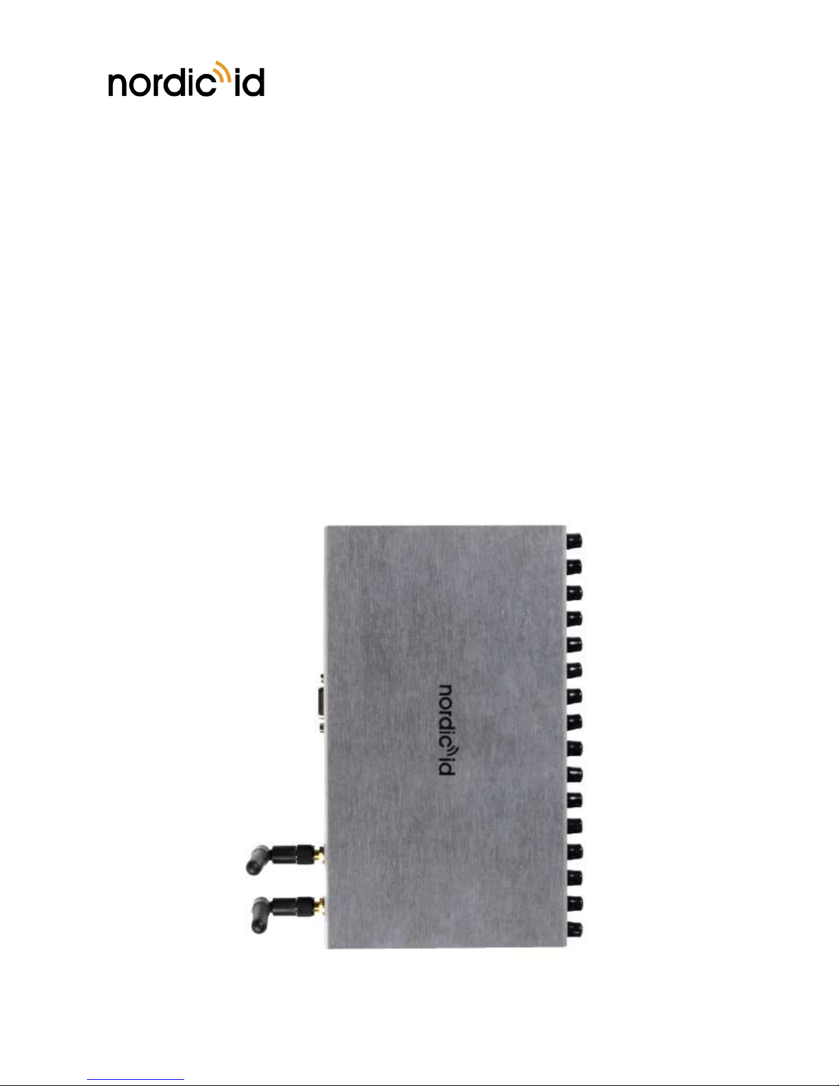
WLAN and WWAN (3G) variants of Nordic ID AR82 UHF RFID include external WLAN and WWAN
antennas that needs to be fastened to the reader before it’s taken into use.
Picture 1 Rear panel of Nordic ID AR82
Picture 2 Rear panel of Nordic ID AR82
NOTE! Power supply not included

Nordic ID Group | Joensuunkatu | FI-24100 Salo |Finland
6 / 20
2018-04-09
Nordic ID AR82 User Guide
Version 1.2
Picture 3 ront panel of Nordic ID AR82

Nordic ID Group | Joensuunkatu | FI-24100 Salo |Finland
/ 20
2018-04-09
Nordic ID AR82 User Guide
Version 1.2
1.6. MOUNTING
Nordic ID AR82 can be mounted using VESA 5 compatible mounting bracket (included in sales package).
Picture 4 Inserting Nordic ID AR82 to VESA 75 compatible mounting bracket
1. . POWERING THE READER
Nordic ID AR82 can be powered via DC power supply (sold separately) or ethernet port if the network
supports power over Ethernet (PoE) feature or PoE injector is being used. Regardless of what powering
method is used, the data communication can be handled via USB connection or if IP connectivity is
required then via WWAN, WLAN or ethernet. Nordic ID AR82 powers up automatically when connected
to DC power supply or PoE.
The rated maximum power consumptions for Nordic ID AR82 reader are:
• Powered via 802.3af PoE: 12W
• Powered via DC power supply (sold separately): 20W (12-24V DC)

Nordic ID Group | Joensuunkatu | FI-24100 Salo |Finland
8 / 20
2018-04-09
Nordic ID AR82 User Guide
Version 1.2
1.8. PHYSICAL CONNECTORS
Nordic ID AR82 includes the following physical connectors:
•DC connector for supplying power if PoE capability is not used (power supply sold separately)
•GPIO connector (4 optically isolated inputs and outputs)
•16 pcs SMA female antenna connectors for connecting external antennas to the reader
•USB 2.0 device Type B connector (USB HID profile supported)
•USB 2.0 host Type A connector
•Ethernet 10/100Mbps with 802.3af support
•Dual band WLAN (optional)
•WWAN cellular connectivity (optional)
•Slot for mini SIM card (optional)
DC CONNECTOR
DC connector is used to power up the reader using Nordic ID provided power supplies. More information
about the Nordic ID power supplies can found from table 1.3. Supported input voltage is 12 – 24V DC.
GPIO CONNECTOR
Nordic ID AR82 includes a multipurpose GPIO connector that contains the following functionalities:
•RS-232 serial port
•4 x opto-isolated inputs
•4 x opto-isolated outputs
•+5VDC supply
•12VDC / 24 VDC supply
12VDC if the reader is powered via PoE and 24VDC if the reader is powered via external power supply.
The multipurpose GPIO connector can be accessed via DE15 connector located on rear panel of the
NOTE! WLAN and 3G are disabled If the reader is powered via the PoE. 802.3af PoE can’t
provide enough power to the reader to keep WLAN and 3G features working as expected.

Nordic ID Group | Joensuunkatu | FI-24100 Salo |Finland
9 / 20
2018-04-09
Nordic ID AR82 User Guide
Version 1.2
reader. Pin-out of the DE15 connector can be seen in Figure 1. Functions and electrical specification of
the GPIO connector can be found from
Table 1 and Table 2.
igure 1 Pin-out of DE15 connector
Table 1 Signal of GPIO connector
PIN SIGNAL NAME DESCRIPTION
1 5V output 5V DC output, switchable on/off
2 RS232 TX RS232 output
3 RS232 RX RS232 input
4 Ground Ground
5 Output 0 Isolated output 0
6 Output 1 Isolated output 1
Output 2 Isolated output 2
8 Output 3 Isolated output 3
9 V- Isolated ground for inputs and outputs
10 Input 0 Isolated input 0
11 Input 1 Isolated input 1
12 Input 2 Isolated input 2
13 Input 3 Isolated input 3
14 V+ Pull-up voltage for outputs, 10kΩ pull up resistors

Nordic ID Group | Joensuunkatu | FI-24100 Salo |Finland
10 / 20
2018-04-09
Nordic ID AR82 User Guide
Version 1.2
15 12V / 24V output 12V out with POE powered and 24V out with external power supply
Table 2 Electrical specifications of the signals
SIGNAL NAME
VOLTAGE
MIN (V)
VOLTAGE
NOMINAL (V)
VOLTAGE
MAX (V)
CONDITIONS
5V out 5 <200mA
RS232 TX, high 5 5,4 3KΩ load to Ground
RS232 TX, low -5,4 -5 3KΩ load to Ground
RS232 RX, high 2,4 25
RS232 RX, low -25 0,6
Ground 0
Outputs 0 - 3, high 30 10KΩ pull up to V+
Outputs 0 - 3, low 0 0,6 max 25mA, max 150mW
V- 0
Inputs 0 - 3, high 3 30 Between V+ and V-, max
6mA at 30V
Inputs 0 - 3, low 0 0, Between V+ and V-
V+ 30 Between V+ and V-
12V / 24V output 12 / 24 <200mA
Example schematics about how to create non-isolated and isolated solutions can be found from section
10.1.
ANTENNA PORTS
Nordic ID AR82 includes 16pcs SMA female antenna connectors for connecting external antennas to the
reader. Impedance of antenna ports is 50Ω and maximum radiated output power is 30dBm. The antenna
ports can be configured independently via NUR API.
USB 2.0 DEVICE WITH TYPE B CONNECTOR
Nordic ID AR82 includes USB 2.0 device Type B connector for connecting reader to host device. Nordic
ID AR82 supports also USB HID class which means the reader can act as a standard USB input device for
host devices.
NOTE! If 5V or 12V / 24V output is used, connect pins 4 and 9 together.

Nordic ID Group | Joensuunkatu | FI-24100 Salo |Finland
11 / 20
2018-04-09
Nordic ID AR82 User Guide
Version 1.2
USB 2.0 HOST WITH TYPE A CONNECTOR
Nordic ID AR82 includes USB 2.0 host Type A connector for connecting peripheral USB devices to the
reader. The USB 2.0 host Type A connector can be used to connect needed USB peripherals to the reader
to expand its functionalities. Maximum current out from the USB 2.0 host Type a connector is 500mA.
ETHERNET
Nordic ID AR82 includes standard RJ-45 ethernet connector. The reader supports 10/100Mbps speed
class and 802.3af PoE.
DUAL BAND WLAN (OPTIONAL)
Certain variants of Nordic ID AR82 include dual band WLAN supporting 2.4GHz and 5.0GHz frequency
bands. External dual band WLAN antenna needs to be attached to the reader to make WLAN perform
and work as specified. Nordic ID AR82 can work as a WLAN access point to other WLAN devices thus
enabling simple and cost-efficient network of several readers and devices.
WWAN CELLULAR CONNECTIVITY (OPTIONAL)
Certain variants of Nordic ID AR82 include WWAN connectivity supporting 2G and 3G cellular networks.
External WWAN antenna needs to be attached to the reader to make WWAN perform and work as
specified. WWAN connectivity needs a SIM card to be functional. Please find more information about
how the SIM card is inserted to the Nordic ID AR82 from section 1.8.9.
SLOT FOR MINI SIM CARD (OPTIONAL)
The WWAN variant of Nordic ID AR82 includes a slot for mini SIM card. Mini SIM card is to be inserted
in the slot in a right orientation to be functional. The correct insertion orientation of mini SIM card can be
seen from the Picture 5.
Picture 5 Insertion orientation of mini SIM card
NOTE! Web management interface can’t be access using USB connector. Web management
interface can be accessed only using ethernet, WLAN and WWAN connections.
Nordic ID Group | Joensuunkatu | FI-24100 Salo |Finland
12 / 20
2018-04-09
Nordic ID AR82 User Guide
Version 1.2
1.9. USER INTERFACE
User interface of Nordic ID AR82 consists of 4 LED indicators and a reset button on the back of the
reader.
LED INDICATORS
Nordic ID AR82 has four programmable LEDs for user indications. Location of the LEDs can be seen in
Picture 6. It’s possible to enable/disable all the LEDs via web management UI and/or reader API. By
default the LEDs are enabled. LEDs of the reader are:
1. Power LED
2. Connection LED
3. RFID LED
4. Indication LED
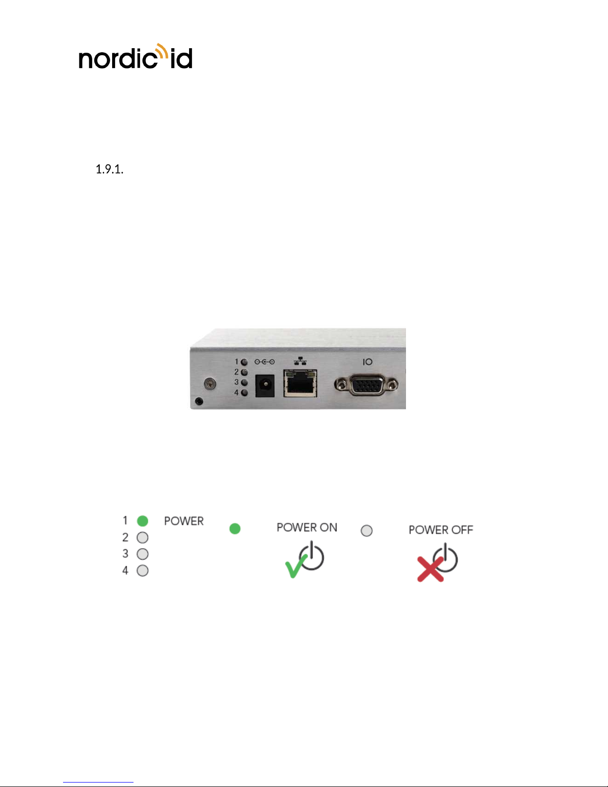
Picture 6 Location of LEDs
1.9.1.1. POWER LED
By default, Power LED indicates if the power is supplied to the device via DC power supply or PoE.
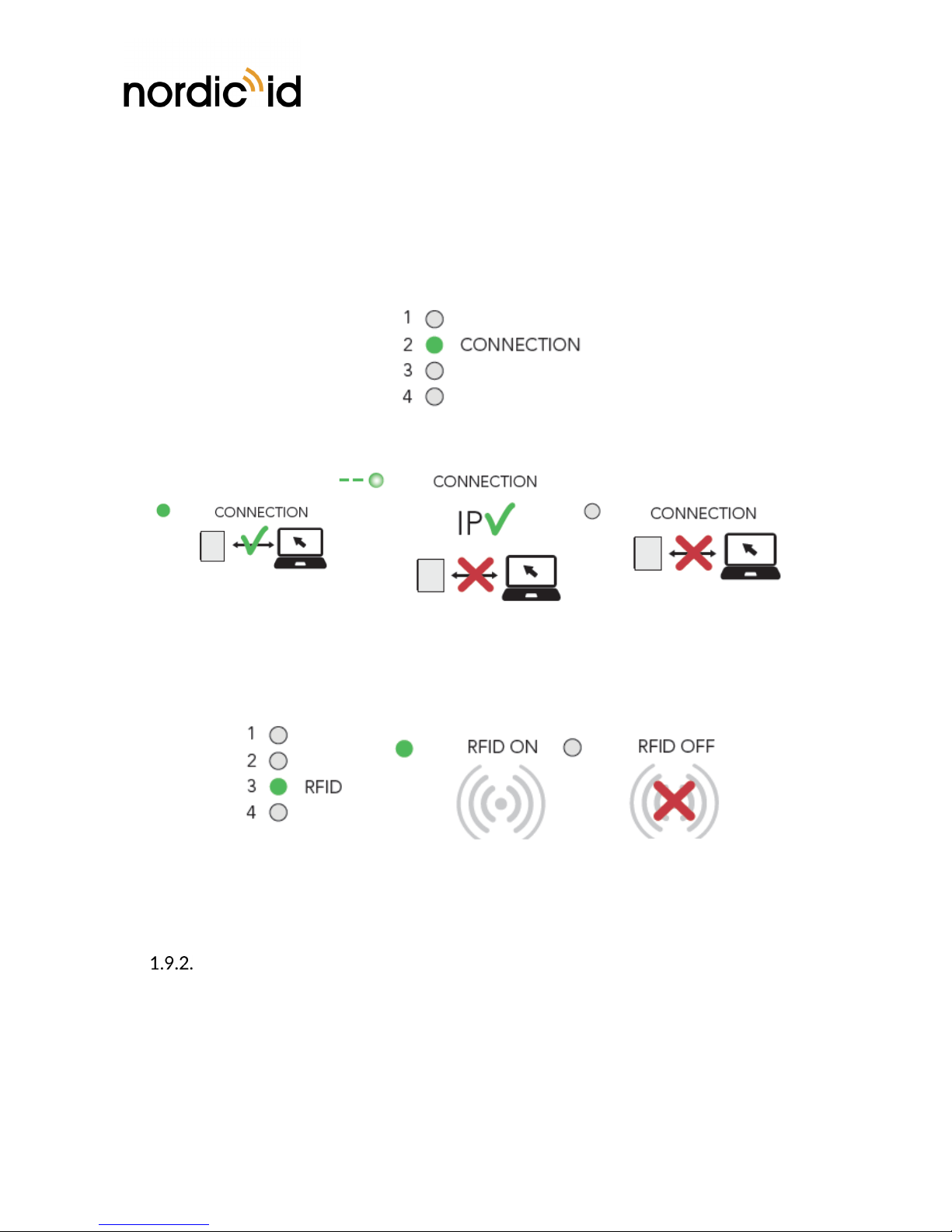
1.9.1.2. CONNECTION LED
Connection LED indicates whether the reader has established USB, ethernet, WLAN or WWAN
connection. Functionality of the Connection LED can be configured via NUR API if needed. Functionality
of the Connection LED differs depending on whether USB or TCP/IP (ethernet, WLAN and WWAN)
connection is used.
•USB connection in use
oLED off: The USB cable is unplugged.
Nordic ID Group | Joensuunkatu | FI-24100 Salo |Finland
13 / 20
2018-04-09
Nordic ID AR82 User Guide
Version 1.2
oLED on: The USB cable is connected.
•Ethernet, WLAN or WWAN connection in use
oLED off: The reader has no IP address.
oLED blinking: The reader has IP address, but the client application is not connected.
oLED on: The reader has IP address and the client application is connected.
1.9.1.3. RFID LED
RFID LED indicates whether the RFID reading is ON or OFF. Functionality of the RFID LED can be
configured via NUR API if needed.
1.9.1.4. INDICATION LED
Indication LED is used to indicate different reset states. See section 1.9.2 for more information.
RESET BUTTON
Reset button of Nordic ID AR82 contains the following functionalities:
•Rebooting the reader
oPress the reset button 2s (red INDICATION LED starts blinking once the reset button is
pressed) and release it once 3 green LEDs are turned on.
•Boot to recovery mode*

Nordic ID Group | Joensuunkatu | FI-24100 Salo |Finland
14 / 20
2018-04-09
Nordic ID AR82 User Guide
Version 1.2
oIf reset button is not released, green CONNECTION and RFID LEDs turn off and green
Power LED is on. INDICATION LED starts blinking in red. After a while green RFID LED
is turned on.
oRelease the reset button when the RFID LED has turned on to enter to the recovery
mode. This mode can be entered within 5s after the RFID LED has been turned on.
•Factory reset
oIf reset button is not released red INDICATION LED starts blinking even faster and green
CONNECTION LED is turned on
oRelease the reset button when the CONNECTION LED has turned on to enter to the
factory reset mode. This mode can be entered within 5s after the CONNECTION LED
has turned on.
* Recovery mode can be used to repair the reader
1.10. RF PROFILES
Nordic ID NUR2-1W UHF RFID module supports three different kind of RF profiles. The profiles are
Robust, Nominal and High speed. It’s important to select the correct RF profile based on use case and
environment. More detailed description about the RF profiles can be found below:
•Robust
oRobust RF profile is intended to be used in challenging environments. It provides the best
filtering against the interfering signals coming from nearby reader(s), other signal sources
and from reflective environment. This profile uses link frequency of 250 kHz and Miller
4 coding scheme providing read rates up to 200 tags/s. Due to the low data speed and
best filtering the Robust RF profile provides the best sensitivity.
•Nominal
oNominal RF-profile is the default setting of readers containing Nordic ID NUR2-1W UHF
RFID module. It uses link frequency of 300 kHz and Miller 2 coding providing read rates
up to 350 tags/s.
•High speed
oHigh speed RF profile is intended to be used in use cases where the highest read rates
are required. It uses link frequency of 400 kHz and FM0 coding and provides read rates
up to 1000 tags/s. Due to the high data speed the profile is quite sensitive to
interferences.
1.11. THERMAL MANAGEMENT
NOTE! If reset button is pressed over 5s after the CONNECTION LED has turned on and the red
INDICATION LED has started blinking even faster, releasing the reset button will perform a
normal reboot.
NOTE! Read rates will depend from the environment, reader settings, tag population and tag type.

Nordic ID Group | Joensuunkatu | FI-24100 Salo |Finland
15 / 20
2018-04-09
Nordic ID AR82 User Guide
Version 1.2
Nordic ID AR82 reader includes sophisticated thermal management features that do prevent overheating
issues if reader is used in too warm environments. The reader monitors temperatures of onboard
computer and UHF RFID module and adjusts operation points based on the temperature information.
Onboard computer starts mitigation scheme (for example clock frequencies of CPUs are dropped) when
temperature of the onboard computer reaches 85°C.
Thermal mitigation scheme of the UHF RFID module follows following temperatures:
•80°C – UHF RFID reading operations are suspended for 100ms. Suspend time is increased 20ms
by every °C temperature rises until the temperature reaches 90°C. The thermal mitigation
scheme is turned off once the temperature drops below 80°C. High temperature warning
message (TEMP_HIGH) is sent via NUR API to host. The warning message contains also current
temperature information.
•90°C – UHF RFID reading operations are shut down until temperature goes below 90°C. Once
the temperature is below 90°C, above mentioned mitigation scheme is taken in use. Over
temperature warning message (TEMP_OVER) is sent via NUR API to host. The warning message
contains current temperature information.

Nordic ID Group | Joensuunkatu | FI-24100 Salo |Finland
16 / 20
2018-04-09
Nordic ID AR82 User Guide
Version 1.2
SOFTWARE
All documentation about SW, SW features and application development can be find from GitHub.
https://github.com/NordicID/ar8x_samples
2.1. NORDIC ID RFID APPLICATIONS FOR NORDIC ID AR82
Nordic ID provides following Windows tools to test and configure the reader. The tools are available via
Nordic ID Support pages:
http://www.nordicid.com/en/downloads/
NORDIC ID RFID DEMO
Nordic ID RFID Demo application is for conducting the reading tests. It allows connecting the devices and
commencing the reading procedure. The application provides statistics on the reading performance and
logging capabilities for more thorough evaluation. As the Nordic ID RFID Configurator, this application
also allows adjusting the RFID parameters on the fly for better understanding how they impact on the
reading performance. The difference however is that altered settings cannot be stored permanently into
the device. The settings are reverted to defaults upon power cycle.
NORDIC ID RFID CONFIGURATOR
Nordic ID RFID Configurator is meant for configuring the reader settings. The settings can be e.g. related
to network settings or RFID reading parameters and stored into the device as new defaults. Note that
e.g. the RFID reading parameters can be assigned to the reader by the host application after successfully
connected to the device also. The RFID Configurator is also the tool for updating the device firmware if
seen necessary.
NORDIC ID APPLICATION SIGNING TOOL
To provide more security to the SW platform, the application zip-files need to be signed with Nordic ID
provided signing tool. The public key generated to the zip-file will be then verified against the list of files
when installing the zip-file to the reader. This makes sure that only valid content from the zip-file can be
installed.
The tool in question is called Nordic ID Application Signing Tool. The tool can be used to sign pre-built
zip-files, as also to create new zip-files from scratch.
WEB MANAGEMENT INTERFACE
Nordic ID AR82 includes a web management interface which can be accessed with a web browser. The
web management interface is used to configure the reader and manage applications. Documentation
about web management interface can be find from GitHub.
https://github.com/NordicID/ar8x_samples
NOTE! Web management interface cannot be accessed using USB connectors. Web management
interface can be accessed only using ethernet, WLAN and WWAN connections.

Nordic ID Group | Joensuunkatu | FI-24100 Salo |Finland
1 / 20
2018-04-09
Nordic ID AR82 User Guide
Version 1.2
REGIONAL SETTINGS
Nordic ID UHF RFID readers support operating frequency range between 860 - 960MHz. Some of the
readers cover full operating frequency band and some of them have two sub bands that are 868 ETSI
band (865.6 - 86 .6 MHz) and 915 FCC band (902 - 928 MHz). Regional organizations as ETSI and FCC
have set rules and requirements for operating frequencies, output power and other RF parameters for
the UHF RFID readers to comply local regional requirements.
Nordic ID has created a set of regional settings in order to fulfil local regulations. Nordic ID is required to
ensure that compliance of Nordic ID products will remain after production. Solution for this is that
products including UHF RFID functionality are set and locked in production based on customer order e.g.
if a product is ordered to Europe, it will be locked to ETSI region. And, if a product is ordered to Australia
region, it is locked to Australia region. When a product is locked to individual region, it will comply local
regulations of the region.
SERVICE AND SUPPORT
For technical enquiries regarding Nordic ID devices or software development, please contact our
Technical Support:
E-mail: support@nordicid.com
Telephone: +358 2 2 90
As a manufacturer, Nordic ID stands responsible for providing repair services for its devices during and
after the warranty period. Together with partners Nordic ID serves customers globally. When your Nordic
ID device needs repair, always use Nordic ID Service or our authorized service partners. We want to make
sure that your Nordic ID product serves you the best possible way, and by using our preferred service
partners the quality of the service is trustworthy and the spare parts are original. This way the existing
product warranty remains, and you receive a 3-month service warranty for the repaired devices.
Nordic ID works together with full support and primary support partners. Full support partners can handle
both warranty and non-warranty repairs on behalf of Nordic ID in their own regions. In addition, Nordic
ID has a network of smaller repair centers, primary support partners, who offer the first line of support
to their customers locally.
For any enquiries about Nordic ID repair service please contact:
E-mail: service@nordicid.com
Telephone: +358 2 2 91
WARRANTY
Nordic ID warrants that the Products are at the time of delivery free from defects in materials and
workmanship, provided the Products remain unmodified and are operated under normal and proper
conditions. Warranty period is the longer of twenty-four (24) months from the date of delivery in case
the Customer is end-customer or twenty-seven (2 ) months from the date of manufacture in case the
Customer is reseller. Spare parts are warranted against defects in workmanship and materials for a period
of ninety (90) days from the date of delivery to Customer.
For more detailed information about the warranty can be found from Nordic ID Sales Terms.
RELATED DOCUMENTS AND CONTENT
Documents mentioned below can be found from Nordic ID Support pages (link):
Nordic ID Group | Joensuunkatu | FI-24100 Salo |Finland
18 / 20
2018-04-09
Nordic ID AR82 User Guide
Version 1.2
•Nordic ID AR82 Datasheet
•Nordic ID AR82 Quick Guide
•Nordic ID Safety and Regulations Guide
•Nordic ID GitHub account for developers (https://github.com/NordicID)
ABOUT NORDIC ID
Nordic ID is at the center of today’s real-time item tracking and reliable RFID technology. We help
organizations fight the damaging effects of item loss, facilitate streamlined business procedures, and stay
ahead of the competition.
We are ready to help you take advantage of our wide range of products and services designed to fit your
needs. Contact us now, and we will help you to tackle your challenges and get your business to the next
level.
Nordic ID Group
Salo IoT Center
Joensuunkatu
FI-24100 Salo
FINLAND
tel. +358 2 2 00
fax +358 2 2 20
www: www.nordicid.com
E-mail: info@nordicid.com
VERSION HISTORY
Version Date Modifications
1.0 20.11.201 The first version
1.1 8.1.2018 Application signing tool and reset button
sections updated. Thermal management
section added.
1.2 9.4.2018 Reset button and indication LED
sections updated

Nordic ID Group | Joensuunkatu | FI-24100 Salo |Finland
19 / 20
2018-04-09
Nordic ID AR82 User Guide
Version 1.2
APPENDICES
10.1. EXAMPLE SCHEMATICS OF GPIO INTERFACE

Nordic ID Group | Joensuunkatu | FI-24100 Salo |Finland
20 / 20
2018-04-09
Nordic ID AR82 User Guide
Version 1.2
Table of contents
Other Nordic ID Card Reader manuals

Nordic ID
Nordic ID EXA51 User manual

Nordic ID
Nordic ID AR55 User manual

Nordic ID
Nordic ID sampo User manual

Nordic ID
Nordic ID HH53 User manual

Nordic ID
Nordic ID EXA21 User manual

Nordic ID
Nordic ID ID EXA31 User manual

Nordic ID
Nordic ID SAMPO S2 ONE series User manual

Nordic ID
Nordic ID EXA31 User manual

Nordic ID
Nordic ID EXA51E User manual


