Nordic nRF52833 DK User manual

nRF52833 DK
User Guide
v1.0.1
4452_198 v1.0.1 / 2020-04-08

Contents
Revision history.................................. iv
1Introduction................................... 5
2Minimum requirements............................ 6
3Kit content.................................... 7
3.1 Hardware content ................................ 7
3.2 Related documentation .............................. 7
4Getting started................................. 9
5Nordic tools and downloads......................... 10
6Start developing................................ 13
7Interface MCU................................. 14
7.1 IF Boot/Reset button .............................. 14
7.2 Virtual COM port ................................ 14
7.3 MSD ..................................... 15
8Hardware description............................. 16
8.1 Hardware drawings ............................... 16
8.2 Block diagram ................................. 16
8.3 Power supply ..................................17
8.3.1 5 V power sources ..............................18
8.3.2 VDD power sources ............................. 18
8.3.3 Interface MCU power ............................ 21
8.3.4 nRF52833 power source ........................... 22
8.3.5 nRF52833 SoC direct supply .......................... 23
8.4 Operating modes ................................ 24
8.4.1 USB detect ................................. 24
8.4.2 Firmware development mode ......................... 24
8.4.3 Signal switches ............................... 25
8.5 Connector interface ............................... 27
8.5.1 Mapping of analog pins ........................... 29
8.6 Buttons and LEDs ................................ 29
8.7 32.768 kHz crystal ................................31
8.8 Debug input and trace .............................. 31
8.9 Debug output ................................. 32
8.9.1 Connectors for programming external boards .................. 33
8.10 Extra op-amp ................................. 34
8.11 NFC antenna interface ............................. 35
8.12 Solder bridge configuration ........................... 36
9Measuring current............................... 38
9.1 Preparing the development kit .......................... 38
9.2 Using an oscilloscope for current profile measurement ................ 39
4452_198 v1.0.1 ii

Revision history
Date Version Description
April 2020 1.0.1 Editorial changes
October 2019 1.0 First release (for nRF52833 DK v0.9.0 and 1.0.0)
4452_198 v1.0.1 iv

1Introduction
The nRF52833 DK is a Development Kit (DK) that includes hardware, firmware source code,
documentation, hardware schematics, and layout files.
This kit can be used for developing for either the nRF52833 or nRF52820 System on Chip (SoC)s.
The key features of the DK are:
• nRF52833 flash-based Bluetooth® Low Energy, Thread, Zigbee, ANT™/ANT+™ SoC solution
• Supporting development for the nRF52833 and nRF52820 SoCs
• Buttons and LEDs for user interaction
• I/O interface for Arduino form factor plug-in modules
• SEGGER J-Link OB Debugger with debug out functionality
• UART interface through virtual COM port
• USB
• Drag-and-drop Mass Storage Device (MSD) programming
• Supporting NFC-A Listen Mode
For access to firmware source code, hardware schematics, and layout files, see www.nordicsemi.com.
4452_198 v1.0.1 5

2Minimum requirements
Before you start, check that you have the required hardware and software.
Hardware requirements
• Personal computer (PC) or Mac
• Micro-USB 2.0 cable
Software requirements
• SEGGER J-Link Software v6.52 or later
4452_198 v1.0.1 6

3Kit content
The nRF52833 DK includes hardware, preprogrammed firmware, documentation, hardware schematics,
and layout files.
3.1 Hardware content
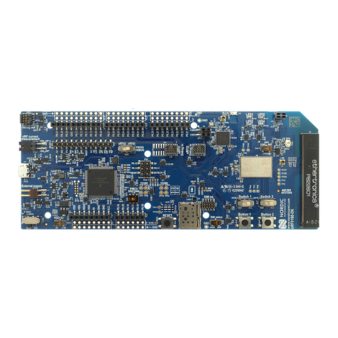
The nRF52833 DK (PCA10100) comes with a Near Field Communication (NFC) antenna.
Figure 1: nRF52833 DK (PCA10100) and NFC antenna
Hardware files
The hardware design files including schematics, PCB layout files, bill of materials, and Gerber files for the
nRF52833 DK are available on the product page.
3.2 Related documentation
In addition to the information in this document, you may need to consult other documents.
4452_198 v1.0.1 7

5Nordic tools and downloads
Once you have your kit set up you can start developing. Our software tools help you develop and test your
device through all the steps in the software development cycle.
Development IDE
Pick one of the IDEs with a compiler supported by Nordic:
IDE Windows Linux OSX
SEGGER Embedded
Studio (SES)
Yes Yes Yes
MDK-ARM Keil µVision Yes No No
GNU/GCC Yes Yes Yes
IAR Yes No No
SES is the recommended platform. It is free for use with nRF devices.
Essential tools
You need to download these Nordic tools to develop with our devices.
Tool Description Download Documentation Protocol
SDK
(Software
Development
Kit)
Application
examples, source
files, SoftDevices
Windows/Linux nRF5 SDK v16.0.0
nRF5 SDK for Mesh
v4.1.0
nRF5 SDK for Thread
and Zigbee v4.0.0
BLE/ANT
Bluetooth
Mesh
Thread and
Zigbee
nRF
Command
Line Tools
Collection of
command line
tools, like nrfjprog,
mergehex
nRF Command Line Tools nRF Command Line
Tools
BLE/ANT
Optional tools
These tools are not essential, but we recommend that you use them.
4452_198 v1.0.1 10

Nordic tools and downloads
Tool Description Download Documentation Protocol
SoftDevice Wireless protocol
stack
Compatible downloads
for nRF52840
Compatible downloads
for nRF52833
Compatible downloads
for nRF52832
Compatible downloads
for nRF52811
Compatible downloads
for nRF52810
Compatible downloads
for nRF51822
Compatible downloads
for nRF51422
nRF51 SoftDevice
Specifications
nRF52 SoftDevice
Specifications
BLE/ANT
nRF Connect for
Desktop
Expandable desktop
tool with several apps,
including:
• Peer device
emulator
• Power Profiler
• Programmer
• Cloud Gateway
nRF Connect for
Desktop
nRF Connect
Bluetooth Low Energy
BLE
nRF Connect for
Mobile
Peer device emulator
app for smartphones
Android v4.3 or later
IOS v8 or later
BLE
Nordic nRF Toolbox
app
App that contains all
the Nordic apps
Android v4.3 or later
IOS v8 or later
Windows Phone v8.1
or later
BLE
nRF pynrfjprog Simple Python
interface for the
nrfjprog DLL
nRF pynrfjprog nRF5x pynrfjprog BLE/ANT
ANTware II Peer device emulator
for the ANT protocol
running on computers
ANTware II ANT
nRF Sniffer App for monitoring on-
air traffic
nRF Sniffer download nRF Sniffer for
Bluetooth LE
BLE
nRF Thread Topology
Monitor
Tool for visualizing
Thread mesh network
topology in real time
nRF Thread Topology
Monitor
nRF Thread Topology
Monitor
Thread
Thread Border
Router
Gateway for
connecting Thread
Thread Border Router Thread Border Router Thread
4452_198 v1.0.1 11

6Start developing
After you have set up the DK and installed the toolchain, it is time to start developing.
There are several ways to continue from here, depending on which networking protocol you want to use.
• For nRF5 SDK for Bluetooth Low Energy, ANT, or proprietary 2.4Ghz (nRF5 Series devices), see nRF5
SDK Getting Started.
• For nRF5 SDK for Mesh (nRF5 Series devices), see Getting Started with Mesh.
• For nRF5 SDK for Thread and Zigbee, see Getting Started with Thread and Zigbee.
See also Software development Getting Started Guides for guidance for the main Integrated Development
Environment (IDE)s .
4452_198 v1.0.1 13

7Interface MCU
The interface MCU on the nRF52833 DK runs SEGGER J-Link OB interface firmware and is used to program
and debug the firmware of the nRF52833 SoC.
Figure 2: Interface MCU
7.1 IF Boot/Reset button
The nRF52833 DK is equipped with an IF Boot/Reset button (SW5).
This button is connected to the interface MCU on the DK and has two functions:
• Resetting the nRF52833 SoC.
• Entering bootloader mode of the interface MCU.
During normal operation the button will function as a reset button for the nRF52833 SoC. For this to work,
pin reset on P0.18 needs to be enabled in the SoC.
The button is also used to enter the bootloader mode of the interface MCU. To enter the bootloader
mode, keep the reset button pressed while powering up the DK until LED5 starts to blink. You can power
up the DK either by disconnecting and reconnecting the USB cable or by toggling the power switch (SW8).
Note: Pin reset can be enabled by adding the CONFIG_GPIO_AS_PINRESET variable to the compiler
preprocessor macros. The way of doing this depends on the IDE/toolchain in use:
• When using SEGGER Embedded Studio, go to Project > Edit Options > Code > Preprocessor >
Preprocessor Definitions and add the CONFIG_GPIO_AS_PINRESET variable.
• When using Keil, go to Project > Options for Target > C/C++ > Preprocessor Symbols > Define
and add the CONFIG_GPIO_AS_PINRESET variable.
If your program does not enable pin reset, this functionality can also be enabled on an already
programmed device by calling nrfjprog.exe with argument --pinresetenable. To disable
pinreset again, reprogram with --chiperase.
7.2 Virtual COM port
The onboard interface MCU features a UART interface through a virtual COM port.
4452_198 v1.0.1 14

Interface MCU
The virtual COM port has the following features:
•Flexible baud rate setting up to 1 Mbps.1
• Dynamic Hardware Flow Control (HWFC) handling.
• Tri-stated UART lines when no terminal is connected.
The table below shows an overview of the UART connections on the nRF52833 SoC and the interface MCU.
GPIO nRF52833 nRF52833 UART
P0.05 RTS
P0.06 TXD
P0.07 CTS
P0.08 RXD
Table 1: Relationship of UART connections on nRF52833 and interface MCU
The UART signals are routed directly to the interface MCU. The UART pins connected to the interface MCU
are tri-stated when no terminal is connected to the virtual COM port on the computer.
Note: The terminal software used must send a Data Terminal Ready (DTR) signal to configure the
UART interface MCU pins.
The P0.05 (Request to Send (RTS)) and P0.07 (Clear to Send (CTS)) can be used freely when HWFC is
disabled on the SoC.
7.3 MSD
The interface MCU features an MSD. This makes the DK appear as an external drive on your computer.
This drive can be used for drag-and-drop programming. However, files cannot be stored on this drive. By
copying a HEX file to the drive, the interface MCU will program the file to the device.
Note:
• Windows might try to defragment the MSD part of the interface MCU. If this happens, the
interface MCU will disconnect and be unresponsive. To return to normal operation, the DK must
be power cycled.
• Your antivirus software might try to scan the MSD part of the interface MCU. Some antivirus
programs trigger a false positive alert in one of the files and quarantine the unit. If this happens,
the interface MCU will become unresponsive.
• If the computer is set up to boot from USB, it can try to boot from the DK if the DK is connected
during boot. This can be avoided by unplugging the DK before a computer restart, or changing
the boot sequence of the computer.
You can also disable the MSD of the kit by using the msddisable command in J-Link Commander. To
enable, use the msdenable command. These commands take effect after a power cycle of the DK and
stay this way until changed again.
1Baud rate 921 600 is not supported through the virtual COM port.
4452_198 v1.0.1 15

8Hardware description
The nRF52833 DK (PCA10100) can be used as a development platform for the nRF52833 SoC. It features an
onboard programming and debugging solution.
In addition to radio communication, the SoC can communicate with a computer through USB and a virtual
COM port provided by the interface MCU.
8.1 Hardware drawings
nRF52833 DK hardware drawings show both sides of the PCA10100.
Figure 3: nRF52833 DK (PCA10100) front view
Figure 4: nRF52833 DK (PCA10100) back view
8.2 Block diagram
The block diagram shows the connections between the different blocks.
4452_198 v1.0.1 16

Hardware description
External
supply
Current
measurement
USB
Battery
Buttons
LEDs
GPIO
Matching
network
Osc
32.768 kHz
IF BOOT/RESET
Osc
32 MHz
Debug in
Debug out
RF connector
USB
Li-ion
nRF only mode
switch
Power switch
Analog switch
nRF power
source switch
Analog switch
nRF52833
Power supply
circuitry
Interface MCU
Antenna
Figure 5: Block diagram
8.3 Power supply
The nRF52833 DK has multiple power options.
The power options are:
• USB connector J2 for the interface MCU (5 V)
• USB connector J3 for the nRF52833 SoC (5 V)
• Lithium polymer (Li-Po) battery connectors J6 or P27 (2.5–5.0 V)
• VIN 3–5 pin on P20 (3.0–5.0 V)
• External supply on P21 (1.7–3.6 V)
• Coin cell battery
Figure 6: Power supply options (front)
4452_198 v1.0.1 17

Hardware description
Figure 7: Power supply options (back)
8.3.1 5 V power sources
The nRF52833 DK has a 5 V boost regulator.
It gives a stable 5 V output from four possible sources:
• USB connector J2 for the interface MCU
• USB connector J3 for the nRF52833 SoC
• Li-Po polymer battery connectors (J6 or P27)
• VIN 3–5 V pin on P20
Each of these sources has a reverse protection diode to prevent current flowing in the wrong direction if
multiple sources are connected at the same time.
Figure 8: 5V regulator and protecting diodes
8.3.2 VDD power sources
The main supply (VDD) can be sourced from the 5 V domain, external power supply, and coin cell battery.
For the 5 V domain, there are two regulators, one fixed 3 V buck regulator and one voltage follower
regulator that follows the VDD_nRF voltage. The coin cell battery and external power supply are not
regulated.
• 5 V domain:
• Fixed 3 V buck regulator
• VDD_nRF voltage follower
• External power supply
• Coin cell battery
For more information about power sources, see section nRF52833 power source on page 22.
The power sources are routed through a set of load switches, which are controlled by logic to prioritize the
power sources in the correct manner.
4452_198 v1.0.1 18

Hardware description
Figure 9: Power supply circuitry
4452_198 v1.0.1 20
Table of contents
Other Nordic Computer Hardware manuals
Popular Computer Hardware manuals by other brands

ekwb
ekwb EK-FC 770 GTX DCII INSTALLATION AND MOUNTING MANUAL

Novus
Novus NVQ-4C user manual

HP
HP A5830AF-48G user guide

SSV
SSV DIL/NetPC DNP/8331 Hardware reference

Texas Instruments
Texas Instruments Hercules RM48 instruction manual

Delta Electronics
Delta Electronics Hybrid Choke CDE20H Specification sheet