Nordmann Engineering NRC-5V User manual
INSTALLATIONSANLEITUNG
INSTALLATION INSTRUCTIONS
INSTRUCTIONS D’INSTALLATION
Raumfeuchtefühler
Room humidity sensor
Sonde d’humidité ambiante
Nordmann NRC-5V
2561862 DE/EN/FR 1304
NORDMANN
ENGINEERING
NORDMANN
ENGINEERING
Dampfluftbefeuchter econoVap

2
1 Funktionsbeschreibung
Der Nordmann NRC-5V (Ausgangssignal
0…5 VDC) dient zur Feuchtemessung in
Räumen. Für die Feuchtemessung wird ein
kapazitiver Feuchtesensor verwendet. Der
Mikroprozessor erfasst die Feuchtigkeit einmal
pro Sekunde und berechnet ein Durchschnitt-
signal über eine bestimmte Zeit in Sekunden
und generiert dauraus ein Ausgangssignal.
Die angewandte Messtechnologie garan-
tiert eine hervorragende Zuverlässigkeit und
Langzeitstabilität.
2 Sicherheit
Beachten Sie bitte alle lokalen Vorschriften
betreffend die Ausführung von elektrischen
Installationen.
Die Installationsarbeiten dürfen nur durch
ausgewiesenes Fachpersonal (Elektriker
oder Fachkraft mit gleichwertiger Ausbil-
dung) durchgeführt werden.
Achtung Stromschlaggefahr! Vor Beginn
der Installationsarbeiten ist das Gerät, an das
der NRC-5V angeschlossen werden soll, vom
Stromnetz zu trennen. Der Wiederanschluss
an das Stromnetz darf erst nach Fertigstellung
sämtlicher Installationsarbeiten erfolgen.
Achtung! Die elektronischen Bauteile im In-
nern des NRC-5V sowie des Befeuchters sind
sehr empndlich gegen elektro statische Entla-
dungen. Zum Schutz dieser Bauteile müssen
für alle Installationsarbeiten Massnahmen
gegen Beschädigung durch elektrostatische
Entladung (ESD–Schutz) getroffen werden.
3 Lieferumfang
Der Lieferumfang umfasst:
– Feuchtefühler Nordmann NRC-5V
– Befestigungsmaterial
– Installationsanleitung
4 Platzierung
Der Nordmann NRC-5V wird mindestens
1,5 m über dem Fussboden direkt an die
Wand montiert.
Beachten Sie folgende Platzierungshinweise:
–Den Nordmann NRC-5V nicht in Nischen,
hinter Vorhängen, etc. platzieren.
–Den Nordmann NRC-5V nicht in der Nähe
von Wärmequellen, im Bereich mit direktem
Luftzug oder direkter Sonneneinstrahlung
platzieren.
1 Functional description
Nordmann NRC-5V (output signal of the
sensor 0...5 VDC) serves for the humidity
measurement in rooms. For the humidity
measurement a capacitive humidity sensor is
used.The microprocessor samples the humid-
ity once per second. It calculates an averag-
ing signal over a preset number of seconds
and generates the output signal. The applied
measuring technology guarantees excellent
reliability and long term stability.
2 Safety
Please observe all local regulations concern-
ing the electric installation.
The installation work must be performed
only by adequately qualied personnel
(electrician or workman with equivalent
training).
Warning - danger of electric shock! Be-
fore starting the installation work the unit to
which the NRC-5V will be connected must
be disconnected from the mains and may be
reconnected to mains only after all installation
work has been completed.
Warning! The electronic components inside
the NRC-5V and the humidier are very sus-
ceptible to electrostatic discharges. For the
protection of these components, measures
must be taken during all installation work
to prevent damage caused by electrostatic
discharge (ESD–protection).
3 Delivery
The delivery includes:
– Humidity sensor Nordmann NRC-5V
– Fixing material
– Installation instructions
4 Mounting location
The Nordmann NRC-5V is mounted at least
1.5 m above the oor directly to the wall.
Observe the following placement notes:
–Do not place the Nordmann NRC-5V in
niches, behind curtains, etc..
–Do not place the Nordmann NRC-5V near
heat sources, within the area with direct
air draft or direct sunlight.
1 Description de fonctionnement
Le Nordmann NRC-5V (signal de sortie de
sonde 0...5 VDC) est destiné à effectuer la
mesure d’humidité dans locaux. La mesure
d’humidité s’opère au moyen d’une sonde
hygrométrique capacitive. Le microprocesseur
saisit l’humidité une fois par seconde, calcule
une valeur moyenne durant une période dé-
terminée et génère un signal de sortie en
conséquence. La technologie de mesure
appliquée garantit une abilité et une stabilité
à long terme remarquables.
2 Sécurité
Veuillez observer chaque prescription lo-
cale concernent l’exécution d’installations
électriques.
Seules les personnes spécialisées compé-
tentes (électricien ou spécialiste de même
formation) sont autorisées à effectuer les
travaux d’installation.
Attention, risque de choc électrique! Avant
de commencer des travaux d’installation, sé-
parer du réseau électrique l’appareil destiné
à être raccordé à le NRC-5V. N’effectuer le
raccordement de l’humidicateur au réseau
électrique qu’au terme de tous les travaux
d’installation.
Attention! Les composants électroniques in-
tégrés dans le NRC-5V et l’humidicateur sont
très sensibles aux décharges électrostatiques.
Ces composants impliquent, lors de tous les
travaux d’installation, la prise des mesures
de précaution contre leur détérioration par
décharge électrostatique.
3 Ampleur de la livraison
La livraison comporte:
–Sonde hygrométrique NRC-5V
– Matériel de xation
– Instructions d’installation
4 Emplacement
Le Nordmann NRC-5V se monte directement
sur la paroi à 1,5 m au moins au-dessus du
plancher.
Observer les indications de placement suiv-
antes:
–Ne pas placer le Nordmann NRC-5V dans
les niches, derrière des rideaux, etc.
–Ne pas placer le Nordmann NRC-5V à
proximité des sources de chaleur, en zones
exposées à des courants d’air direct ou à
la lumière solaire directe.

3
5 Installation
1. Schraube des Gehäuses lösen und Mon-
tageplatte entfernen.
2. Montageplatte (mit der Plastikschraube
nach unten zeigend) am vorgesehenen
Ort mit zwei Schrauben an der Wand
befestigen (siehe Masszeichnung).
3. Anschlusskabel von unten ins Gehäuse
führen und gemäss dem Elektroschema
an die Anschlussklemmen anschliessen.
4. Gehäuse auf die Montageplatte aufstecken
und mit der Schraube befestigen (Schraube
nur mässig anziehen).
6 Produktspezikationen
6.1 Technische Daten
Stromversorgung / Power Supply / Alimentation de courant
Betriebsspannung / Operating voltage / Tension d’alimentation 24 V AC 50/60 Hz ± 10%, 24VDC ± 10%
Leistungsaufnahme / Power Consumption / Puissance absorbée Max. 2 VA
Klemmenanschlüsse / Terminal Connectors / Bornes Für Litzen / for wires / pour ls 0.34…2.5 mm2
(AWG 24…12)
Sensorelement / Sensor probe / Elément de sonde
Messelement / Measuring element / Elément de mesure Kapazitives Messelement / Capacitive measur-
ing element / Elément de mesure capacitif
Messbereich / Measuring range / Plage de mesure 0…100 %rF / %rh / %hr
Messgenauigkeit / Measuring Accuracy / Fidélité de mesure
100
0
±1
±2
±3
±4
±5
%rF
%rh
%hr
%rF
%rh
%hr
20 30 40 50 60 70 80 90 100
Max. rF-Toleranz bei 25 °C (77°F)
Max. RH tolerance at 25 °C (77°F)
Tolérance HR max. à 25 °C (77°F)
Hysterese / Hysteresis / Hystérésis ± 1%
Wiederholbarkeit / Repeatability / Reproductibilité ± 0.1%
Stabilität / Stability / Stabilité < 0.5% / Jahr / year / année
Signalausgänge / Signal Outputs / Sorties de signal
Analogausgänge / Analog Outputs / Sorties analogiques
Ausgangssignal / Output Signal / Signal de sortie 0...5 VDC
Auösung / Resolution / Résolution 10 Bit, 9.7 mV, 0.019.5 mA
Maximale Last / Maximum Load / Charge maximum 20 mA, 500Ω
Umgebung / Environment / Environnement
Betrieb / Operation / Exploitation IEC 721-3-3
Klimatische Bedingungen / Climatic Conditions / Conditions climatiques Class 3 K5
Temperatur / Temperature / Température -40…70°C (-40…158°F)
Feuchtigkeit / Humidity / Humidité <95 %rF nicht kondensierend / <95 %rh non-
condensing /<95 %hr sans condensation
Transport & Lagerung / Transport & Storage / Transport & entreposage IEC 721-3-2 und / and / et IEC 721-3-1
Klimatische Bedingungen / Climatic Conditions / Conditions climatiques Class 3 K3 und / and / et Class 1 K3
Temperatur / Temperature / Température -40…80°C (-40…176°F)
Feuchtigkeit / Humidity / Humidité <95 %rF nicht kondensierend / <95 %rh non-
condensing /<95 %hr sans condensation
Mechanische Bedingungen / Mechanical Conditions / Conditions mécaniques Class 2M2
5 Installation
1. Desserrer la vis du boîtier et ôter la plaque
de montage.
2. A l’endroit prévu, xer la plaque de mon-
tage (la vis en plastique montrant vers la
bas) sur la paroi avec deux vis (consulter
le dessin coté).
3. Introduire le câble de raccordement par
le bas dans l’appareil et le brancher aux
bornes de raccordement selon le schéma
électrique.
4. Placer le boîtier sur la plaque de montage
et le xer à l’aide de la vis (ne la serrer
que modérément).
6 Spécicationsdesproduits
6.1 Caractéristiques techniques
5 Installation
1. Open the screw of the housing and remove
mounting plate.
2. At the place of location x mounting plate
(plastic screw facing downwards) with two
screws (see dimensional drawing).
3. Lead connecting cable from the bottom into
the housing and connect wires to the ter-
minals according to the wiring diagram.
4. Snap housing onto the mounting plate, and
x it with the screw (do not tighten screw
too much).
6 Productspecications
6.1 Technical data
4
Standards / Standards / Standard
Konform mit / conform according to / conforme selon
EMC Standard 89/336/EEC EMEI Standard 73/23/EEC
EN 61 000-6-1/ EN 61 000-6-3
Normen Produkt / Product standards / Normes de produit
Automatische elektrische Steuerungen für Haushalt und ähnlichen Gebrauch /
Automatic electrical controls for household and similar use /
Commandes électriques automatiques pour le ménage et l’usage semblable
EN 60 730 –1
Spezielle Anforderung an temperaturabhängige Steuerungen /
Special requirement on temperature dependent controls /
Exigences spéciales concernant sur des commandes à charge de la température
EN 60 730 – 2 - 9
Schutzart gemäss EN 60529 / Degree of Protection to EN 60529 /
Genre de protection selon EN 60529
IP30 (falls korrekt montiert / if installed cor-
rectly / si installé correctement
Sicherheitsklasse / Safety Class / Classe de sécurité III (IEC 60536)
Allgemein / General / En général
Gehäuse / Housing / Boîtier ABS (feuerfest / re proof / non inammable)
Montageplatte / mounting plate / Plaque de montage Galvanisierter Stahl / Galvanised steel / Acier
galvanisé
Dimensionen Sensorgehäuse (HxBxT) / Dimensions (HxWxD) sensor housing /
Dimensions boîtier de sonde (HxLxP)
88 mm x 88 mm x 21 mm (3.5” x 3.5” x 0.8”)
Gewicht Nordmann NRC-5V (inkl. Verpackung) / Weight Nordmann NRC-5V (including
package) / Poids Nordmann NRC-5V (avec emballage)
160 g (5.6 oz)
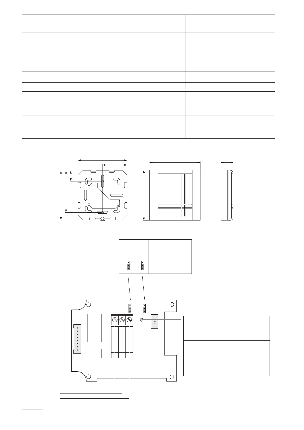
6.2 Dimensionen [mm] (")
6.3 Elektroschema/Konguration
24V AC/DC
1
0V / GND
2
H OUT
3
STATUS
LED
JP1 JP3
RH OUT
0V / GND
24 V AC/DC ±10%
JP1 JP3
Signaltyp
Signal type
Type de signal
3
2
1
3
2
10-5V
Status LED
brennt nicht: keine Spannung
5 s Blinken: Normal
1 s Blinken: Sensorelement defekt
No light: no power
5 s blinking: Normal
1 s blinking: Sensor element defective
ne brûle pas: pas d’alimentation de tension
5 s clignoter: Normal
1 s clignoter: Elément de sonde defectueuse
6.2 Dimensions [mm] (")
6.3 Schémaélectrique/Conguration
6.2 Dimensions [mm] (")
6.3 Wiringdiagram/Conguration
85 (3.4)
85 (3.4)
87.5 (3.5) 21 (0.8)
87.5 (3.5)
72 (2.8)
42.5 (1.7)
65 (2.6)

© Nordmann Engineering Ltd., Printed in Switzerland
Technische Änderungen vorbehalten
Technical modifications reserved
Sous réserve de modifications techniques

Manufacturer:
Nordmann Engineering Ltd.
www.nordmann-engineering.com, info@nordmann-engineering.com
NORDMANN
ENGINEERING
NORDMANN
ENGINEERING
Dampfluftbefeuchter econoVap
Reg.No. 40002-2
Table of contents
Other Nordmann Engineering Accessories manuals


