Nordson ASYMTEK TCM-2200 User manual

Operation Manual, Troubleshooting and
Maintenance Guide for Oven Models
TCM-2200, TCM-3300 & TCM-4600
P/N 7222937
Revision: A

NOTICE
This is a Nordson ASYMTEK publication, which is protected by copyright. Original copyright date
2004. No part of this document may be photocopied, reproduced, or translated to another
language without the prior written consent of Nordson ASYMTEK. The information contained in
this publication is subject to change without notice.
Manuals on the Internet
For the convenience of Nordson ASYMTEK customers and field service representatives, copies
of Nordson ASYMTEK manuals can be downloaded from:
Contact Us
http://www.nordsonasymtek.com
Nordson ASYMTEK welcomes requests for information, comments, and inquiries about its
products. Please contact us using the information below:
Headquarters 2762 Loker Avenue West
Carlsbad, CA 92010-6603
USA
Toll Free: 1-800-ASYMTEK (1-800-279-6835)
Tel: +1-760-431-1919
Fax: +1-760-431-2678
E-mail: info@asymtek.com
Website: www.asymtek.com
Technical Support
USA: 1-800-ASYMTEK (1-800-279-6835)
Other regions: www.nordsonasymtek.com Tech Support
Trademarks
Asymtek®, Century®, Select Coat®, and Easy Coat® are registered trademarks of Nordson ASYMTEK.
Microsoft®, Windows®, and Windows®XP are registered trademarks of Microsoft Corporation.
© Nordson, 2011

i
Contents
Introduction
I. How to Use this Manual--------------------------------------------------------------------------- 3
II. Safety Precautions --------------------------------------------------------------------------------- 4
Facility Installation
I. Unpacking ------------------------------------------------------------------------------------------ 17
II. General Operating Conditions --------------------------------------------------------------- 18
III. Power Requirements---------------------------------------------------------------------------- 18
IV. Lighting Requirements------------------------------------------------------------------------- 19
V. Exhaust Requirements------------------------------------------------------------------------- 19
VI. Leveling the Machine --------------------------------------------------------------------------- 19
VI. Computer Installation--------------------------------------------------------------------------- 20
VIII. Optional Battery Backup Installation------------------------------------------------------ 21
IX. Final Things to Do ------------------------------------------------------------------------------- 21
X. Sprinkler Fire Suppression System-------------------------------------------------------- 21
XI. Facility Drawings--------------------------------------------------------------------------------- 21
Operating System Software Guide
A. Starting the Program------------------------------------------------------------------------------ 25
B. Main Operating Screen --------------------------------------------------------------------------- 26
C. Selecting Screen and Function---------------------------------------------------------------- 27
D. Scheduling Calendar Events ------------------------------------------------------------------- 42
E. Setting Up User Security------------------------------------------------------------------------- 43
F. Enable Data Logging and Interval Time----------------------------------------------------- 44
G. Channel Trend Plot Screen Setup ------------------------------------------------------------ 45
H. New User Log On----------------------------------------------------------------------------------- 46
I. User Log Off ----------------------------------------------------------------------------------------- 46
J. Acknowledge Alarm-------------------------------------------------------------------------------- 46
K. Shutting Down the System---------------------------------------------------------------------- 47
L. Editing Parameters from the Channel Setup Screen------------------------------------ 47
M. Modifying A Recipe-------------------------------------------------------------------------------- 48
N. Loading A Recipe ---------------------------------------------------------------------------------- 48
O. Deleting A Recipe---------------------------------------------------------------------------------- 48
P. Software Version ----------------------------------------------------------------------------------- 48
Q. System Setup---------------------------------------------------------------------------------------- 49
Standard and Optional Equipment Operating Guide
I. Alarm and Warning Options and Operation ----------------------------------------------- 63
A. Light Tower Output ------------------------------------------------------------------------- 63
B. Audible Alarm Option ---------------------------------------------------------------------- 63
C. Independent Alarm Sensor Option (IAS)--------------------------------------------- 64
D. Power Hood Lifts ---------------------------------------------------------------------------- 64
II. Battery Backup Option --------------------------------------------------------------------------- 64
III. Edge Hold Conveyor System and Options------------------------------------------------- 64
A. Description and Standard Operation-------------------------------------------------- 64
B. Computer Controlled Edge Hold Positioning Option---------------------------- 64
C. Center Board Support Option ----------------------------------------------------------- 65
D. Board Counter/Board Drop Option ---------------------------------------------------- 66
E. Upstream and Downstream Machine Interfaces ---------------------------------- 66

ii
Troubleshooting Guide
Index------------------------------------------------------------------------------------------------------------- 69
I. No Power to the Machine----------------------------------------------------------------------- 71
II. Communication with the Oven Was Lost-------------------------------------------------75
III. Low Deviation of A Heat Zone or A Zone Not Reaching Temperature ---------- 80
IV. High Deviation of A Heat Zone or A Zone Overheating ------------------------------ 83
V. High Process Alarm------------------------------------------------------------------------------ 86
VI. Zone Temperature Is Not Stable ------------------------------------------------------------- 89
VII. Heat Rise Rate Alarm---------------------------------------------------------------------------- 92
VIII. Software Lock-Up or Odd Behavior--------------------------------------------------------- 93
IX. Conveyor Not Moving --------------------------------------------------------------------------- 93
X. Conveyor Speed Controller Adjustment -------------------------------------------------- 96
XI. Conveyor Speed Not Stable------------------------------------------------------------------- 99
XII. Machine In A Warning Condition ------------------------------------------------------------ 101
XIII. Tripped Breakers---------------------------------------------------------------------------------- 101
Maintenance Procedures
Index------------------------------------------------------------------------------------------------------------- 105
I. Replacing A Top IR Panel---------------------------------------------------------------------- 107
II. Replacing A Bottom IR Panel (Removing the Edge Hold Conveyor) ------------ 108
III. Adjusting the Slip Clutch (Edge Hold Conveyor w/o mesh belt)------------------ 109
IV. Replacing an SSR (Solid State Relay)------------------------------------------------------ 110
V. Replacing A Thermocouple ------------------------------------------------------------------- 111
VI. Replacing Carbon brush of DC motor ----------------------------------------------------- 112
VII. Lubrication------------------------------------------------------------------------------------------ 113
VIII. Verifying Accuracy of the System----------------------------------------------------------- 114
IX. Profiling---------------------------------------------------------------------------------------------- 116
X. PM Schedule --------------------------------------------------------------------------------------- 119
Parts Ordering Information------------------------------------------------------------------------------- 120
EC Declaration Conformity------------------------------------------------------------------------------- 121

1
Introduction

2

3
I. How to Use this Manual
Congratulations on the purchase of your Asymtek oven. This equipment is designed to satisfy a
wide range of solder Cure and PCB curing applications. When properly used and maintained
within operating limits described throughout this manual the machine will provide years of trouble
free service.
This manual is applicable to all Asymtek oven models TCM-2200, TCM-3300 and TCM-4600
running WINDOWS-XP based software. It contains installation, operation, troubleshooting and
maintenance procedures for electrical and mechanical systems on all models, including most of
the common optional equipment available for the ovens. Electrical schematics, nitrogen plumbing
diagrams and additional information may be found at the back of this manual and/or OEM
instruction manuals.
CAUTION: Although most installation and service
routines can be performed easily, extreme caution
should be exercised when working with live electrical
circuits. ONLY a trained electrical technician or
engineer following all required codes and
lockout/tagout procedures should perform this work.
The first section of the manual describes for the technician the requirements and necessary steps
to uncrate and install the oven.
For a detailed explanation of software operation, please refer to the section entitled “Operating
System Software Guide”.
The section entitled “Standard and Optional Equipment Operating Guide” explains each of the
features and available standard options. It includes operating instructions as well as schematics
and diagrams.
To use the troubleshooting guide, please refer to the contents to select the troubleshooting
section most applicable to the symptoms exhibited by the machine. It is recommended that the
technician read the entire applicable section first before starting the troubleshooting procedure.
Once he is familiar with all the required tests, he may then decide upon the most logical
troubleshooting steps to take. The troubleshooting section contains a page useful for determining
computer channel assignments for the various heating zones as well as a guide for determining
which SSR (Solid State Relay) is controlling a particular zone. It also includes a section that will
instruct the technician as to which covers will need to be removed to access internal components.
The technician should refer to the final section of the manual for any maintenance procedures
that need to be performed.
If any further assistance should be required, contact Asymtek Technical Support Group;
Asymtek Technical Support Group;
In the U.S.: 1-800-ASYMTEK (1-800-279-6835)
From outside the U.S.: +1-760-431-1919
or
Email: [email protected]

4
To perform the procedures presented in this manual you may need the following equipment:
•Medium and large Phillips head screwdrivers
•Large, medium and small flat blade screwdrivers
•Set of Allen (hex) keys: Metric (1.5mm to 10mm)
•Set of open end wrenches or socket set: Metric (9mm to 20mm)
•Channel-lock pliers or pipe wrench with 3”(75mm) capacity
•Wire cutters (diagonal cutters)
•Needle-nose pliers
•Wire strippers
•Terminal crimpers with assorted terminals
•Multimeter (voltmeter/ohmmeter)
II. Safety Precautions
II.1. Overview
This chapter provides safety guidelines that should be followed when operating the Cure Oven
System. These guidelines ensure personal safety and protect equipment during installation,
operation, maintenance, troubleshooting, and other potentially dangerous procedures. Safety
training is available upon request.
Facility
Installation The oven should be uncrated and installed using an appropriate forklift and
following the procedures as outlined. Failure to use appropriate equipment
may result in personal injury and/or property damage.
The oven should be connected to power by a qualified electrician and must
comply with all appropriate electrical and safety codes. See instruction
manual Section III in Facility Installation for power supply requirements.
Failure to follow electrical codes or the use of under-rated supply
conductors may cause property damage and may subject the operator to
hazardous voltages.
The exhaust ducting for the oven should be designed and installed by a
qualified HVAC technician capable of calculating air flow from suction
blowers and flow losses in upstream and downstream ducting. Improper
exhausting may allow flux fumes to be inhaled by the operator.
Special Precautions should be taken if the unit is installed in a sprinklered
room or building. Refer Sprinkler System in Facility Installation, Section XI.
Ensure packing material is removed.
Read instruction manual.
Refer Leveling of the oven in Facility Installation, Section VII.
Operating the
Equipment When oven is in use, the edge hold conveyor system and other machine
components will become hot. Please observe all hot surface warning
placards applied to the machine. Please also observe all other warning
placards and instructions. Do not open the oven while it is in operation.
This will expose the operator to high temperature air.
Power Hood Lifts When closing the top shell of the oven, be aware that long hair or loose

5
fitting clothing may become entangled in the system. The shell may also
pose a crushing threat to bodily extremities.
Software
Operation Do not alter settings in the system software beyond that which is described
in this manual without first contacting the factory. Doing so may affect safe
operation of the machine.
Nitrogen
Operation Even though nitrogen is an inert substance, a few simple precautions
should be made. Proper ventilation in the area where the system is being
used must be maintained to keep the oxygen level in the air at safe levels.
Otherwise the continuous flow of nitrogen can displace the air and deplete
the normal oxygen level. Create sufficient ventilation in the area of the
Cure oven to exhaust the excessive nitrogen laden air and replace it with
normal atmosphere. Installation of a room oxygen monitoring system is
recommended especially if the oven is installed in a small-enclosed area.
Edge Hold/Mesh
Belt Operation
Caution must be exercised when working near the belt or conveyor
systems. Do not operate the system with guards removed and be aware of
all pinch point warning decals. Also, be aware that long hair or loose fitting
clothing may become entangled in the system. Should this occur, an
EMERGENCY STOP button is located at each end of the oven. Pressing
this button will immediately stop the conveyor system.
Troubleshooting
and Maintenance Please be aware that although many service routines can be performed
easily, extreme caution should be exercised when working with live
electrical circuits. ONLY a trained electrical technician or engineer should
perform this work. Before removing any panels, all power to the oven
should be switched off and the temperature should be at room ambient.
While system components are fully tested and rated for long life, it is the responsibility of
the customer to properly maintain the equipment after the warranty period to ensure the safety
and functionality of the machine. Improper maintenance and checking can result in system or
subsystem failures that are not the responsibility of the manufacturer. This includes the cleaning
of the various areas, the tightening of screws, the confirmation of proper voltage and current
draws, appropriate lubrication, proper exhaust, proper handling during movement of the machine,
and periodic checks of each of the subsystems for functionality.
II.2. Cautions and Warnings
Three basic types of alert boxes are used in this manual to warn personnel during operation,
maintenance, and troubleshooting of the Cure Oven System:
DANGER! means the action will cause serious injury or death to
personnel if proper procedures are not followed.
WARNING! means the action may result in serious injury or death if
proper procedures are not followed.
CAUTION! means the action may cause damage to equipment and/or
minor to moderate injury to personnel if proper procedures are not
followed.

6
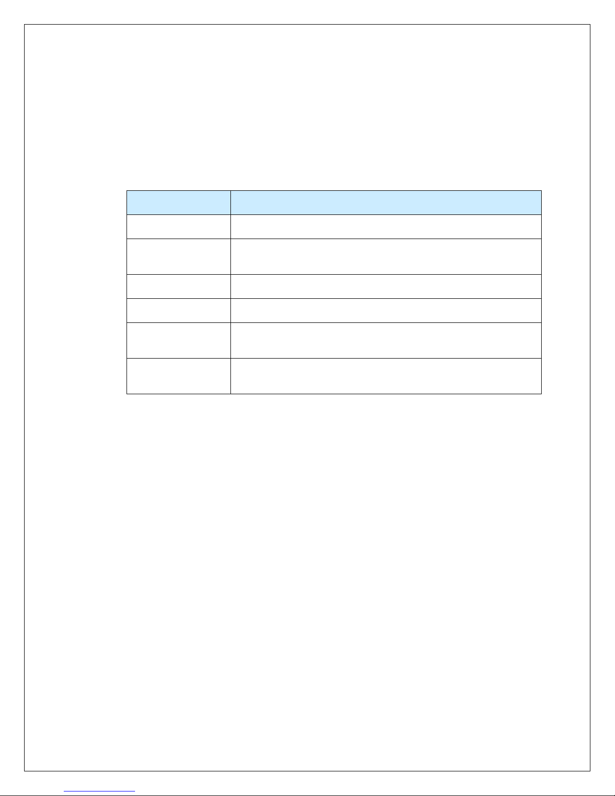
II.3. Cure Oven System Safety Labels
Safety labels affixed to system hardware are used to make personnel aware of potential hazards
and remind them to take necessary safety precautions. Table II-1 describes them in detail.
Table II-1 Safety Hazard Labels
Label Part Number Description
2545 Hazardous Voltage Warning - Warns
personnel of areas where high voltage is
present which may cause severe injury
or death.
3628 Hot Surface Warning - Warns personnel of
hot surfaces that may cause burns if touched.
3627 Moving Parts Warning - Warns personnel to
keep hands and fingers away from
mechanisms that could cause injury.
7
II.4. Basic Safety Precautions
When used properly, the Asymtek Cure Oven System provides safe and reliable service. The
purpose of this advisory is to point out possible hazards that may be encountered during
operation, maintenance, and servicing of your system. This equipment is designed with IP32
code.
WARNING! Only qualified and authorized personnel should perform
equipment, installation, setup, maintenance, troubleshooting, and repair.
II.5. Electrical Hazards
WARNING! Always disconnect the equipment from the power source and
attach a lockout device to the electrical disconnect before performing any
maintenance or repair.
II.6. Fire Hazard
WARNING! Always use class-c fire extinguisher in case of any fire in Asymtek
Cure oven.
In case of any leakage of flux gases or any smoke form the oven, turn on utility room exhaust to
clear area.

8
II.7. Environmental Hazards
Hazardous Material
CAUTION! Cleaners are used during maintenance and servicing should be
considered hazardous material. Consult with your facility safety officer and the
manufacturer’s Material Safety Data Sheet for instructions concerning proper
disposal of hazardous materials. Contact Asymtek if you have any questions.
See Maintenance Procedure section for anticipated change-out frequency,
quantity and potential for contamination from the process.
CAUTION! Do not use flammable solvents to clean.
Component Disposition
Cleaners: ALPHA
saponifier/Vigon RC101 Discard in accordance with local safety/environmental regulations.
Hazardous Waste
CAUTION! Solid wastes generated during system maintenance and servicing
should be considered hazardous waste. Consult with your facility safety officer
and the manufacturer’s Material Safety Data Sheet for instructions concerning
proper disposal of hazardous materials. Contact Asymtek if you have any
questions.
CAUTION! Customer should be aware that the flux they add to the oven will be
exhausted.
Component Disposition
Interior deposits and
Dirty rags Discard in accordance with local safety/environmental regulations.
Cleaned Used Flux Discard in accordance with local safety/environmental regulations.
Process Exhaust
CAUTION! Exhaust discharge hazards are dependent upon the process gas
(es) used and the material(s) being treated.
The chemistry of exhaust discharges should be evaluated for potential hazards
by trained safety/environmental engineers prior to system start-up. Contact
Asymtek if you have any questions.
9
Smoke from Electrical Fault
CAUTION! Smoke generated by electrical faults inside the Cure Oven System
may be exhausted into the surrounding area. Personnel should avoid inhaling
the smoke because it might contain hazardous substances.
The chemistry of the smoke should be evaluated for potential hazards by
trained safety/environmental engineers prior to system start-up. Contact
Asymtek if you have any questions.
Hazardous Energy
CAUTION! Thermal Energy: Oven may be HOT, wait until oven cools down or
proper insulated gloves should be used. See Operating System Software Guide,
Section-K.
CAUTION! BBU Energy: Oven BBU will be turned OFF remotely by rotary
switch OFF position with one bip sound. If BBU bip sounds more than once,
turn BBU OFF manually by pressing ON/OFF button (top first). To access BBU
unit, open right rear base bottom panel where BBU is mounted in the base.
10
II.8. Decommissioning Procedures
The Asymtek Cure Oven System should provide you with years of safe and reliable service.
When it becomes necessary to decommission the system, the components should be disposed of
as specified in Table II-2.
Table II-2 Recommended Decommission Procedures
Component Disposition
Chamber Residue Discard in accordance with local safety/environmental regulations.
Aluminum Parts Recycle aluminum Chamber, panels, shelves, doors, and
hardware.
Steel Parts Recycle all steel parts.
Copper Wiring Recycle any copper wiring.
Electronic
Components Discard in accordance with local safety/environmental regulations.
Plastics Recycle or discard in accordance with local safety/environmental
regulations.

11
II.9. Cure Oven System Safety Features
The Asymtek Cure Oven System is designed with several integrated safety features to protect
against personal injury and equipment damage. These features include the emergency shut off
button and the safety interlocks.
II.9.1. Emergency Stop
The Asymtek Cure Oven System is equipped with a large, clearly marked, front console-mounted
emergency stop (E-Stop) push button. When activated, the power to the system heaters is
disconnected, the system conveyor is stopped, & the oven goes into “Cooldown” mode. This is
accomplished via relay contacts that set the heater power contactor to the OFF state and stop
system conveyor operation. To reset E-Stop function, twist emergency stop button and press “E-
Stop Reset”, oven stays in “Cooldown” mode. To restore full power to the system heaters and
system conveyor, reset system software and load a wakeup or hot job recipe from the system
software.
.
CAUTION! When the Emergency stop button is activated, the Main Circuit
Breaker, Rotary Switch, the line side of the Main Power contactor and
Transformer are still energized. Before accessing the system’s Lower
Enclosure, perform the lockout/tag out procedure in Error! Reference source
not found. to prevent serious injury to personnel.

12
II.10. Light Tower Status Lights
The Asymtek Cure Oven System includes a Light Tower (Figure II-1) that constantly shows the
status of the current operation. Table II-3 describes the meaning of Light Tower status lights.
Figure II-1 Cure Oven Light Tower Status Lights
Table II-3 Light Tower Status Lights
Light Color System Status Reasons
FLASHING
RED ALARM A system alarm is present. Refer to Section
Troubleshooting for recovery information.
GREEN OK The system is ready to process material.
FLASHING
YELLOW WARNING OR
NEW JOB The System warning, Board drop, Board backup
or Job start up.
II.10.1. Audible Alarm
This option consists of an audible signal that sounds when the system goes into an alarm mode
or board drop occurs. The signal is activated whenever the red light on the light tower is
illuminated. In the event of an alarm, the light tower turns red, the audible alarm sounds and the
machine load the Cooldown job.
The operator can silence the audible alarm by acknowledging it. See the “Operating System
Software Guide” section.
RED
YELLOW
GREEN

13
II.11 System Lockout
During maintenance and servicing tasks, prevent injury to personnel by locking out and tagging
out system power supply. Follow equipment shut down procedure as described below:
1. Notify affected personnel before beginning any maintenance, servicing, and
troubleshooting.
2. Load the Cooldown program.
a. From the main toolbar click the Cooldown icon or from the menu bar select Mode
then select Cooldown from the dropdown menu.
b. After all heat zones have cooled below a pre-determined temperature (factory
default is 95° C) the blowers and conveyor drive motor will turn off. (Opening the
oven hood will allow the oven to cool faster but be aware that the oven will be
blowing hot air.)
3. Continue the shutdown process by clicking on the Exit icon on the main toolbar or
selecting Mode then Shutdown+Exit from the drop down menu. This will close the Oven
Operating Software and return the user to the desktop.
4. From the desktop the user can shut down the PC before turning off power to the oven.
5. Turn oven power OFF by rotating the main rotary power switch to the OFF (0) position.
a. This will also remotely shut off BBU unit if equipped. BBU unit will beep once
during shutdown.
6. Turn off supply power to the oven at facility three phase circuit breaker feeders.
7. Obtain locks and tags from facility lock-out/tag-out station.
8. Lock-out and tag-out the following energy source disconnects:
a. Facility three-phase power supply circuit breaker.
b. Main oven power rotary switch.
9. Check AC power at X1 (primary) terminal block. Measure AC voltage between phases
L1- L2, L1- L3, L2-L3 using a voltmeter. Meter should read zero volts.
10. Perform maintenance, servicing and troubleshooting as necessary.
II.12 Restoring system to service
Following maintenance and tasks restore the system to service as follows:
1. Make sure all doors, panels, and guards are in place.
2. When equipment is safe to run, remove all locks and tags from all locked out devices.
3. Turn main power supply facility circuit breaker “ON”.
4. Turn rotary switch on oven to ON (I) position.
5. Reset E-stop circuit by pressing blue push button.
6. Follow recommended start-up procedures described in Operating System Software
Guide, Section-A

14

15
Facility Installation

16
This manual suits for next models
2
Table of contents
Other Nordson ASYMTEK Oven manuals

Popular Oven manuals by other brands


NEFF
NEFF B4ACM5HH0B User manual and installation instructiions

Valencia Euro
Valencia Euro EV6004WH user manual

Frigidaire
Frigidaire FGET2745KB - Gallery 27" Double Electric Wall... Wiring diagram

Frigidaire
Frigidaire PLEB30S8A Specifications

King Edward
King Edward CLASSIC 25 operating instructions

HearthStone
HearthStone Patio Oven 4.5 user manual