EnglishDeutsch
 logo
Brands
  1. Home
  2. •
  3. Brands
  4. •
  5. Nordson
  6. •
  7. Recording Equipment
  8. •
  9. Nordson iControl User manual

Nordson iControl User manual

Other manuals for iControl

4

Other Nordson Recording Equipment manuals

Nordson iControl Series Manual instruction

Nordson

Nordson iControl Series Manual instruction

Nordson iControl User manual

Nordson

Nordson iControl User manual

Popular Recording Equipment manuals by other brands

Philips CDR 765 null

Philips

Philips CDR 765 null

Philips CDR770 null

Philips

Philips CDR770 null

KV2 Audio 500 Series user guide

KV2 Audio

KV2 Audio 500 Series user guide

Robotics Technologies microBus-Cam II installation manual

Robotics Technologies

Robotics Technologies microBus-Cam II installation manual

Seca 460 quick start guide

Seca

Seca 460 quick start guide

Cognex MVS-8000 Series Hardware manual

Cognex

Cognex MVS-8000 Series Hardware manual

Mect MPNC006 Series user manual

Mect

Mect MPNC006 Series user manual

Bad Caf THE LEASH operating manual

Bad Caf

Bad Caf THE LEASH operating manual

Strymon NIGHTSKY user manual

Strymon

Strymon NIGHTSKY user manual

Mitsubishi Electric 16CH DIGITAL RECORDER DX-TL5000U user manual

Mitsubishi Electric

Mitsubishi Electric 16CH DIGITAL RECORDER DX-TL5000U user manual

Tews Technologies TPMC465 user manual

Tews Technologies

Tews Technologies TPMC465 user manual

Honeywell Excel 50 user guide

Honeywell

Honeywell Excel 50 user guide

SeaLevel COMM+8.LPCI user manual

SeaLevel

SeaLevel COMM+8.LPCI user manual

Arturia AUDIOFUSE STUDIO user manual

Arturia

Arturia AUDIOFUSE STUDIO user manual

Rukra RK-1240 quick start guide

Rukra

Rukra RK-1240 quick start guide

Samson SCOM owner's manual

Samson

Samson SCOM owner's manual

Dynacord DPS260 owner's manual

Dynacord

Dynacord DPS260 owner's manual

Pyle Pro PSS8 manual

Pyle Pro

Pyle Pro PSS8 manual

https://manuals.online logo
https://manuals.online logoBrands
  • About & Mission
  • Contact us
  • Privacy Policy
  • Terms and Conditions

Copyright 2026 Manuals.Online. All Rights Reserved.

Instruction Sheet
Part 1610834−02
E2018 Nordson Corporation
P/N 1610834−02
iControlr2 Opto−Input Interface Card
Replacement
This instruction sheet is to help guide the procedure needed to replace the
iControlr2 opto-input interface card.
WARNING: Allow only qualified personnel to perform the following tasks.
Follow the safety instructions in this document and all other related
documentation.
WARNING: Shut off all power to the system before beginning any
procedures.
Removing Interface Card
1. See Figure 1. Disconnect the 25 conductor cable wiring at interface
card. Also disconnect the “conveyor interlock” wiring from input 16 thru
19 of the interface card.
2. Disconnect the ribbon cable from the interface card and the computer.
Discard the ribbon cable.
3. Remove the four screws (1) securing the interface card. Save the
screws to install the new interface card.
1
FROM iCONTROL2
CONVEYOR
INTERLOCK
25 CONDUCTOR
JACKETED CABLE
TO 48 BIT DIGITAL
I/O MODULE
50 COND
DIGITAL I/O
RIBBON
CABLE
Figure 1 Old Interface Card with Wiring and Ribbon Cable Connections
iControl Opto-Input Interface Card Replacement
2
Part 1610834−02 E2018 Nordson Corporation
Installing New Interface Card
1. See Figure 2. Install the new interface card using the same four screws
from the removal procedure.
CAUTION: Plugging in a ribbon cable the wrong way may damage the
cable or circuit boards when power is applied. Reversing the ribbon cable
polarity of the cable from the iControl computer to the interface card will
cause catastrophic failure of the iControl unit. Make sure the cables are
connected correctly. The ribbon cables are keyed so that they can only be
plugged in one way.
2. The new ribbon cable has a red or blue tracer that designates the pin 1
side of the cable. Plug the cable into the interface card with the tracer
aligned with pin 1 on the board. Pin 1 is designated by a 1 printed on
the interface card and a square on the computer.
Computer
Interface
Card
Ribbon Cable
Key
Pin 1 Mark
(Arrow) PC End
Pin 1 Mark
(Arrow)
I/O Board End
Connection
Key Notch
Connection
Key Notch
Red
Conductor
Pin 1
Figure 2 Computer and Interface Card Cable Connections
iControl Opto-Input Interface Card Replacement 3
Part 1610834−02
E2018 Nordson Corporation
Installing New Interface Card (contd)
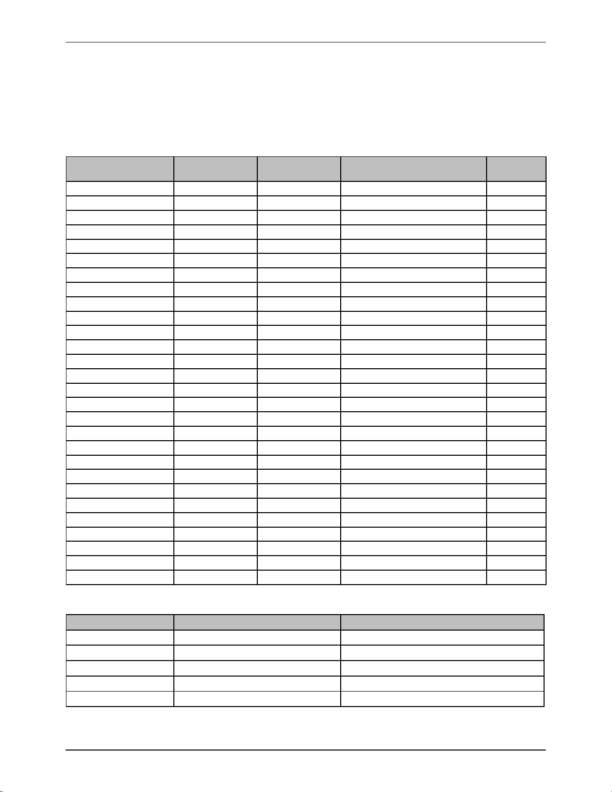
3. Refer to Table 1 with Figure 3 to complete wiring to the interface card.
Reconnect the wires of the 25 conductor cable and Table 2 to connect
internally to the iControl 2 for the “Conveyor Interlock”.
Table 1 iControl Discrete Input Cable Color Code Assignments
CABLE COLOR INPUT BOARD
TERMINAL FIELD TERMINAL
NUMBER FUNCTION NOTE
BLK 8 LO 1ZONE 1
WHT 9 LO 2ZONE 2
GRN 10 LO 3ZONE 3
ORG 11 LO 4ZONE 4
BLU 12 LO 5ZONE 5
WHT/BLK 13 LO 6ZONE 6
RED/BLK 14 LO 7ZONE 7
GRN/BLK 15 LO 8ZONE 8
ORG/BLK 20 LO 9PART ID bit 1
BLU/BLK 21 LO 10 PART ID bit 2
BLK/WHT 22 LO 11 PART ID bit 3
RED/WHT 23 LO 12 PART ID bit 4
GRN/WHT 0 LO 13 PART ID bit 5
BLU/WHT 1 LO 14 PART ID bit 6
BLK/RED 2 LO 15 PART ID bit 7
WHT/RED 3 LO 16 PART ID bit 8
ORG/RED 4 LO 17 TRIGGER BK 0
BLU/RED 5 LO 18 TRIGGER BK 1
RED/GRN 6 LO 19 TRIGGER SEL
ORG/GRN 7 LO 20 ENCODER A
−−−−−−−− N/C 21 −−−
−−−−−−−− N/C 22 −−−
−−−−−−−− N/C 23 −−−
RED 8 HI 24 +24 Vdc
BLK/WHT/RED −−− −−− −−−
WHT/BLK/RED −−− −−− −−−
RED/BLK/WHT −−− −−− −−−
GRN/BLK/WHT −−− −−− −−−
Table 2 iControl Conveyor Interlock Color Code Assignments
WIRE COLOR INPUT BOARD TERMINAL FUNCTION
WHITE 16 HI LOCKOUT
GREY 17 HI GUN PWR OK
VIOLET 18 HI MANUAL MODE
BROWN 19 HI CONVEYOR
BLACK 19 LO DCOM
iControl Opto-Input Interface Card Replacement
4
Part 1610834−02 E2018 Nordson Corporation
Installing New Interface Card (contd)
4. Use Figure 3 and 4 to configure jumpers and comb jumpers.
50 COND.
DIGITAL
I/O
RIBBON
CABLE
TO COMPUTER
25 CONDUCTOR
INPUTS 8 HI−15 HI INPUTS 20 HI−23 HI
INPUTS 16 LO−19 LO
INPUTS 0 HI−7 HI & GROUND
JUMPER JB16−19
JUMPER JA16−19
JUMPER JA8−15
JUMPER JB8−15 JUMPER JA20−23
JUMPER JB20−23
JUMPER JB0−7
JUMPER JA0−7
WIRES FROM iCONTROL
CONVEYOR INTERLOCK
JACKETED CABLE
(DETAIL 1) (DETAIL 3)
(DETAIL 4)
(DETAIL 2)
Figure 3 New Interface Card with Wiring and Ribbon Cable Connections
IN
IN NI
NININI
NININININININI
NI
NINI
NININININININIIN
NI
NI
NI
NI
NININININININIIN
ININININ
INININININININNI
JA19JA18
JA17
JA16
JA7JA6JA5JA4JA3JA2JA1JA0
JA8 JA9 JA10 JA11 JA12 JA13 JA14 JA15 JA20 JA21 JA22 JA23
JB0 JB1 JB2 JB3 JB4 JB5 JB6 JB7 JB16 JB17 JB18 JB19
JB23JB22JB21JB20
JB15JB14JB13JB12JB11JB10JB9JB8
DETAIL 2
DETAIL 1 DETAIL 3
DETAIL 4
Figure 4 Jumper Detail
Jumper Position Jumper Position
JA8 −JA15, JB8 −JB15 IJA20 −JA23, JB20 −JB23 I
JB0 −JB7, JA0 −JA7 IJB16 −JB19, JA16 −JA19 I
iControl Opto-Input Interface Card Replacement 5
Part 1610834−02
E2018 Nordson Corporation
Configure iControl 2 to Digital Interface Card
Verify the new iControl 2 is properly configured for the new digital interface
card, go to the Gun Configuration screen (see Figure 5) and select the
digital input card for PCLD782.
Figure 5 Gun Configuration Screen with Digital Input Card Selected
Parts
To order parts, call the Nordson Finishing Customer Support Center at
(800) 433-9319 or your local Nordson representative.
Part Description Quantity Note
1610832 KIT, 24 channel opto-input interface card, iControl 2 1
1107147 SCABLE, ribbon, 20 in, iControl 1
−−−−−−− SMODULE, 24 channel opto isolated DI 1
1107146 SJUMPER, com-style, 12 pole, 10 mm spacing 2
iControl Opto-Input Interface Card Replacement
6
Part 1610834−02 E2018 Nordson Corporation
Issued 01/18
Original copyright date 2018. iControl, Nordson, and the Nordson logo are registered trademarks of the Nordson Corporation.