Norelco safeCam TPA120 User manual

INSTRUCTION
MANUAL
PUBLIC ADDRESS AMPLIFIER
Montréal
2808 Rue J.A. Bombardier
Laval, QC H7P 6E4
Main Line: (450) 682-1511
Fax: (450) 682-1577
Toll Free: 1-800-361-7793
Calgary
1235- 64th Ave South East, Bay 10
Calgary, Alberta Canada T2H 2J7
Main Line: (403) 286-1234
Fax: (403) 247-0123
Toll Free:1-866-680-0123
Markham
450 Alden Road (Unit 1 & 2)
Markham, Ontario L3R 5H4
Main Line: (905) 752-1234
Fax: (905) 752-6000
Toll Free: 1-866-574-0123
Edmonton
10623 - 172 Street
Edmonton, Alberta T5S 1P1
Main Line: (780) 465-1234
Fax: (780) 490-1233
Toll Free: 1-877-701-0123
Toronto
27 Armthorpe Road
Brampton, Ontario L6T 5M4
Main Line: (905) 790-1234
Fax: (905) 790-1122
Toll Free: 1-800-668-3402
NOW MORE locations to serve you better !
www.norelcosafecam.com
TPA120
&
TPA240

THE FOLLOWING SYMBOLSARE USED ON THIS APPARATUS
Protective grounding terminal.
Alternating current/voltage
Hazardous live terminal
ON Denotes the apparatusturns on
OFF Denotes the apparatusturns off.
WARNING Describes precautions thatshould be observed to prevent the danger of injury
or death tothe user.
CAUTION Describes precautions that should be observed to prevent danger of the apparatus.
IMPORTANT SAFETY INSTRUCTIONS
Read these instructions.
Keep these instructions.
Heed all warnings..
Follow all instructions.
Do not usethis apparatus near water.
Clean only witha damp cloth.
Do not blockany of the ventilation openings.
Do not install hear any neat source such as radiator, heat registers, stoves, or other apparatus
that produce heat.
Toprevent the risk of fire or electrical shock, the apparatus shall not be exposed to dripping
moisture or splashing and that no objects filled with liquids, such as bases, shall be placed
on the apparatus.
Please read the notes proceeded by the symbol ! with the special attention, as they provide
important safety information.
These servicing instruction are for use by qualified personnel only. To reduce the risk of
electric shock do not perform any servicing other than that contained in the operating
instructions unless you are qualified to do so.
WARNING
The lightning flash with arrowed symbol within an equilateral triangle is intended to alert the
user to the presence of uninsulated "dangerous voltage" within the product's enclosure, that
may be of sufficient magnitude to constitute a risk of electric shock to persons.
The exclamation point within an equilateral triangle is intended to alert the user to he presence
of important operating and maintenance (servicing) instructions in the literature accompanying
the appliance.
Do not blockany of the ventilation openings. The apparatusshould be placed ona solid
surface with aminimum distance of 1m from the back or side topplate to the wall and
not
in the following environments of cases:
Moist place;
Under direct radiationof sunlight or other strong heat radiation;
No air ventilation.
CAUTION
RISK OF ELECTRIC SHOCK
DO NOT OPEN
CAUTION : SHOCK HAZARD - DO NOT OPEN
RISK OF FIRE-REPLACE FUSE AS MARKED.
1
Additional outputs / voltage-impedance
Tone controls
Controls
PREAMP OUT / mono RCA jack / 1V-600 / unbalanced
Loudspeaker / on terminal board / 1 watt-8
Bass 10dB-100Hz
Treble 10dB-10KHz
7 volume controls for INPUT 1-4,AUX IN, 1W 8 and Tel.Paging.
5 zone paging select switch
1 bass control
1 treble control
1 master volume control
Power supply / Consumption
115/230 Vac ( 5%)-60/50Hz 480W (240W series)
115/230 Vac ( 5%)-60 50Hz 360W/ (180W series)
115/230 Vac ( 5%)-60/50Hz 240W (120W series)
115/230 Vac ( 5%)-60 50Hz 120W/ (60W series)
435mm 335mm 100mm
Dimensions(L )WH
EXAMPLE OF POSSIBLE CONNECTIONS
Use only with a 250V fuse
-
+Tel Paging
8
T R G
Priority
1W
Z4 Z3 Z2 Z1
COM
100V70V25V
4 8 16
COM
GND
R
L
1: for CD
2: for Tuner
3: for Tape
4: for AUX IN
1 2 3 4
PRE
OUT
MAIN
IN
CAUTION:
ELECTRIC SHOCK HAZARD
DO NOT REMOVE COVER.
REFER SERVICING TO
QUALIFIED PERSONNEL.
SEE INSTRUCTION MANUAL.
INPUT 1 INPUT 2 INPUT 3 INPUT 4
UNBALANCED
Monitor
VOL.
TEL.
VOL.
Equalizer
Speaker Horn speaker
Microphone
Microphone stand
Mains
CD player
Power amplifier
Sound column
Contact
"VOICE PRIORITY"
Speaker
Aux.signal
AM/FM tuner
CD player
Cassette player
AM/FM tuner
Cassette recorder
10
Outputs for speakers / Volts
Outputs for speakers / Ohms
Do not defeat the safety purpose of the grounding-type plug. Agrounding type plug has two blades
and a third grounding prong. The third prong are provided for your safety. When the provided
plug does not fit Into your outlet, consult an electrician for replacement of the obsolete outlet.
Protect the power cord from being walked on or pinched particularly at plugs, convenience
receptacles, and the point where they exit from the apparatus.
Only use attachments/accessories specified by the manufacturer.
Unplug this apparatus during lightning storms or when unused for long periods of time.
Refer all servicing to qualified service personnel. Servicing is required when the apparatus has
been damaged in any way,such as power-supply cord or plug is damaged, liquid has been spilled
or objects have to rain or moisture,fallen into the apparatus, the apparatus has been exposed
does not operate normally, or has been dropped.
This handbook is an integral part of the product and must accompany it when changing owner,
to allow the new owner to get to know the installation, operating, and safety instructions.
Safety precautions
The following general safety precautions must be observed during all phases of operation, service
and repair of this apparatus. If this apparatus is used in a manner not specified in this manual,
the protection provided by this apparatus may be impaired. Also, our corporation assumes
no liability
for the customer's failure to comply with these requirement.
Power Supply
Ensure the source voltage matches the voltage of the power supply before turning ON the power.
Power Cord and Plug
To prevent an electric shock or fire ,be sure to use the power cord supplied by our corporation.
The main power plug must be plugged in an outlet with protective grounding terminal. Do not
invalidate protection by using an extension cord without protective grounding.
You shall hold the plug firmly to avoid the pull-out of power cord and risk occurring when you pull
the power cord out from AC outlet .
If the apparatus is not to be used for long periods of time .turn it off and disconnect the power
supply cord.
Precaution
Toprevent a fire, make sure touse fuses with specified standard (current, voltage, type)
Before replacing the fuse, turn OFF the power and disconnect the power source. Do not use a
different
fuse or short-circuit the fuse holder.
Cleaning
When the apparatus needs a cleaning, you can blow off dust from the apparatus with a blower
of clean with rag etc. Don't use solvents such a benzol, alcohol, or other fluids with very strong
volatility and flammability for cleaning the apparatus body.
Other
If the apparatus givesoff any strangesmoke switch it off immediately and disconnectthe
power from the supply cable.
Do not obstruct the ventilation grilles of the apparatus.
Avoid having the apparatus work on overload for a long time.
Do not force command parts (buttons, controls, etc.)
If connecting interference takes place in source circuit, THD will be more than 10%.
Description
The amplifiers in the series have been expressly designed for transmitting announcements
through all PA sound systems. They incorporate the following functions:
4 combination jack (XLR and 6.3mm) inputs, line/micro switchable sensitivity with
excusable 24Vdc phantom supply.
2
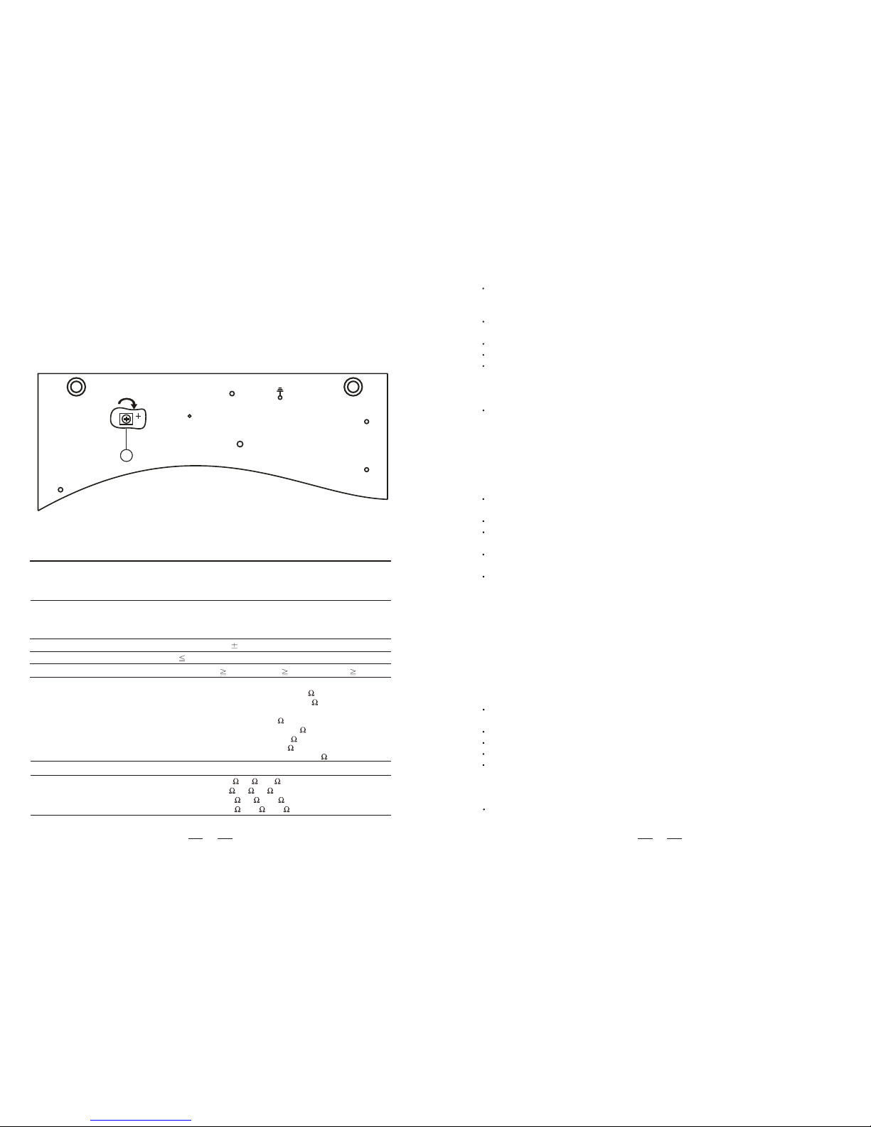
1) Unscrew the 4 screws on each side and2 screws top on side ofthe amplifier and take
off the cover.
2) Inside the amplifier, find the hole "F"on the INPUT CARD which permits acting on the
trimmer "VR 103" on the cardbeneath.
3) Using a small screwdriver, adjust the trimmer "VR 103":by turning the control clockwise the
sensitivity increases, andthe priority function will be a less intense voice signal.
4) Fit thebottom back onto the amplifier.
VR 103
FF
Technical data
Amplifier section
Type
Signnal / noise ratio
Inputs / sensitivity-impedance
Output power capacity
Frequency response
Total harmonic distortion
25V-70V-100V (10 , 83 , 170 )
25V-70V-100V (3.5 , 27 , 55.6 )
(SA,SAB 2060)
25V-70V-100V (5 , 42 , 83 ) (SA,SAB 2120)
(SA,SAB 2180)
25V-70V-100V (2.6 , 20.5 , 41.7 ) (SA,SAB 2240)
4ohms 8ohms 16ohms
60W-Mono-tabletop (60W series)
120W-Mono-tabletop (120W series)
180W-Mono-tabletop (180W series)
240W-Mono-tabletop (240W series)
AUX IN: 70dB MAIN IN: 80dBINPUT 1-4: 60dB
MAIN IN / mono R A jack / 0dB(1V)-10K / unbalancedC
ATPE:-15dB (200mV)-20K
TUNER : -10dB (300mV)-56K
CD: -5dB (570mV)-80K
AUX IN / stereo RCA jack / unbalanced
Line: -25/-20dB (50/100mV)-47K , bal./unbal.
Mic: -55/-52dB (2.3/2.7mV)-600 , bal./unbal.
INPUT 1-4 / XLR and 6.3mm combination socket :bal./ unbal.
Nominal: 60W- maximum:90W
Nominal: 120W- maximum:150W
Nominal: 180W- maximum:240W
Nominal: 240W- maximum:300W
30-30,000Hz ( 3dB)
0.5%(1KHz-nominal power capacity)
AUX1:-20dB(100mV)-20K
9
0 0 0 0 0 0
10 10 10 10 10 10
INPUT1INPUT2INPUT3INPUT4
INPUT5
MASTER
_10 +10
BASS
_10 +10
TREBLE
Z1 Z2 Z3
PAGING SELECT
PORT SIGNAL PEAK
Z4 ALL
POWER
OUTPUT
P.L
Public Address Amplifier
OFFON
CHIME
1
2
3
86 57
9
10
11 13
4
12
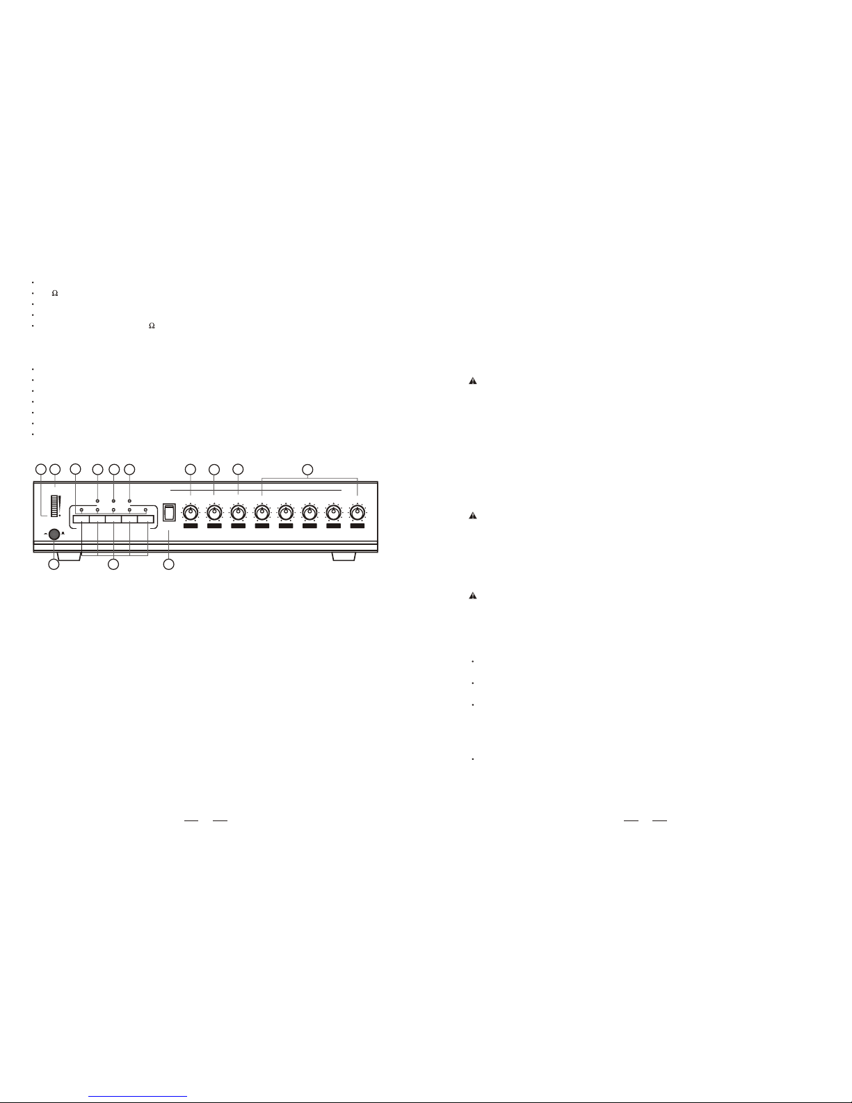
CONTROL ANDFUNCTIONS
1. Input levelcontrol
These controls let you individually set the volume of the sound source that are connected
to the "INPUT "INPUT 2", "INPUT 3","INPUT 4", "INPUT 5" Turning a control clockwise1",
increases the volume of corresponding source. We recommend to leave the control ofthe
momentarily not used inputs attheir minimal setting"0".
2. Common BASS-control
When turned clockwise this control enhances the low frequency reproduction, while turning
it counter-clockwise attenuates the bass frequencies. If the control is set to its center
position, the overallfrequency response is notbeing altered.
3. Common TREBLE-control
When turned clockwise this control enhances the high frequency reproduction, while turning
it counter-clockwise attenuates the treble frequencies. If the control is set to its center
position, the overallfrequency response is not being altered.
4. MASTER volumecontrol
The setting of this control determines the output level that is present at the loudspeaker
OUTPUT.We recommend togenerally adjust the MASTERand the input level controls at
mediocre positions.
Extreme setting, where the MASTER is set to maximum output and the input controls nearly
set to theirminimum or vice versa are not recommendable.
5. Peak indicatedlight.
1 stereo RCA input, three stage sensitivity selectable.
600 teliliary signal(Tel. Paging) input.
1 "PREAMP OUT" output.
1 "MAIN IN" input
1 "MONITOR OUTPUT 1W/8 " slave output for monitor music signal.
Input 1 priority on the other inputs with vocal activation.
Input 1 priority on the other inputs, activation with contact.
Outputs for speakers with constant impedance (4-8-16 ohm) and constant voltage (25-70-100 V).
Treble and bass controls.
VU-meter with LEDs.
Protection against short-circuiting between output terminals.
Option zone paging selectable function, four zone paging and all zone paging.
A singal indicated light(the light on as the signal in put).
A peak indicated light (the light on as the pack input).
A output-prot indicated light (output auto break downed as the light on)
FRONT PANEL
3
Before using the amplifier for the first time, make sure that the appliance's voltage is in
accordance to your supply.mains
Connect the amplifier only to grounded mains outlets. Connecting the amplifier to the mains
supply(115/ has to beaccomplished by inserting the supplied mains cord into the230Vac)
corresponding socket (11) and afterward plugging it into a mains outlet.
CONNECTING THE OUTPUT TERMINALS
8
We strongly recommend that you leave the connection of the appliance to the qualified and
experienced
service technician who is specialized in connecting electrical and electronic equipment.
Do not take the risk of Electro-shock or shock hazard. To reduce the risk of Electro-shock,
all connections have to beaccomplished before it is permissible toconnect the amplifier
to the main supply, Before connecting the appliance to the mains supply, once again make
certain that all connections are carried out correctly and that no short-circuit exist. The
overall sound reinforcement installationhas to be in accordance to the laws, requlations,
standards, and guidelines that are relevant and applicable in the country where the equipment
is going tobe operated.
INSTALLATION
See INSTALLATION 1 & INSTALLATION 2.
INSTALLATION NOTES
At all times, theamplifier has to beoperated under appropriate conditions. This includes
that the operation location provided sufficient ventilation and the device isnot exposed to
direct sunlight or the direct radiation or reflection from any heat source. Installing the
loudspeaker systems choose a location that gets not affected by extreme and / or constant
vibration or other mechanical oscillation. Also make sure that thespeakers are installed
at locations thatare free from dust and / or moisture.
CAUTION
CAUTION
AC POWER SUPPLY
Toavoid the risk of electrical shock, never touch the bare conductors leading to the output
terminals of the amplifierwhen it is in operation. Under figures(see 16.Outputterminal in
CONTROLS AND FUNCTIONS), show the possible connections of the "OUTPUT" speaker
terminals accessible by removing theprotective oc ver. Bear in mind the following rules:
Constant impedance lines
The total impedance of the speakers connected must correspond to that selected on
the amplifier's output terminals.
The sum of the power capacities of the speakers must be no lower than the amplifier's
power capacity.
The length of the connecting cables must be as possible; in any case, the longer the
distance to becovered and the greater must be the cross-section of the cables.
Constant voltage lines
Each speaker must be equipped with a line transformer with an input voltage equal to that
of the line (25,70, 100V).
The sum of the power capacities of the speakers must not exceed the output power
capacity of the amplifier (i.e. total wattage of speakers installed in zones 1 through 4).
Adjusting sensitivity for the "voicepriority" function
Tochange the level of the signal determining activation of the"Voice Priority"fu ction,n
proceed as follows:
CAUTION
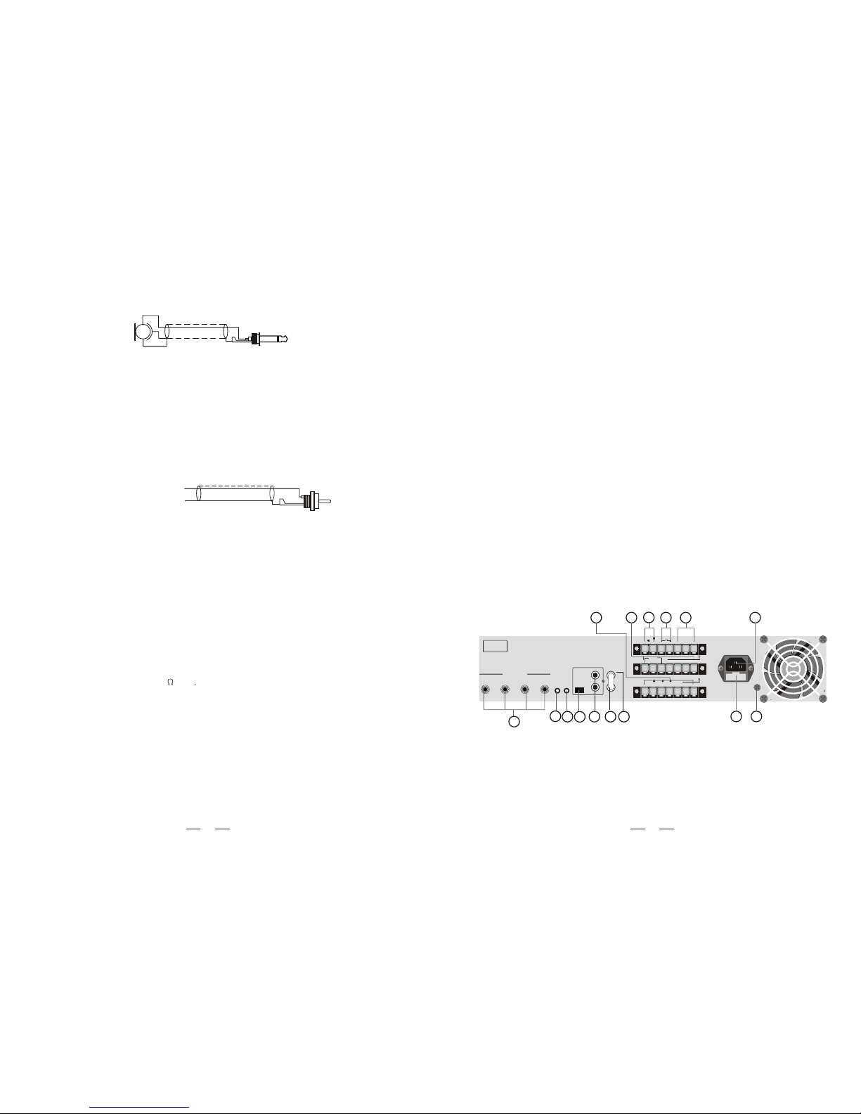
REAR PANEL
Use only with a 250V fuse
-
+Tel Paging
8
T R G
Priority
1W
Z4 Z3 Z2 Z1
COM
100V70V25V
4 8 16
COM
GND
R
L
1: for CD
2: for Tuner
3: for Tape
4: for AUX IN
1 2 3 4
PRE
OUT
MAIN
IN
CAUTION:
ELECTRIC SHOCK HAZARD
DO NOT REMOVE COVER.
REFER SERVICING TO
QUALIFIED PERSONNEL.
SEE INSTRUCTION MANUAL.
INPUT 1 INPUT 2 INPUT 3 INPUT 4
UNBALANCED
Monitor
VOL.
TEL.
VOL.
141516
28
27
26
25 24
23
22
21
20
17
18
19
6. Signal indicatedlight.
7. Output-port indicatedlight (output auto break downed as the light on)
8. Zone pagingbroadcast indicate LED
When the LED lightingit indicate zone pagingselect is working status,oppose that when
the LED off indicate zone paging select is off.
9. LED VU-meterinstruments
This instrument shows the signal's output level. For proper operation of the amplifier correct
volume setting ofmajor importance. The first eightLED-segments on thedown represent
the area between-20dB and 0dB, in which the outputted level shouldbe kept. In case the
last two segments on the up are lit for a longer period of time, this means that the outgoing
signal is driven into clipping, which mostly results in audible distortion. You have to adjust
the volume ata lower setting.
10. Indicator
When switching the amplifier's power on, the "PL" indicator lights. When the amplifier's
output overload, the "OVER LOAD" indicator lights and interrupt output. For equipment
life, you haveto adjust the volume at a lower setting.
11. "POWER"switch
Using the POWER switch lets you turn the main power on or off. The power is on when the
switch is onits "ON" position, and it off when the switch is on its "OFF" position.
12. Zone pagingselect switch
Speaker lines of each zone can be connected or disconnected independently "Z1~Z4". To
connect the speaker lines, turn the switch on. To disconnect the speaker lines, turn the
switch off. Turn the "ALL" switch on allows announcement to the entire zone regardless of
the setting ofthe individual zone selection switch can be operated.
13. CHIME switch
Chime is OFF when the CHIME switch at the middle position, as it is at working status
when the switch at downside, andwhen push the switch toupside then produce a chime.
When chime is working, it has priority function it's volume is controlled by INPUT1 and
MASTER.
4
CONTROL ANDFUNCTION
14. Main cordconnector
This connector ismeant for the connection of the supplied mains cord.
15. Input "Tel. paging"
The terminals input lets you connect to a telephone signal (600 ohms). The input features the
"Voice Priority" function, which overrides all other input signals once, messagea telephone
is sent. If you want to have this function disabled forever, please contact a SHOW SERVICE
CENTER.
"Input 1" has a "Voice Priority" function that excludes all the other inputs as soon as a
message is transmitted with a microphone; it is possible to exclude this function by calling
a SHOW SERVICE CENTER.
21. Input sensitivityswitch (AUX IN)
By turning these switch onto the "CD" position the "AUX IN" input suitable for connected to
CD player signal output.By turning these switchonto the "TUNER" positionthe "AUX IN"
input suitable for connected to AM/FM radio signal output. By turning these switch onto the
"TAPE" position the "AUX IN" input suitable for connected to desktop cassette player signal
output.
22. "AUX IN"inputs
The "R" and "L" sockets permit input of the right ("R")and left ("L") channels of an audio source
with a , such as an AM/FM tuner, a cassette deck, a CD player, etc..high-level output signal
Use input sensitivity suitable for difference appliances.They are able to takeswitch (19),
RCA-type coaxial connectors,and unbalanced signals.
Unbalanced microphone Mono jack
Unbalanced signal (channel L or R)
Earth
RCA plug
23. "MAIN IN"terminal
After removing the bridging-strip between the "PRE OUT" and the "MAIN IN" terminals you
can include an external signal processor (e.g. an equalizer) in the audio-chain between the
pre-amplifier and the power output stage of the power amplifier. This opportunity provides
a proper solutionwhenever shaping or improving the audio signal is necessary(adjusting
delay times, equalizing, eliminating the Larsen-effect, etc.). The input is unbalanced, which
affected by the tone controlsand the master volume control.
24. "PREAMP OUT" terminal
This terminal output the mixed audio signals of all sources that are connected to the amplifier's
inputs and can beutilized to feed anexternal power amplifier,a signal processor (e.g.an
equalizer), or any other external appliance. The unbalanced signal is affected by the individual
input controls. Before using the PREAMP OUT you have to remove the bridging-strip between
this binding postand the "MAIN IN" terminal (21).
25. Music signalmonitor output level control
The control lets you individually set the volume of the sound source output that is connected
to the "MONITOR OUTPUT1W/8 "(14) Turning controls clockwise increases the volume
of the correspondingsource.
26. Tel. Paging input level control
This control lets you set the volume of the sound source that is connected to the "Tel. Paging"
(12). Turning control clockwise increases the volume of the corresponding source. We
recommend to leave the control of momentarily not used input at their minimal setting "0".
27. AC fuse
The fuse protects the alternating currents supply circuit of the equipment. The fuse can only
be changed inthe event of a fault.
28. "GND" screw
In case the used mains outletdoes not provide a ground conductor, thisscrew offers the
possibility to ground the amplifiers metal parts. Nevertheless, you should leave this procedure
to the experienced,qualified electrician.
7

Auxiliary conctat
Tel. paging
-
+T
8
RG
Priority
1W
18. Zone outputterminal
This output terminal connects to the speaker lines. Total speaker wattage is up to nominal
power for zones 1-4. When using a zone selector low-impedance speakers cannot be
used, default is constant voltage 100V output.
Connecting the speakers to 100V output
0 100V 0 100V 0 100V 0 100V
Z4 Z3 Z2 Z1
COM
19. Output terminals
These 5 terminalsallow connecting speakers.
Connecting the speakers to 4 ohm output
+
4 ohm
100V70V25V
4 8 16
COM
Total impedance 4 ohm
8 ohm 8 ohm
--
++
--
++
100V70V25V
4 8 16
COM
Connecting the speakers to 25V output
0 25V 0 25V 0 25V
100V70V25V
4 8 16
COM
Connecting the speakers to 70V output
0 70V 0 70V 0 70V
100V70V25V
4 8 16
COM
Connecting the speakers to 100V output
0 100V 0 100V 0 100V
100V70V25V
4 8 16
COM
20. "INPUT 1","INPUT 2", "INPUT 3"and "INPUT 4" Inputs
These four unbalanced combination type jack 6.3mm inputs, dynamic microphone (30-600
ohms)or a highlevel sound source (e.g. AM/FM tuner, cassettedesk, CD player, etc.).
16. "Priority" terminal
When short-circuiting these terminals (i.e. by means of using an electrical switch), the audio
signals coming from "AUX IN",are attenuated while the signals comingfrom "IN2", "IN3"
and "IN4" are gaining priority.
17. Output terminalfor auxiliary loudspeaker
The terminal is meantfor the connection ofa small external loudspeaker thatgets driven
by an internal auxiliary power amplifier,providing a nominal output 1 watt. Onlythe mixed
audio signal coming from "AUX IN" are included in the outputted signal. In addition,the
output signal is controlled only by the volume control of the "AUX IN", music signal level
control (23).
-
1 8 ohmW
+
Tel. paging
-
+T
8
RG
Priority
1W
5 6
This manual suits for next models
1
Table of contents


