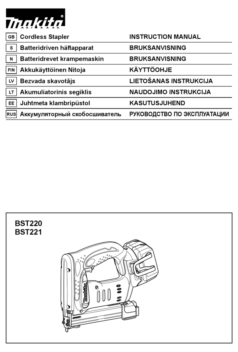
Norge 10023321 User manual

OPERATING INSTRUCTIONS
18G FlOORING STAPLER
MODEL: 10023321
6
PARTS LIST
Refer to the Exploded View Drawing for the location of parts listed below
DESCRIPTION
WASHER
TRIGGERASSEMBLY
TRIGGERPIN
SCREW M4*16
WASHER
OBLIQUEBLOCK
SCREW M4*25
DRIVEGUIDE
LIMITEDBLICK
SLIDEPLATE
BUSHING
SCREW
DRIVEGUIDE
SPRING PIN 2.5*12
MOVABLEMAGAZINE
FEEDERSHOE
SPRING
FIXEDMAGAZING
NUTM4
MAGAZINGPLATE
SCREW M4*6
SCREW M4*14
SPRINGPIN
SPRING
LOCK
JIONTGUIDE
WASHER
STOPPEDSCREW
SUPPORT
NUT
SCREW
SOFTGRIPSLEEVE
GASKET
ENDCAP
WASHER4
AIRPLUG
1
2
3
4
5
6
7
8
8a
9
10
11
12
13
14
15
16
17
18
19
20
21
22
23
24
25
26
27
28
29
30
31
32
33
34
35
36
ITEM
37
38
39
40
41
42
43
44
45
46
47
48
49
50
51
52
53
54
55
56
57
58
59
60
61
62
63
64
65
66
67
68
69
70
71
72
DESCRIPTION
SCREWM4*10
BUSHING
EXHAUSTCOVER
WASHER
SCREW M5*20
SPRINGWASHER 5
CYLINDERCAP
GASKET
SPRING
VALVESEAT
O-RING 15.7*2
O-RING 38.8*3
VALVE
O-RING 33.5*3.5
STOPPEDWASHER
COLLAR
O-RING 50.5*2.5
O-RING28.3*3
PISTONASSEMBLY
CYLINDER
O-RING 36.3*2.5
O-RING 35.3*2.5
BUMPER
BODY
JOINTGUIDE
SAFEGUIDE
SPRING
SAFEBRACKET
SPRING PIN3*26
SEAL
TRIGGERVALVEHEAD
O-RING 15*1.9
TRIGGERVALVEGUIDE
O-RING 5.5*1.5
SPRING
TRIGGERVALVESTEM
SPRING
ITEM
PDF !"# "pdfFactory Pro" $#%&'( www.fineprint.cn

5
EXPLODEDVIEWDRAWING
CONTENTS
SUMMARY
SPECIFICATIONS
SAFETYWARNINGS&CAUTIONS
UNPACKING
SETTING
CONNECTINGTHETOOLTOANAIRSUPPLY
LOADINGTHEFASTENERS
OPERATINGTHETOOL
REGULARMAINTENANCE
TROUBLESHOOTING
EXPLODEDVIEWDRAWING
PARTSLIST
1
1
1
2
2
3
3
3
3
4
5
6
PDF 件使用 "pdfFactory Pro" 试用版本创建 www.fineprint.cn

Characteristic
MinimumOperatingAirPressure
MaximumOperatingAirPressure
StaplerLengthRange
StaplerSize
StaplerCapacity
AirInlet
AirConsumption
ToolWeight
Value
60 PSI
100 PSI
3/8"-- 1/4"
18Gauge
100
1/4"NPT
3.8CFM
3.59lbs
1
SPECIFICATIONS
SUMMARY
Youwill needtheinstructionsforthesafetywarningandcautions,assemblyinstructions,operatingandmaintain-
ingprocedures,explodedviewdrawingandpartslist.Keepyourinvoice withtheseinstructions.Keeptheinstruc-
tionsandinvoiceinasafeanddryplace forfuturereference.
READALLINSTRUCTIONSBEFOREOPERATINGTHETOOL
1.Lubricateasinstructed.
2.Checkairsupply.
3.Replacespring.
4. Replace damagedinternal
parts.
1.Replacejointguider.
2. Usetherecommendedand
undamagedfastenerls.
3.Tightenscrews.
4.Replace piston assembly.
1.Replace piston assembly.
2.Adjusttoadequateair
pressure.
3. Checkcylindercapspring for
brokencoilsorreducedlength.
Checkifexhaustportofcylin-
dercapisrestricted.
1.Replace bumperorpusher
spring.
2.Cleandrive channeloffront
plate.
3. Checkhose andcompressor
fittings.
4.Replace O-ring orlubricate.
5.Replace seal.
4
TROUBLESHOOTING
PROBLEM
Airleaking at
Triggerarea
PROBLEMCAUSE SOLUTION
1.O-ringintriggervalveisdamaged.
2.Triggervalveheadisdamaged.
3.Triggervalvestem,sealorO-ringisdam-
aged.
1.Checkandreplace O-ring.
2.Checkandreplace trigger
valve head.
3.Checkandreplace trigger
valvestem, sealorO-ring.
Airleaking between
bodyanddriveguider Damagedbumper.
Airleaking between
bodyandcylindercap 1. Screwloose.
2.Damagedgasket. 1.Tightenscrews.
2.Checkand replace gasket.
Bladedrivingfastener
toodeeply 1.Wornbumper.
2.Airpressure istoo high. 1.Replace bumper.
2.Adjustthe airpressure.
Checkand replace bumper.
Runsslowlyorhas
powerloss
Toolskipsa fastener
Fastenersarejammed
Toolwillnotdrive
downtight
1.Insufficientoil.
2.Insufficientairsupply.
3.Brokenspring incylindercap.
4.Exhaustportincylindercapisblocked.
1.Wornbumperordamagedspring (53).
2. Dirtindriveguider.
3.Inadequateairflowtotool.
4.WornordryO-ring onpiston.
5. Cylindercapsealleaking.
1.Jointguiderisworn.
2. Fastenersare wrong size ordamaged.
3. Magazine orfrontplate screwsare loose.
4.Bladeinpiston assemblyisdamaged.
1.Wornblade inpiston assembly.
2. Lackofpower.
3.Slowcycling andloss ofpower.
STOPUSINGTHETOOLIMMEDIATELYIFANY OFTHEFOLLOWINGPROBLEMS
OCCUR. SERIOUSPERSONALINJURYCOULDOCCUR.ANYREPAIRSORREPLACE-
MENTSMUSTBEDONEBYAQUALIFIEDPERSONORAN AUTHORIZEDSERVICECENTER
ONLY.
SAFETYWARNINGS&CAUTIONS
1. KEEPWORKINGAREACLEAN. Clutteredareasinviteinjuries.
2. DON TALLOWCHILDRENATTHEWORKINGAREA. Don t letthem handlethetool.
3. DONOTOPERATETHISTOOLIFUNDERTHEINFLUENCEOFALCOHOLORDRUGS. Read
warninglabelonprescriptionstodetermineifyourjudgmentorreflexesareimpairedwhiletakingdrugs.Ifthere
isanydoubt, do notattempttooperate.
4. USESAFETYGLASSES. SafetyglassesshouldconformtoANSIZ87.1specifications. Beforeoperating,
wearsafetyglassesagainst flyingdebrisfromthefront andside.Safetyglassesshouldbewornwhenloading,
operating,unloadingorservicingthistool.
5. USEEARPROTECTION. Theworkingarea maybeexposedtohigh noiselevelsthatcanleadtohearing
damage.
6. NEVERUSEOXYGENCOMBUSTIBLEGASES, BOTTLEDGASESORHIGHPRESSURE
COMPRESSEDGASASAPOWERSOURCEFORTHISTOOL. Thetoolmayexplodeand cause
seriousinjury.
7. DRESS SAFELY. Protectiveglovesand nonskidfootwearorsafetyshoesarerecommendedwhenworking
withand operatingthistool. Don twearlooseclothing orjewelry.Theycangetcaughtinmovingparts.Also,
wearaprotectivehaircoveringtopreventlonghairfromgettingcaughtinthetool.
8. DONOTFIREINTOHARDMATERIALS. Donotattempttoshoot towardhardorbrittlematerialsuch
asconcrete,steel ortile.
9. WHENOPERATINGTOOL. keeptheproperfootingand balancetoavoiddamageresulting fromlosing
balance.
10.CHECKDAMAGEDPARTS. Beforeusingtool, carefullycheckifthereisany part damaged.
11.REPLACEPARTSANDACCESSORIES.Onlyallowtheuseofthesamereplacementpartswhileservicing.
Approvedaccessoriesandreplacementpartsareavailable.
12.KEEPALERT. Watchwhatyouaredoing.Usecommon sense. Donotoperateany toolwhenyouaretired.
PDF 件使用 "pdfFactory Pro" 试用版本创建 www.fineprint.cn

CONNECTING THE TOOL TO AN AIR SUPPLY
1. Determine if the tool needs oil and, if necessary, place two drops of oil in
the AIR PLUG(72) as shown in Figure 2. If you are using an automatic in-line
oiler, check and add oil if necessary.
2. Turn the compressor on and set the regulator to the proper pressure for the
size and type of fastener being used.
3. Connect the tool to the air supply (see Setup for air supply connection
recommendations).
Figure 2
Figure 3
LOADING THE FASTENERS
1. Depress the LOC K(60) to release the MOVABLE
MAGAZINE (51) and pull the magazine out fully as shown
in Figure 3.
2. Place a full clip of the specified type and size fasteners on
the FIXED MAGAZINE (54), up to 100 fasteners may be
loaded in the magazine.
3. Push the MOVABLE MAGAZINE ASSEMBLY forward
until it is locked.
OPERATING THE TOOL
Test the driving depth in a sample piece of wood before using. If the fasteners are being driven too far or not far
enough, adjust the regulator to provide less air pressure or more air pressure.
1. Connect the tool to the air supply. Make sure the air pressure is in correct range denoted in section of
SPECIFICATIONS.
2. Load fastener as above the direction given in the section called LOAD THE FASTENER.
3. Hold the Body (23) and press the Drive guide (44) to work surface , be sure the tool is straight and then gently
depress the Trigger (38) to drive the fastener.
4. Lift the tool off the work surface.
3
REGULAR MAINTENANCE
1. Frequent, but not excessive, lubrication is required for best performance. Oil added through the airline connection
will lubricate internal parts. An automatic airline oilier is recommended but oil may be added manually before every
operation or after about 1 hour of continuous use. Only a few drops of oil at a time are necessary. Too much oil will
collect inside the tool and be blown out during the exhaust cycle. ONLY USE PNEUMATIC TOOL OIL. Do not
use detergent oil or additives, as these lubricants will cause accelerated wear to the seal in the tool.
2. Use a small amount of oil on all moving surface and pivots.
3. Dirt and water in the air supply are major causes of pneumatic tool wear. Use a filter/oiler for better perfor-
mance and longer life. The filter must have adequate flow capacity for the specific application. Consult the
manufacturer's instructions for proper maintenance of your filter.
4. Keep tools clean for better and safer performance. Use nonflammable cleaning solutions ( CAUTION: Such
solutions may damage O-ring and other tool parts)only if necessary- DO NOT SOAK.
Description
Stapler
S3 Hex Key
S4 Hex Key
Air Tool Oil
Teflon Tape
Operatinginstruction
Qty
1
1
1
1
1
1
2
Figure 1
SETTING
Your air tool is fully assembled when you receive it. Before using it, attach the air line and desired air system
accessories. See Figure 1 for the recommended accessories and connection order. Be sure the air hose is depressur-
ized when installing or removing adapters to the air line.
WARNING: The warning, caution, and instructions explained in this instruction manual cannot cover
all possible conditions and situations that may occur. It must be understood by the operator that COM-
MON SENSE AND CAUTION ARE FACTORS WHICH CANNOT BE BUILT INTO THIS
PRODUCT, BUT MUST BE SUPPLIED BY THE OPERATOR.
UNPACKING
When unpacking, check and make sure that all the accessories are included. If anyone is missed or broken,
please call seller for help. Refer to the follow lists.
13. STORE THE TOOL. When not in use, tool should be cleaned, fully assembled and then, stored in a dry
location to reduce rust. For safety, keep out of reach of children.
14. OUTDOOR EXTENSION CORDS. When air compressor is used outdoors, use only rounded jacket ex-
tension cords intended for outside use. See manufacturer’s manual for the AWG required for the compressor’s
amperage draw.
15. PAY ATTENTION TOAIR HOSE AND THEIR CONNECTIONS. Don’t trip over hoses. Make sure all
connections are tight.
16. AFTER LOADING THE FASTENERS. never point the tool at yourself or bystanders.
17. USE THE CORRECT AIR CONNECTOR. The connector onthe tool must not hold pressurewhen the air
supply isdisconnected. If thewrong fitting is used, the tool can be charged with air after being disconnected and
still be able to drive a fastener.
18. WHEN CONNECTING THE AIR. The tool may possibly fire the fasteners as soon as you plug it in to air
hose. Therefore, remove all the fasteners before connecting to the air.
19. DO NOT DEPRESS THE TRIGGER WHEN LOADING.
20. IF THE FASTENERS ARE JAMMED. Disconnect the tool from the air and remove the jammed fasteners.
STAPLER
QUICK
CONNECTOR OILER
REGULATOR
AIR HOSE
AIR SUPP LY
PDF !"# "pdfFactory Pro" $#%&'( www.fineprint.cn
Table of contents

