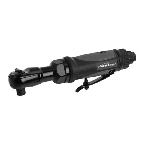
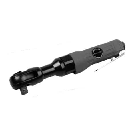
Neilsen CT1082 User manual

1/4
" DRIVE AIR RATCHET WRENCH CT
ORIGINAL INSTRUCTIONS
SAVE THESE
INSTRUCTIONS AND PRECAUTIONS.
READ ALL PRECAUTONS AND INSTRUCTIONS BEFORE USE.
Cannon Tools Limited
Address:
20 Station Road, Rowley Regis, West Midlands, B65 0JU.U.K.
" DRIVE AIR RATCHET WRENCH CT
1082
INSTRUCTIONS AND PRECAUTIONS.
READ ALL PRECAUTONS AND INSTRUCTIONS BEFORE USE.
20 Station Road, Rowley Regis, West Midlands, B65 0JU.U.K.

2
EC DECLARATION OF CONFORMITY
We CANNON TOOLS LTD
20 Station road, Rowley Regis, West Midlands,B65 0JU.U.K.
Declare that the following machine complies with the appropriate basic safety and
health requirements of the EC Directive based on its design and type, as brought
into circulation by us.
In case of alteration of the machine, not agreed upon by us, this declaration will
lose its validity.
Product description: 1/4" DRIVE AIR RATCHET WRENCH
Model: CT1082
Applicable EC Directives:
EC Machinery Directive 2006/42/EC
Harmonized standards
EN ISO 11148-6
20 Station Road, Rowley Regis, West Midlands, B65 0JU.U.K.
Mr. Gurcharan Tony Singh Sanghera
Managing Director
CANNON TOOLS LTD
2016-09-18

3
Fig. A: Product components:
AIR RATCHET WRENCH
1. APPLICATION
The air ratchet wrench is a pneumatic portable tool, used for running small bolts in tight space.
Designed for body shop works,
radiator, spark plug , air condition & water pump works. It is not
designed for commercial or industrial use.
WARNING! Read this manual and general safety instructions carefully before using
the appliance, for your own safety. Your power tool should only
with these instructions.
2. DESCRIPTION (FIG A)
1. Ratchet anvil 1/4”
2. Trigger
3. Reverse bottom
4. Air inlet (Europe style coupler)
The air ratchet wrench is a pneumatic portable tool, used for running small bolts in tight space.
radiator, spark plug , air condition & water pump works. It is not
WARNING! Read this manual and general safety instructions carefully before using
the appliance, for your own safety. Your power tool should only
be passed on together

4
3. SAFETY WARNINGS
SYMBOLS
In this manual and/or on the machine the following symbols are used:
Follow all workshop safety rules, regulations, and conditions when usingwrench.
Do not wear watches, rings, bracelets or loose clothing when using airtools.
WARNING! Disconnect from air supply before changing accessories orservicing.
Maintain the wrench in good condition and replace any damaged or worn parts.
Use genuine parts only. Non-authorized parts may bedangerous.
WARNING! Check correct air pressure is maintained and not exceeded. We
recommend 90psi.
Keep air hose away from heat, oil and sharp edges. Check air hose for wear
before each use and ensure that all connections aresecure.
Only use sockets which are specifically designed for use with a ratchet wrench.
Wear approved safety eye/face shield, ear defenders, and hand protection.
WARNING! Due to the possible presence of asbestos dust from brake linings,
when working around vehicle brake systems we recommend you wear suitable
respiratory protection.
Maintain correct balance and footing. Ensure the floor is not slippery and wear
non-slip shoes.
Keep children and non essential persons away from the workingarea.
DO NOT use the wrench for a task it is not designed toperform.
DO NOT use wrench if damaged or thought to befaulty.
DO NOT use wrench unless you have been instructed in its use by a qualified person.
DO NOT carry the wrench by the airhose.
Denotes risk of personal injury, loss of life or damage to the tool in
case of non-observance of the instructions in this manual.
Wear hearing protection.
Wear safety goggles.
Contact with or inhalation of dust coming free during use (e.g.
lead-painted surfaces, wood and metal) can endanger your health
and the health of bystanders. Always wear appropriate protective
equipment, such as a dust mask. Always use proper dust
extraction during use.
Wear gloves.

5
DO NOT direct air from the air hose at yourself orothers.
When not in use disconnect from air supply and store in a safe, dry, childproof location.
4. GETTING STARTED
4.1 Set-up
Fitting the air inlet with the Europe style coupler
-
Put plumbers tape around the thread of the Europe style coupler.
-
Screw the Europe style coupler into the air inlet.
Connect to a compressor with an airhose.
Fit the required socket to theanvil
4.2 Air supply
Ensure wrench trigger is in the “off” position before connecting to the airsupply.
It will require air pressure of 6.3 bar, and air flow according to specification.
WARNING! Ensure the air supply is clean and does not exceed 90psi while operating
the wrench. Too high an air pressure and unclean air will shorten the product life due
to excessive wear, and may be dangerous causing damage or personalinjury.
Drain the air tank daily. Water in the air line will damage thewrench.
Clean air inlet filter weekly.
Line pressure should be increased to compensate for unusually long air hoses
(over 8 meters). The hose diameter should be 3/8”I.D.
Keep hose away from heat, oil and sharp edges. Check hose for wear, and make
certain that all connections aresecure.
4.3 Lubrication
An automatic in-line filter-regulator-lubricator is recommended as it increases tool
life and keeps the tool in sustained operation. The in-line lubricator should be
regularly checked and filled with air tooloil.
Proper adjustment of the in-line lubricator is performed by placing a sheet of paper
next to the exhaust ports and holding the throttle open approximately 30 seconds.
The lubricator is properly set when a light stain of oil collects on the paper.
Excessive amounts of oil should be avoided.
In the event that it becomes necessary to store the tool for an extended period of time
(weeks, months,...), it should receive a generous amount of lubrication at that time.
The tool should be run for approximately 30 seconds to ensure oil has been evenly
distributed throughout the tool. The tool should be stored in a clean and dry
environment.
It is most important that the tool be properly lubricated by keeping the air line
lubricator filled and correctly adjusted. Without proper lubrication the tool will not
work properly and parts will wear prematurely.
Use the proper lubricant in the air line lubricator. The lubricator should be of low air
flow or changing air flow type, and should be kept filled to the correct level. Use only
recommended lubricants, specially made for pneumatic applications. Substitutes
may harm the rubber compounds in the tools, O-rings and other rubberparts.
4.4 Installation lubricator/regulator
6
If no filter/ pressure regulator/ lubricator is installed in the compressed air system, then
pneumatic tools must be lubricated with 2 to 6 drops of tool oil at least once a day or
after every two hours of use. This must be done directly along the male coupler or oil
inlet provided for the purpose on the side of the tool’s housing.
Automatic lubrication is also possible using a mini oiler that you have to install between
the tool and the compressor. Make sure that the oiler is always filled with suitable oil.
1. Tool 6. Quick coupler
2. Quick connector 7. Lubricator
3. Quick coupler 8. Regulator (0-8.5 bar)
4. Air hose 9. Filter
5. Quick connector 10. Air compressor
5. USE
WARNING: Ensure you read, understand and apply safety instructions
before use.
5.1 General operation instructions
Attach an air hose (not included) to the compressor’s air outlet. Connect the air
hose to the air inlet of the ratchetwrench.
The air hose must be long enough to reach the work area with enough extra
length to allow free movement whileworking.
Turn on the air compressor according to the manufacturer’s directions and allow
it to build up pressure until it cyclesoff.
Push and snap socket (not included) onto theanvil.
The wrench can be used in either forward or reverse direction by adjusting the
reverse switch.
To tighten, place the socket over the nut you wish totighten.
Hold the handle firmly and place other hand on top of housing. Then gently squeeze
the trigger.
If tool requires more force to accomplish task in forward or reverse setting, verify that
the tool receives sufficient, unobstructed airflow and increase the pressure output of
regulator up to maximum air pressure rating oftool.
CAUTION! Do not exceed tool’s maximum air pressure rating (6.3 bar).
If tool still does not have sufficient force at maximum pressure and sufficient airflow,
then a larger tool may be required. When the nut is tightened or loosened, release
thetrigger.
5.2 Loading and operation

7
Only use sockets which are specifically designed for use with the wrench.
Changing sockets
Disconnect the tool from the source o f compressedair.
Remove the socket you no longer wish to use from theanvil.
Subsequently fit the new socket to the square drive as described above.
DO NOT use any additional force upon the wrench in order to remove anut.
DO NOT allow wrench to free run for an extended period of time as this will
shorten its life.
6. MAINTENANCE
WARNING: Disconnect wrench from air supply before changing
accessories, servicing or performing maintenance. Replace or repair
damaged parts. Use genuine parts only. Non-authorised parts may be
dangerous.
1.
Lubricate the air wrench daily with a few drops of air tool oil dripped into the airinlet
2.
DO NOT use worn or damagedsockets.
3.
Loss of power or erratic action may be due to thefollowing:
−
Excessive drain on the air line.
−
Moisture or restriction in the air pipe.
−
Incorrect size or type of hoseconnectors.
To remedy check the air supply and follow instructions.
4.
Grit or gum deposits in the ratchet wrench may also reduce performance. If your
model has an air strainer (located in thearea of the air inlet), remove the strainer
and clean it.
5.
When not in use, disconnect from air supply, clean air ratchet wrench and store in a
safe, dry, childproof location.
7. TECHNICAL DATA
Model CT1082 1/4”Drive
No load speed 150 /min
Max. torque 25 ft/lb
Air pressure 0.65Mpa
Air inlet size 1/4”
Avg. air consumption 4cfm

8
8. TROUBLESHOOTING
The following form lists the common operating system with problem and solutions.
Please read the form carefully and follow it.
WARNING: If any of the following symptoms appears during your
operating, stop using the tool immediately, or serious personal injury
could result.
Only a qualified persons or an authorized service center can perform
repairs or replacement of tool.
Disconnect tool from air supply before attempting repair or
adjustment. When replacing O-rings or Cylinder, lubricate with air
tool oil before assembly.
Problem Possible Causes Likely Solutions
Decreased
output.
1.
Not enough air
pressure and/ or air
flow.
2.
Obstructed trigger.
3.
Incorrect lubrication
or not enough
lubrication.
4.
Blocked air inlet
screen (if equipped).
5.
Air leaking from loose
housing.
6.
Mechanism
contaminated.
7.
Vane wear or
damage.
1.
Check for loose connections and make sure
air supply is providing enough air flow
(SCFM) at required pressure (PSI) to tool’s
air inlet. Do not exceed maximum air
pressure.
2.
Clean around trigger to ensure free
movement.
3.
Lubricate using air tool oil andgrease
according to directions.
4.
Clean air inlet screen of buildup.
5.
Make sure housing is properly assembled
and tight.
6.
Have qualified technician clean and lubricate
mechanism. Install in-line filter in air supply
as stated in Initial Set Up: AirSupply.
7.
Replace all vanes.
Housing heats
during use.
1.
Incorrect lubrication
or not enough
lubrication.
2.
Worn parts.
1.
Lubricate using air tool oil andgrease
according to directions.
2.
Have qualified technician inspect internal
mechanism and replace parts asneeded.
Severe air
leakage. (Slight
air leakage is
normal, especially
on older tools.)
1.
Cross-threaded
housing components.
2.
Loose housing.
3.
Damaged valve or
housing.
Dirty, worn or
damaged valve.
1.
Check for incorrect alignment anduneven
gaps. If cross-threaded, disassemble and
replace damaged parts beforeuse.
2.
Tighten housing assembly. If housing cannot
tighten properly, internal parts may be
misaligned.
3.
Replace damaged components.
Clean or replace valveassembly.
Note: Repairs should be carried out by a qualified person

9
9. ASSEMBLY DIAGRAM AND PARTS LIST

10
CANNON TOOLS LTD
Add: 20 station road, Rowley Regis, west midlands,B65 0JU.U.K.
Made in China
Table of contents
Other Neilsen Power Tools manuals

Neilsen
Neilsen CT2283 User manual

Neilsen
Neilsen CT1282 User manual

Neilsen
Neilsen CT0674 User manual

Neilsen
Neilsen CT1091 User manual

Neilsen
Neilsen CT0904 Operation instructions

Neilsen
Neilsen CT3950 User manual

Neilsen
Neilsen CT3994 User manual

Neilsen
Neilsen CT1109 User manual

Neilsen
Neilsen CT3876 User manual

Neilsen
Neilsen CT2914 User manual

Neilsen
Neilsen CT4789 User manual

Neilsen
Neilsen CT0957 User manual

Neilsen
Neilsen CT3766 User manual

Neilsen
Neilsen CT0878 User manual

Neilsen
Neilsen CT0870 User manual

Neilsen
Neilsen CT4343 User manual

Neilsen
Neilsen CT3990 User manual

Neilsen
Neilsen CT1405 User manual

Neilsen
Neilsen CT0675 User manual

Neilsen
Neilsen CT2594 Assembly instructions