manuals.online logo
Brands
  1. Home
  2. •
  3. Brands
  4. •
  5. Noritz
  6. •
  7. Water Heater
  8. •
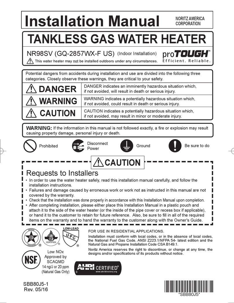
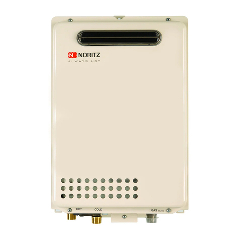
  9. Noritz proTOUGH NR83OD User manual

Noritz proTOUGH NR83OD User manual

This manual suits for next models

4

Other Noritz Water Heater manuals

Noritz ecOTOUGH NRC1111-OD-LP User manual

Noritz

Noritz ecOTOUGH NRC1111-OD-LP User manual

Noritz N-0751M-DVC User manual

Noritz

Noritz N-0751M-DVC User manual

Noritz NRC83-DV User manual

Noritz

Noritz NRC83-DV User manual

Noritz GQ-2457WS-FFA US User manual

Noritz

Noritz GQ-2457WS-FFA US User manual

Noritz N-0841MC User manual

Noritz

Noritz N-0841MC User manual

Noritz GQ-C5032WZ US User manual

Noritz

Noritz GQ-C5032WZ US User manual

Noritz GQ-C3257WZ-FF US User manual

Noritz

Noritz GQ-C3257WZ-FF US User manual

Noritz NR501-OD User manual

Noritz

Noritz NR501-OD User manual

Noritz NRCR111DV User manual

Noritz

Noritz NRCR111DV User manual

Noritz NR662-OD User manual

Noritz

Noritz NR662-OD User manual

Noritz NCC1991-DV User manual

Noritz

Noritz NCC1991-DV User manual

Noritz NR83-DVC User manual

Noritz

Noritz NR83-DVC User manual

Noritz N-0751M User manual

Noritz

Noritz N-0751M User manual

Noritz NC199-DVC-CA User manual

Noritz

Noritz NC199-DVC-CA User manual

Noritz GQ-2457WS US User manual

Noritz

Noritz GQ-2457WS US User manual

Noritz NRC1111-DV User manual

Noritz

Noritz NRC1111-DV User manual

Noritz EZ111DV User manual

Noritz

Noritz EZ111DV User manual

Noritz GQ-C2857WS-FF US User manual

Noritz

Noritz GQ-C2857WS-FF US User manual

Noritz N-0631S User manual

Noritz

Noritz N-0631S User manual

Noritz NRC1111-OD User manual

Noritz

Noritz NRC1111-OD User manual

Noritz NC250-DV-ASME User manual

Noritz

Noritz NC250-DV-ASME User manual

Noritz GQ-2857WX-F US User manual

Noritz

Noritz GQ-2857WX-F US User manual

Noritz NRCP111-DV User manual

Noritz

Noritz NRCP111-DV User manual

Noritz proTough NR98SV User manual

Noritz

Noritz proTough NR98SV User manual

Popular Water Heater manuals by other brands

clage German pool CEX13 operating instructions

clage

clage German pool CEX13 operating instructions

DeDietrich KALIKO TWH 200 EV Installation and service manual

DeDietrich

DeDietrich KALIKO TWH 200 EV Installation and service manual

veito FLOW Installation and operating instructions

veito

veito FLOW Installation and operating instructions

ICI Caldaie COSMOGAS AGUATANK 150 Instructions for installation, use and maintenance manual

ICI Caldaie

ICI Caldaie COSMOGAS AGUATANK 150 Instructions for installation, use and maintenance manual

Savio Laser 11 A Instruction manual for installation and use

Savio

Savio Laser 11 A Instruction manual for installation and use

Kenmore 153.582400 Use & care guide

Kenmore

Kenmore 153.582400 Use & care guide

STIEBEL ELTRON Eltronom SHU 5 S Operating and installation instructions

STIEBEL ELTRON

STIEBEL ELTRON Eltronom SHU 5 S Operating and installation instructions

clage E-Mini Series Operating and installation instructions

clage

clage E-Mini Series Operating and installation instructions

Solar SunX 317365-002 instruction manual

Solar

Solar SunX 317365-002 instruction manual

Bradford White EF Series Service manual

Bradford White

Bradford White EF Series Service manual

Dimplex ECSd125-580 Installation and user instructions

Dimplex

Dimplex ECSd125-580 Installation and user instructions

Dux 32FCR6N installation manual

Dux

Dux 32FCR6N installation manual

TESY GCV7/4S 10047 Instructions for use and maintenance

TESY

TESY GCV7/4S 10047 Instructions for use and maintenance

A.O. Smith Gphe 50 instruction manual

A.O. Smith

A.O. Smith Gphe 50 instruction manual

Rinnai REP199i Installation and operation manual

Rinnai

Rinnai REP199i Installation and operation manual

Toyotomi Oil Miser OM-148 (Type D) Operation and maintenance instructions

Toyotomi

Toyotomi Oil Miser OM-148 (Type D) Operation and maintenance instructions

Koryo KWHZF15Y user manual

Koryo

Koryo KWHZF15Y user manual

Pentair PSC-14-4-02 Installation and operation manual

Pentair

Pentair PSC-14-4-02 Installation and operation manual

manuals.online logo
manuals.online logoBrands
  • About & Mission
  • Contact us
  • Privacy Policy
  • Terms and Conditions

Copyright 2025 Manuals.Online. All Rights Reserved.

Potential dangers from accidents during installation and use are divided into the following three
categories. Closely observe these warnings, they are critical to your safety.
Prohibited Disconnect
Power Ground Be sure to do
WARNING: If the information in this manual is not followed exactly, a re or explosion may result
causing property damage, personal injury or death.
NORITZ AMERICA
CORPORATION
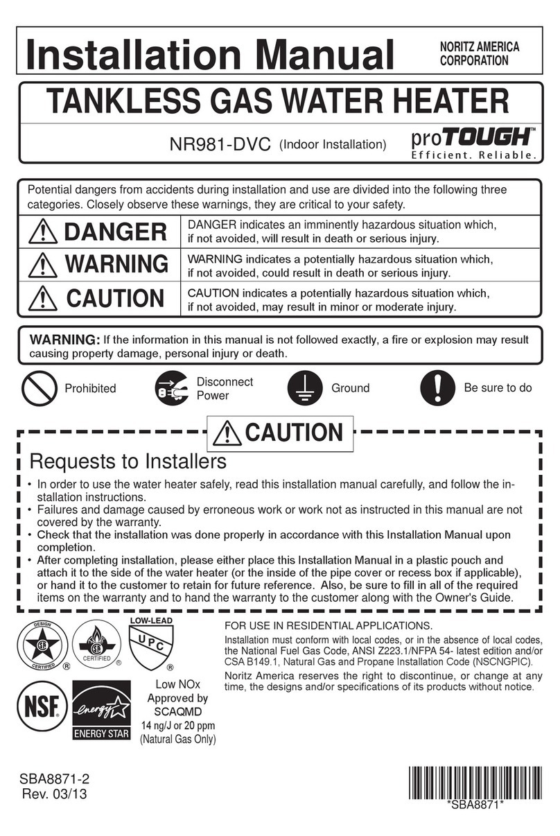
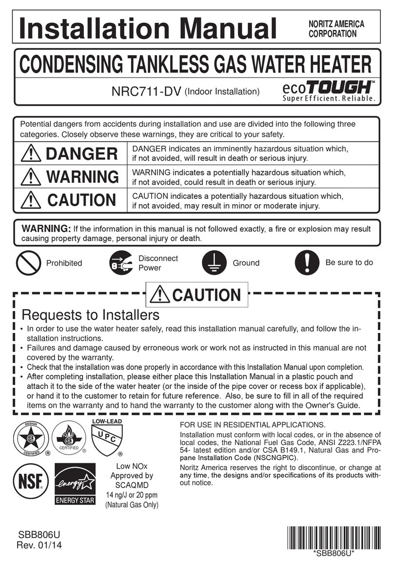
Installation Manual
TANKLESS GAS WATER HEATER
NR83OD (GQ-2457WS US) (Outdoor Installation)
DANGER indicates an imminently hazardous situation which,
if not avoided, will result in death or serious injury.
WARNING indicates a potentially hazardous situation which,
if not avoided, could result in death or serious injury.
CAUTION indicates a potentially hazardous situation which,
if not avoided, may result in minor or moderate injury.
DANGER
WARNING
CAUTION
SBB80YR-1
Rev. 11/20
Requests to Installers
• In order to use the water heater safely, read this installation manual carefully, and follow the
installation instructions.
• Failures and damage caused by erroneous work or work not as instructed in this manual are not
covered by the warranty.
• Check that the installation was done properly in accordance with this Installation Manual upon
completion.
•
After completing installation, either place this Installation Manual in a plastic pouch and attach it to
the side of the Water Heater (or the inside of the pipe cover or recess box if applicable), or hand it
to the customer to retain for future reference.
CAUTION
*SBB80YR*
FOR USE IN RESIDENTIAL OR MANUFACTURED HOME APPLICATIONS.
Installation must conform with local codes, or in the absence of
local codes, the National Fuel Gas Code, ANSI Z223.1/NFPA 54-
latest edition and/or the Natural Gas and Propane Installation
Code CSA B149.1 - latest edition.
When applicable, installation must conform with the Manufactured
Home Construction and Safety Standard, Title 24 CFR, Part
3280 or the Canadian Standard CAN/CSA-Z240 MH Mobile
Homes, Series M86.
Noritz America reserves the right to discontinue, or change at any
time, the designs and/or specications of its products without notice.
Low NOx
Approved by
SCAQMD
14 ng/J or 20 ppm
(Natural Gas Only)
2
1.
Included Accessories
The following accessories are included with the unit.
Check for any missing items before starting installation.
Q’ty
ShapePart
1
each
Part Shape Q’ty
3
1
Remote Controller
(See p. 20) Remote Controller
Cord (6ft (2m))
1
2.
Optional Accessories
The accessories listed below are not
included with the units, but may be necessary
for installation.
Cross Recessed
Head Screw
Quick Connect Cord
(QC-2)
Q’ty
ShapePartPart Shape Q’ty
1
1
Remote Controller
Cord (26ft (8m))
1
each
Isolation Valves*
(includes pressure
relief valve)
Pipe Cover
(PC-2S) 1
1
Recess Box
(RB-700-1)
1
Remote Controller
Outdoor
Junction Box
Owner's Guide, Warranty,
Installation Manual
(this document)
* Isolation valves are necessary for ushing the Heat Exchanger.
They allow for easy ushing of the system.
Noritz Connect
Wireless Adapter
NWC-ADAPTER
(NAW-1 US)
1
3
Union
Quick Connect
cord
Union
Gas Valve
Shutoff
Valve
Shutoff Valve
Hot Water
Cold Water
Pressure
Relief
Valve
Union
Shutoff Valve
Size the piping to allow for the
maximum flow rates of the units.
The backflow preventer is
put up before it diverges.
Distance at center: 15.8 - 31.8 in. (401 - 808mm)
Distance on sides
2 - 18 in. (50 - 457mm)
Leave enough clearance around the plumbing to
apply insulation. It will be necessary to add
bends to the piping to ensure that this clearance
is available.
Make this distance as short
as possible.
*
The hot water temperature
will become unstable as the
pipe length increases.
G
Quick Connect
Cord
Remote Controller Cord
Gas Supply Piping
Cold Water Supply
Hot Water
Remote Controller
Terminal Block
Cord
Connector
Cord
Connector
3.
Quick Connect Multi System Installation
• The Quick Connect Multi System allows the installation of two units together utilizing only the Quick
Connect Cord.
* When connecting two units, use only a
single remote controller.
Note: Connect the remote
controller to only one
of the units.
System Diagram
• Insulate the hot water piping to prevent heat loss. Insulate and apply heating materials to the
cold water supply piping to prevent heat loss and freezing of pipes when exposed to excessively
cold temperatures.
The Quick Connect Cord is 6 ft.(2m) long. Install the units 2-18" (50 - 457mm) apart from each
other to ensure the cord will be able to reach between the units. (See Typical Plumbing diagram).
(If the distance between the two units is too great, not only will the cord not be able to reach,
but the water temperature may also become unstable because of the di󰀨erence in pipe length
between the two units).
Typical Plumbing
4
Check the Gas
• Check that the rating plate indicates the correct type of gas.
• Check that the gas supply line is sized for
180,000 Btuh.
Check the Power
• The power supply required is 120VAC, at 60Hz.
May result in re or electric shock.
Use Extreme Caution if Using With a Solar Pre-Heater
• Using this unit with a solar pre-heater can lead to unpredictable output temperatures and
possibly scalding. If absolutely necessary, use mixing valves to ensure output temperatures do
not get to scalding levels. Do not use a solar pre-heater with the quick-connect multi-system.
Precautions for Mobile Home Installation
• Verify that the gas supply type matches the gas type listed on the rating plate. If a gas conversion
must be done, follow the instructions listed in the gas conversion kit manual.
4. Before Installation
Do Not Use Equipment for Purposes Other Than Those Specied
• Do not use for other than increasing the temperature of the water supply, as unexpected accidents
may occur as a result.
Check Water Supply Quality
• If the water supply is in excess of 12 grains per gallon (200 mg/L) of hardness, acidic or otherwise
impure, treat the water with approved methods in order to ensure full warranty coverage.
WARNING
CAUTION
5. Choosing Installation Site
DANGER
Indoor
• This water heater is for outdoor installation only.
Never install it indoors.
Do not enclose the termination with corrugated
metal or other materials.
This will cause carbon monoxide
poisoning and a potential re
hazard.
* Locate the appliance in an area where leakage from the unit or connections will not result in damage
to the area adjacent to the appliance or to the lower oors of the structure. When such installation
locations cannot be avoided, a suitable drain pan, adequately drained, must be installed under the
appliance. The pan must not restrict combustion air ow.
* As with any water heating appliance, the potential for leakage at some time in the life of the product
does exist. The manufacturer will not be responsible for any water damage that may occur.
5
• Avoid places where res are common, such as those where gasoline,
benzene and adhesives are handled, or places in which corrosive gases
(ammonia, chlorine, sulfur, ethylene compounds, acids) are present.
Using the incorrect voltage may result in re or cracking.
• Avoid installation in places where dust or debris will accumulate.
Dust may accumulate and reduce the performance of the unit's fan.
This can result in incomplete combustion.
• Avoid installation in places where special chemical agents
(e.g., hair spray or spray detergent) are used.
Ignition failures and malfunction may occur as a result.
• Carbon Monoxide Poisoning Hazard. Do not install this water heater in a
recreational vehicle or on a boat.
• Install the water heater in a location where it is free from obstacles and stagnant air.
• Consult with the customer concerning the location of installation.
• Do not install the water heater near staircases or emergency exits.
• Do not install the water heater where the exhaust will blow on outer walls or material not resistant
to heat. Also consider the surrounding trees and animals.
The heat and moisture from the water heater may cause discoloration of walls and resinous materials,
or corrosion of aluminum materials.
• Do not locate the vent termination directed towards a window or any
other structure which has glass or wired glass facing the termination.
• Install in a location where the exhaust gas ow will not be a󰀨ected by
fans or range hoods.
• Take care that noise and exhaust gas will not a󰀨ect neighbors.
Avoid installation on common walls as the unit will make some
operational noises while it is running.
• Avoid installation where the unit will be exposed to excessive winds.
• Before installing, make sure that the vent termination will have the proper
clearances according to the National Fuel Gas Code (ANSI Z223.1-latest
edition ) or the Natural Gas and Propane Installation Code (CSA B149.1).
•
If the unit is installed in a location with very high humidity, condensate may form inside the unit and/or
cause incomplete combustion, damage to the electrical components, or electric leakage.
Prohibited
WARNING
CAUTION
Prohibited
State of California: The water heater must be braced, anchored or strapped to avoid moving during
an earthquake. Contact local utilities for code requirements in your area or call: 1-866-766-7489 and
request instructions.
The Commonwealth of Massachusetts:
1) This water heater can only be used in outdoor applications if the usage is restricted to summertime
usage exclusively.
2)
The water heater can be used for hot water only and not in a combination of domestic and space heating.
6
6. Installation Clearances
Before installing, check for the following:
Install in accordance with relevant building and mechanical codes, as well as any local, state or
national regulations, or in the absence of local and state codes, to the National Fuel Gas Code
ANSI Z223.1/NFPA 54 – latest edition. In Canada, see the Natural Gas and Propane Installation
Code CSA B149.1 - latest edition for detailed requirements.
WARNING
Item Check
• When installing the unit on a balcony, etc., secure an
evacuation route of 24" (600mm) or more in width.
• Provide clearance of 24" (600mm) or more in front of
the unit to facilitate inspection and repair. Do install the
unit in a location where the unit is out of reach, such as
the wall of the second oor.
• When installing the unit in a common side corridor, provide
a clearance of 47" (1,190mm) or more in front of the unit.
• Set the bottom edge of the exhaust port about
84" (2,130mm) from the corridor oor.
Handrail
common side
corridor
balcony, etc.
Handrail
about 84"
(2,130mm)
• Maintain the following clearance from both combustible
and non-combustible materials.
24" (600mm)
or more
36" (900mm)
or more
Surrounding the area of installation
24" (600mm)
or more
47" (1,190mm) or more
Required Clearances From Heater
Illustration
6" (150mm)
or more
7
Clearance Requirements from Vent Terminations to Building Openings
* All clearance requirements are in accordance with ANSI Z21.10.3 and the National Fuel Gas Code,
ANSI Z223.1 and in Canada, in accordance with the Natural Gas and Propane Installation Code
CSA B149.1.
DescriptionRef
A=
Clearance above grade, veranda, porch,
deck, or balcony
B=
Clearance to window or door that may
be opened
C=
Clearance to permanently closed window
D=
Vertical clearance to ventilated soffit located
above the terminal within a horizontal distance
of 2 feet (61 cm) from the center line of the terminal
*
E=
Clearance to unventilated soffit *
F=
Clearance to outside corner *
G=
Clearance to inside corner *
H=
Clearance to each side of center line
extended above meter/regulator assembly
I=
Clearance to service regulator vent outlet
J=
Clearance to nonmechanical air supply
inlet to building or the combustion air inlet
to any other appliance
K=
Clearance to a mechanical air supply inlet 6 ft (1.83 m)
L=
Clearance above paved sidewalk or paved
driveway located on public property
Clearance under veranda, porch, deck,
or balcony
7 ft (2.13 m)†
M=
1
In accordance with the current CSA B149.1 Natural Gas and Propane Installation Code
2
In accordance with the current ANSI Z223.1 / NFPA 54 National Fuel Gas Code
† A vent shall not terminate directly above a sidewalk or paved driveway that is located between two single
family dwellings and serves both dwellings.
‡ Permitted only if veranda, porch, deck, or balcony is fully open on a minimum of two sides beneath the floor.
* Clearance in accordance with local installation codes and the requirements of the gas supplier.
Clearance to opposite wall is 24 inches (60 cm).
12 in (30 cm)‡
*
12 in (30 cm)
6 in (15 cm) for appliances
≤ 10,000 Btuh (3kW), 12 in
(30 cm) for appliances > 10,000
Btuh (3kW) and ≤ 100,000 Btuh
(30 kW), 36 in (91 cm) for
appliances > 100,000 Btuh (30 kW)
Above a regulator within 3 ft (91 cm)
horizontally of the vertical center line of
the regulator vent outlet to a maximum
vertical distance of 15 ft (4.5 m)
4 ft (1.2 m) below or to side
of opening; 1 ft (300 mm)
above opening
6 in (15 cm) for appliances
≤ 10,000 Btuh (3kW), 12 in
(30 cm) for appliances > 10,000
Btuh (3kW) and ≤ 100,000 Btuh
(30 kW), 36 in (91 cm) for
appliances > 100,000 Btuh (30 kW)
4 ft (1.2 m) below or to side
of opening; 1 ft (300 mm)
above opening
*
*
*
*
**
*
*
*
3 ft (91 cm) above if within
10 ft (3 m) horizontally
*
12 in (30 cm)
US Non-Direct Vent Installation
2
Canadian Non-Direct Vent Installation
1
Vent Terminal
Air Supply Inlet
Area Where Terminal
is Not Permitted
8
Illustration
7. Installation
Check
4. Drill holes for the remaining four screws.
5. Hang the unit again by the rst screw, and then
insert and tighten the remaining four screws.
6. Take waterproong measures so that water does
not enter the building from screws mounting the
device.
• Make sure the unit is installed securely so that it will
not fall or move due to vibrations or earthquakes.
Securing to the wall
1. Drill a single screw hole, making sure to hit a stud.
2. Insert and tighten the screw and hang the unit by
the upper wall mounting bracket.
3. Determine the positions for the remaining four screws
(two for the top bracket and two for the bottom), and
remove the unit.
• The weight of the device will be applied to the wall. If the strength of the wall is not
su󰀩cient, reinforcement must be done to prevent the transfer of vibration.
• Do not drop or apply unnecessary force to the device when installing. Internal parts may
be damaged and may become highly dangerous.
• Install the unit on a vertical wall and ensure that it is level.
Locating Screw Holes
Mounting
Structure
• When installing with bare hands, take caution to
not inict injury.
• Be careful not to hit electrical wiring, gas, or water
piping while drilling holes.
Item
CAUTION
Be sure to do
Mounting Bracket
(upper)
Anchoring Screw
Location of Screw Hole
Locating Screw Holes
Installations at Elevations
Above 2,000 ft.
• Adjust the dip switches as illustrated in the table to
the right if this water heater is installed at an altitude
of 2000 ft. (610m) or higher.
• Disconnect power to the water heater before
changing the dip switches. Failure to perform this
step will result in a "73" code displayed on the remote
controller and a cease in operation. If this occurs,
disconnect, then reconnect power to the water heater
to reset the system.
Note : Please refer to page 20 for the location of the
dip switch bank.
* Do not change any other dipswitches.
* High elevation adjustment.
65
2,001 - 4,000 ft (611 - 1,220m)
0 - 2,000 ft (0 - 610m)
ON= OFF=
4,001 - 6,000 ft (1,221 - 1,830m)
6,001 - 8,000 ft (1,831 - 2,440m)
9
Follow the instructions from the gas supplier.
8. Gas Piping
Gas Type
The gas type indicated on the water heater rating plate (NG or LP) must match the type of gas being supplied to the water heater.
Gas Conversions
If the gas type supplied does not match the gas type on the rating plate, obtain a replacement unit with the proper gas type.
If a gas type conversion must be made, there are conversion kits available for some models. [The conversion kit shall be
installed by a qualied service agency in accordance with the manufacturer’s instructions and all applicable codes and
requirements of the authority having jurisdiction. The qualied service agency is responsible for the proper installation of
this kit. Improper installation of this kit will void the warranty.]
Meter
The gas meter must be sized properly for the water heater and other gas appliances to operate properly.
Select a gas meter capable of supplying the entire btuh demand of all gas appliances in the building.
The guidelines and examples we have provided in this manual section are for reference only.
The sizing and installation of the gas system for this water heater, as with any gas appliance, is the sole respon
sibility
of the installer. The installer must be professionally trained to do such work and must always follow all local
and national codes and regulations. Gas line sizing calculations must be performed for every installation.
Please contact Noritz America at 866-766-7489 if you have any questions or concerns.
CAUTION
Regulators
Ensure that all gas regulators used are operating properly and providing gas pressures within the specied range of the
water heater being installed. Excess gas inlet pressure may cause serious accidents.
Pressure
Check the gas supply pressure immediately upstream at a location provided by the gas company.
Supplied gas
pressure must be within the limits shown in the specications section with all gas appliances
operating. The inlet gas
pressure must be within the range specied. This is for the purposes of input
adjustment. Low gas pressure may
cause a loss of ame or ignition failure at other appliances in the home, which may result in unburned gas in the home.
Serious accidents such as re or explosion may result.
Measuring Gas Pressure
In order to check the gas supply pressure to the unit, a tap is provided on the gas inlet.
Remove the 9/32” hex head/Philips screw from the tap, and connect a manometer
using a silicon tube. Open up at least 2 xtures and hold in the maximum manifold
pressure button on the circuit board. Please call Noritz for details.
WARNING
CAUTION
Pressure Test
The appliance and its gas connections must be leak tested before placing the appliance in operation. The appliance
must be isolated from the gas supply piping system by closing its individual manual shuto󰀨 valve during any
pressure
testing of the gas supply piping system at test pressures equal to or less than ½ psig (3.5 kPa). We do
not recommend pressure testing in excess of ½ psig (3.5kPa). If it must be done, the appliance and its individual
shuto󰀨 valve must be completely disconnected from the gas supply piping system during the test process.
Pipe Sizing/Flexible Connectors
A gas shuto󰀨 valve must be installed on the supply line. Gas ex lines are not recommended unless the minimum
inside diameter is ¾” or greater and the rated capacity of the connector is equal to or greater than the BTU
capacity of the water heater. Gas piping shall be in accordance with local utility company requirements and/
or in the absence of local codes, use the latest edition of National Fuel Gas Code (NFPA54GC), ANSI
Z223.1. In Canada, use the latest edition of CSA B149.1, National Gas and Propane installation code.
Size the gas line according to total btuh demand of the building and length from the meter or regulator so
that the following supply pressures are available even at maximum demand.
WARNING
Natural Gas Supply Pressure
Min 4” WC
Max 10.5” WC
LP Gas Supply Pressure
Min 8” WC
Max 14” WC
10
Reference Tools & Sample Calculations
The tables and samples below are for reference only. The professional sizing and installing the gas
line should always run the appropriate calculations before all installations.
CAUTION
Which Table to Use
• For NG installations with the initial supply pressure at point of delivery (at the meter, for example) is
less than 8” WC, use the 0.5” WC pressure drop table (Table 1).
• For NG installations with the initial supply pressure at point of delivery is greater than or equal to 8”
WC, use the 3.0” pressure drop table (Table 2).
• For all LP installation use (Table 3)
The inlet pressure must be at least 5” WC for NG or 8” WC for LP for all appliances in the gas system.
If the inlet gas pressure drops below 5” WC for NG or 8” WC for LP, the heater may continue to operate,
but the other appliances in the house may experience ame loss or ignition failure, which can result in gas
leakage into the home. Refer to the NFPA 54 for details.
Please contact Noritz for details. For corrugated stainless steel tubing (CSST) capacity tables, please
consult with the manufacturer.
Pipe
Size
Length (including ttings)
10' 20' 30' 40' 50' 60' 70' 80' 90' 100' 125'
(3m) (6m) (9m) (12m) (15m) (18m) (21m) (24m) (27m) (30m) (38m)
3/4" 360 247 199 170 151 137 126 117 110 104 92
1" 678 466 374 320 284 257 237 220 207 195 173
1 1/4" 1,390 957 768 657 583 528 486 452 424 400 355
1 1/2" 2,090 1,430 1,150 985 873 791 728 677 635 600 532
2" 4,020 2,760 2,220 1,900 1,680 1,520 1,400 1,300 1,220 1,160 1,020
2 1/2" 6,400 4,400 3,530 3,020 2,680 2,430 2,230 2,080 1,950 1,840 1,630
3" 11,300 7,780 6,250 5,350 4,740 4,290 3,950 3,670 3,450 3,260 2,890
4" 23,100 15,900 12,700 10,900 9,660 8,760 8,050 7,490 7,030 6,640 5,890
Table 1. For Less than 8” WC initial supply pressure
Maximum Natural Gas Delivery Capacity (0.5” Pressure Drop) [Schedule 40 Metallic Pipe]
Values in Table are in Cubic Feet of Gas per Hour (0.60 Specic Gravity, 0.5” Pressure Drop, inlet pressure less than 2psi). Contact your gas
supplier for BTU/Cubic Foot ratings. For simplication of your calculations, 1 Cubic Foot of Gas is approximately equivalent to 1000 BTU.
Instructions
1. Size each outlet branch starting from the furthest
using the Btuh required and the length from the meter.
2. Size each section of the main line using the length to
the furthest outlet and the Btuh required by everything
after that section.
Sample Gas Line
Sample Calculation - (Using 0.5” WC Pressure Drop Table)
Outlet A: 45' (13.5m) (Use 50' (15m)), 50,000 Btuh requires 1/2"
Outlet B: 40' (12m), 65,000 Btuh requires 1/2"
Section 1: 45' (13.5m) (Use 50' (15m)), 115,000 Btuh requires 3/4"
Outlet C: 30' (9m), 35,000 Btuh requires 1/2"
Section 2: 45' (13.5m) (Use 50' (15m)), 150,000 Btuh requires 3/4"
Outlet D: 25' (7.5m) (Use 30' (9m)), 25,000 Btuh requires 1/2"
Section 3: 45' (13.5m) (Use 50' (15m)), 175,000 Btuh requires 1"
Outlet E: 25' (7.5m) (Use 30' (9m)), 180,000 Btuh requires 3/4"
Section 4: 45' (13.5m) (Use 50' (15m)), 355,000 Btuh requires 1 1/4"
Natural Gas
Meter
Noritz Tankless Gas Water Heater
(180,000 Btuh)
Clothes Dryer
(35,000 Btuh)
Barbecue
(50,000 Btuh)
Gas Range Stove
(65,000 Btuh)
10' (3m) 10' (3m)
10' (3m)
10' (3m)
5' (1.5m)
5' (1.5m)
5' (1.5m)
5' (1.5m)5' (1.5m) 5' (1.5m)
Gas Fireplace
(25,000 Btuh)
Section 3 Section 2 Section 1
Outlet A
Outlet B
Outlet C
Outlet D
Outlet E
Section 4