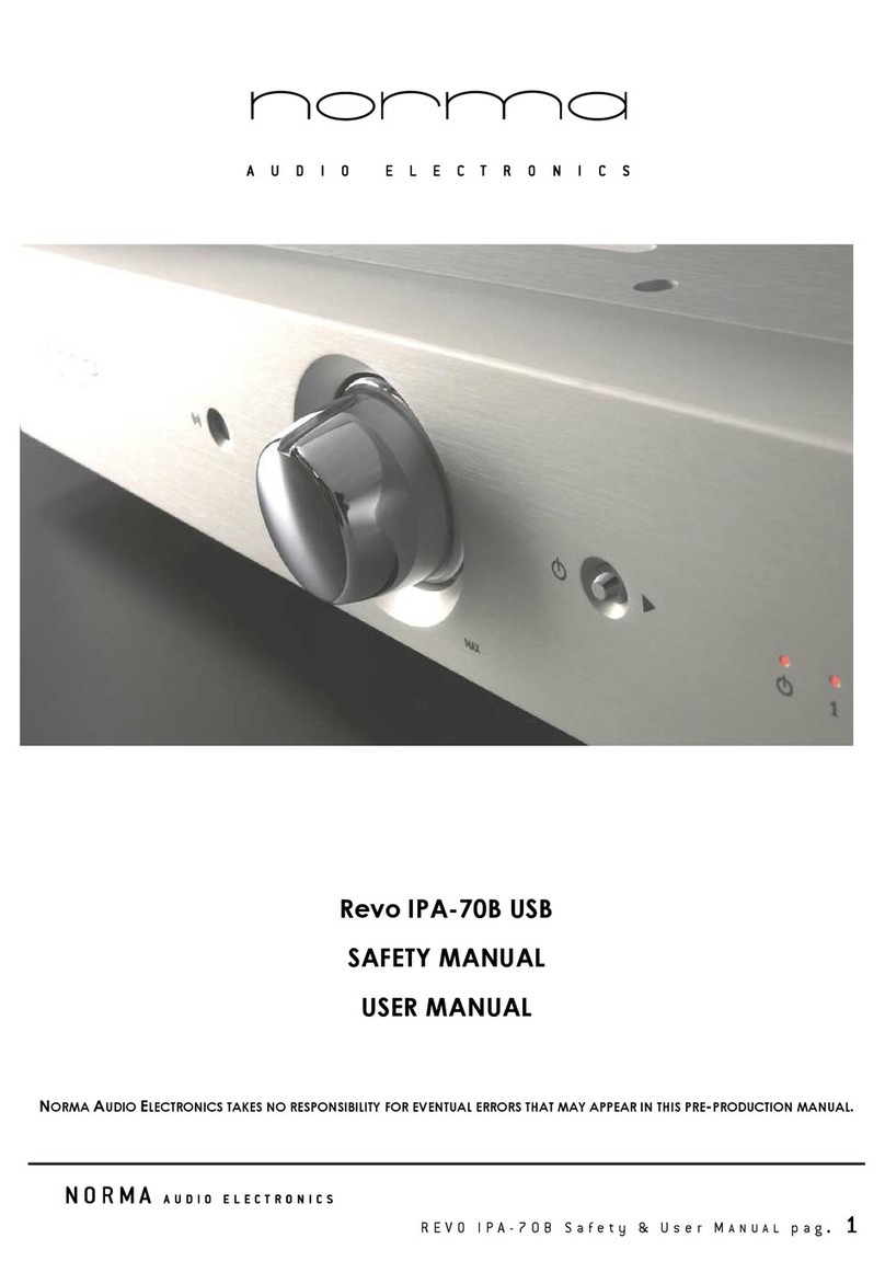
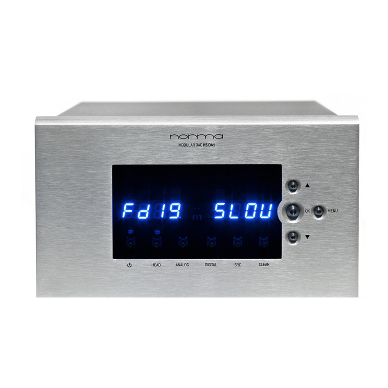
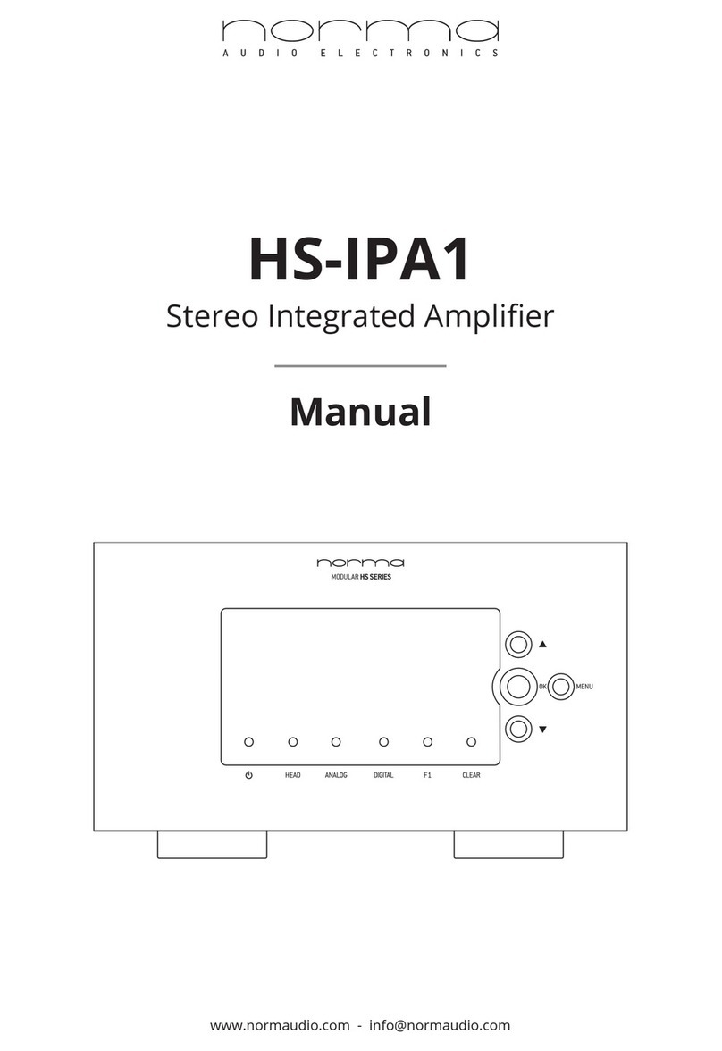
Norma HS-IPA1 User manual

N O R M A A U D I O E L E C T R O N I C S
H S - I P A 1 S a f e t y & U s e r M A N U A L p a g . 1
A U D I O E L E C T R O N I C S
HS-IPA1
SAFETY MANUAL
USER MANUAL
NORMA AUDIO ELECTRONICS TAKES NO RESPONSIBILITY FOR EVENTUAL ERRORS THAT MAY APPEAR IN THIS PRE-PRODUCTION MANUAL.

N O R M A A U D I O E L E C T R O N I C S
H S - I P A 1 S a f e t y & U s e r M A N U A L p a g . 2

N O R M A A U D I O E L E C T R O N I C S
H S - I P A 1 S a f e t y & U s e r M A N U A L p a g . 3
INDEX
SAFETY MANUAL
1 PRELIMINARY INDICATIONS
2 PACKING & UNPCKINGA
3 TRANSPORT AND POSITIONING
4 CONNECTIONS
5 MAINTENANCE AND SUPPORT
6 USAGE
7 REMOTE CONTROL
8 GENERAL
9 RECYCLING,
10 LIMITATION of USE in USA-CANADA-MEXICO
USER MANUAL
1 CONTROLS AND CONNECTION
2 USE
3 MAINTENANCE
4 SPECIFICATION
5 TESTING
6 USB CONNECTION GUIDELINES
7 REAR CONTROLS AND CONNECTIONS LIST

N O R M A A U D I O E L E C T R O N I C S
H S - I P A 1 S a f e t y & U s e r M A N U A L p a g . 4
Safety Manual
1 - PRELIMINARY INDICATIONS
Read this manual carefully before removing the unit from its packaging. Anyone considering it superfluous,
ignoring what said before assumes all responsibility for any accidents or incidents derived from improper use.
The manual explains the main safety rules that must be followed carefully: Failure to comply may result in
serious injury, as with any device or appliance powered by the mains voltage. They also learn how to use for
optimal performance and diversified products, and these, although machines for playing recorded music,
are designed to protect the user from hazards arising from the presence of voltage. Must be careful not to
touch live electrical parts wearers of cardiac devices electrically powered [peace maker] or therapeutic
devices for electric or electronic. The electrical safety is due to its connection to safety ground. Before
connection and use so make sure that the system grounding is efficient and the corresponding regulations.
NORMA is not responsible for any damage resulting from wrong system grounding or inefficient directives
and regulations. Also check that the mains voltage is the same as that which must be fed the equipment.
2 – PACKING & UNPACKING
Remove the machine from its packaging and place it in a horizontal position, resting on the lower legs. Play
attention to the material and packaging bags, should be stored in a dry place away from fire hazards,
given the nature of the materials they are made of. Should not be accessible to children to avoid the
danger of suffocation.
3 - TRANSPORT AND POSITIONING
Move and transport it carefully, taking care to maintain a firm and safe grip, do not place or carry it to
heights that can become dangerous in the event of a fall.
Place it on solid supports and surfaces, out of the reach of children.
The electronics must operate in a dry place sheltered from the weather of any kind. Do not expose the
electronics to any type of moisture, rain, vapour, spray mixtures. Keep the device away from sources of
electric fields, magnetic and electromagnetic fields. Never place in devices one above the other; they must
operate in a horizontal position in order to better dissipate the heat produced, but should never be
overlapped. The equipment must be installed away from sources of heat and direct sunlight, so as to allow
good air circulation.
3.1 TEMPERATURE
The device is designed to operate in normal domestic environments at a temperature ranging between 10
and 30 degrees centigrade. During operation of the amplifier, and for a time consistently long after it is
turned off, the heat sink can reach high temperatures and therefore dangerous to touch. Never touch the
heat sink during operation and for at least one hour after shutdown.
4 - CONNECTIONS
Be sure to read the writing found on covers and rear panels, study the layout and get a feel for subsequent
connections.
Connect inputs and outputs always with power turned off.
Allow at least 10 minutes after turning off the unit and not operate until the lights internal and / or external
prove still lit, even weakly. Be careful not to short or connect any of the terminals, you can damage
speakers and electronics. The last connection before use continues to be the power supply.

N O R M A A U D I O E L E C T R O N I C S
H S - I P A 1 S a f e t y & U s e r M A N U A L p a g . 5
5 - MAINTENANCE AND SUPPORT
The equipment must be checked by qualified personnel when:
- The power cord, the plug or the socket appear to be damaged;
- Objects, liquids or mixtures of any kind has been spilled into the appliance;
- The unit does not operate properly;
- The device has been dropped or damaged;
- The device emits an unusual odour or smoke;
Do not open or remove the cover under any circumstances. Not personally intervene to replace the fuses.
The operation, even in its own intrinsic banality, involves extremes caution and requires specialised
personnel who are familiar with electrical equipment and the ability to investigate the cause of the fault.
For any operation always contact a service center authorised by the manufacturer and that has original
spare parts. The inner tunnel must not be removed by anyone and for any reason: it is essential for the
isolation from the mains voltage. For any problem that assistance deemed to come from an element in
series with the mains voltage, the device must be sent to the manufacturer. The electronics must not be
altered or tampered with. In fact, despite the measures designed to protect the user, it is impossible to
predict any misuse of the equipment. Means for misuse any action contrary to the above issues or needs of
tool that disassemble, unscrew and remove mechanical and electrical parts of the product.
Failure to use original spare parts makes the device does not meet the design specification.
6 - USAGE
Avoid touching either directly or through objects and tools inside the case until it is connected to the
network: this action, as well as causing damage to the user because exposed to dangerous voltage may
damage the electronics.
- Do not remove the top cover for any reason, which is essential for the isolation from the high voltage inside.
During operation and as long as the equipment is connected to the mains for any reason do not touch the
metal part of the electrical connection terminals: at their ends may be present high voltages.
For cleaning do not use any type of solvent hate volatile substance, alcohol, spray or flammable. Never
clean the appliance during operation. For cleaning methods consult the owner's manual.
7 - WARNING USB INPUT
The optional USB input provided on the Norma REVO IPA-70B is designed to work with PCM signals of up to
192 KHz and DSD64 signal. The DSD signal MUST BE transmitted ONLY with “DSD OVER PCM” codification. Any
other use of DSD signal might not be recognized from the USB receiver and could result in unexpected
behaviours, which could seriously damage any equipment connected to the Norma REVO IPA-70B. Norma
takes no responsibility in any damage that may occur due to this wrong usage.
8 - REMOTE CONTROL
Use the remote control with the attention reserved for electronics in general, avoid exposing it to excessive
heat, humidity, magnetic fields and shocks that could affect its functionality. Use only alkaline batteries of
the type indicated in the remote control and insert them properly orienting the positive and negative poles.
Battery life varies depending on usage. Once discharged, not groped to refill them. The batteries should be
stored in appropriate containers for disposal with the least possible damage to the environment. Keep
batteries out of the reach of children and pets. Remove them from the remote control if you will not use it for
long periods.
9 - GENERAL
Failure to comply with any of the points above will void the warranty. The manual safety and operating
instructions must be kept with the packaging and always accompany the appliance for moving or shipping.
For any problem of any kind please contact the manufacturer directly. Anyone who fails to comply with the
above particulars makes devices have been ineffective, the consequences of such actions in violation of
the rules of safety and will only be attributed to the irresponsible superficiality users. NORMA is not responsible
for any errors, omissions or incompleteness of this manual, as it is not responsible for accidents or damages of
any kind that may result from non-compliance, even partial, of the information provided in this manual.
Despite the effort to identify all possible situations of danger, is not responsible for any damage that may be
caused to people or things from improper use of the appliance or done against common sense.

N O R M A A U D I O E L E C T R O N I C S
H S - I P A 1 S a f e t y & U s e r M A N U A L p a g . 6
10 - RECYCLING
Caring for the Environment by Recycling
Legislative Decree 25 July 2005, 151
Implementation of Directives 2002/95/EC, 2002/96/EC and 2003/108/EC on the reduction of use of
hazardous substances in electrical and electronic equipment and the disposal of waste
This product is marked with the recycling regarding the disposal of electrical and electronic equipment. This
means that this product must be taken to a recycling center in accordance with Directive 2002/96/EC, so
that they can be recycled or dismantled so as to minimise the impact on the environment. Do not dispose
of this product as household waste. If no suitable collection systems, please contact the authorised service
center nearest you, your dealer or, in the case of Italy, please contact the manufacturer directly.
For more information on this you may want to contact your local or regional.
11 - LIMITATION of USE in USA-CANADA-MEXICO
The use of any NORMA AUDIO, OPAL ELECTRONICS product in USA, CANADA, MEXICO is authorized ONLY if
the product has been imported and sold by NORMA’s official distributor, as indicated on NORMA AUDIO
website (www.normaudio.com).
If the product is not sold by NORMA’s official distributor, in addition to the following documents:
- Safety Manual, User's Manual, warranty, conditions of service and repair - OPAL ELECTRONICS NORMA
makes
ABSOLUTE PROHIBITION OF USE of any of its products in the following countries:
UNITED STATES OF AMERICA, CANADA, MEXICO
As stated in the SECURITY MANUAL, in the USER MANUAL, and in the WARRANTY DOCUMENT, OPAL
ELECTRONICS and NORMA AUDIO strictly forbid the use of any kind of NORMA products in the following
countries: USA, CANADA, MEXICO.
In These country is strictly forbidden:
- To import (directly or agency)
- To sell
- To use (including occasional use or for short periods of time)
any kind of NORMA AUDIO product, unless the unit has been imported and sold by NORMA’s official
distributor.
Therefore, OPAL ELECTRONICS and NORMA AUDIO can not be held responsible for any loss or damage,
both direct or indirect, caused by unauthorised use of their products in the above mentioned countries.

N O R M A A U D I O E L E C T R O N I C S
H S - I P A 1 S a f e t y & U s e r M A N U A L p a g . 7
User Manual
Congratulations!
The product you have purchased and you are going to use is the result of a long process of research and
development, to bring you the best that current technology allows us to express in electronic intended for
audio playback, both in terms of construction quality that listening quality.
We are confident that you will find great satisfaction from the use of our products, which, if treated with
care, will reciprocate with a durable reliable. However, prior to use, is indispensable to read and transpose
the brief notes attached below.

N O R M A A U D I O E L E C T R O N I C S
H S - I P A 1 S a f e t y & U s e r M A N U A L p a g . 8
1 - CONTROLS AND CONNECTION
Refer to the attached drawing in the last pages of the manual
1.1 – Front Panel
1 - Multi-function display
The display show the controls and functional states.
2 - Indicator POWER STAND-BY
In the state of STAND-BY indicator is illuminated.
In the state of POWER ON indicator is off.
3 - MENU button
Enables and disables access to the setup functions of the operating parameters.
4 - Command CLEAR
Delete the data or selection.
5 - OK button
Confirms the data or the function active at that moment.
6 - Button [SEL-] [VOL-]
selection button BACK [-].
button to decrease volume [VOL-].
7 – Button [SEL +] [VOL +]
NEXT selection button [+].
button to increase the volume [VOL +].
8 – HEAD (works only with HEADPHONE option mounted)
Disables outputs and activates headphone output. A light turns on to signal the use of the headphone.
9 – ANALOG
Switches between analog inputs.
10 – DIGITAL (works only with DAC option mounted)
Switches between digital inputs.
1.2 - List of Controls and Rear Connections
A - ON / OFF switch.
B - Mains socket
Mains power connector. Slot for connection of the network cable according to IEC / CEE 22. Check that the
mains voltage corresponds to that indicated on the label on the rear panel.
C - Fuse
The AC power fuse. Verify that the voltage, the type and extent coincides with that indicated on the rear
panel. Attention!! For any reason the user must replace the fuse, it is a task reserved for qualified personnel in
the service centers.
D - Digital IN 1 : USB “B style” plug connections socket
Input socket for digital signal input 1.
E - Digital IN 2 : S/PDIF TOSLINK plug connection socket
Input socket for digital signal input 2.
F - Digital IN 3 : S/PDIF RCA plug connection socket
Input socket for digital signal input 3.
G - Digital IN 4 : S/PDIF RCA plug connection socket
Input socket for digital signal input 4.
H - Digital IN 5 : S/PDIF TOSLINK plug connection socket
Input socket for digital signal input 5.
I - IN 1: plug RCA connection sockets
Analog Input socket for signal IN 1 channel right / left.
L - IN 2 [PHONO]: plug RCA connection sockets
Analog Input socket for signal IN 2 channel right / left.
If the PHONO module is mounted, Input 2 is the phono input.
M - IN 3: plug RCA connection sockets
Analog Input socket for signal IN 3 channel right / left.

N O R M A A U D I O E L E C T R O N I C S
H S - I P A 1 S a f e t y & U s e r M A N U A L p a g . 9
N - IN 4 [REC OUT]: plug RCA connection sockets
Analog Input socket for signal IN 4 channel right / left.
Can be set as output by system menu.
See instructions in the manual.
O - Speakers output [positive] right channel
Output jack of positive power.
P - Speakers output [negative] right channel
Output jack of negative power.
Q - Speakers output [negative] left channel
Output jack of positive power.
R - Speakers output [positive] left channel
Output jack of negative power.
O – HEADPHONES: 6.3mm jack connection plug (only if HEADPHONE option is mounted)
Analog output socket for headphones. 16-600 Ohm.
1.3.2 – Note on the Connections
The device must be able to make the most of their features. Nothing in the listening chain should not be
overlooked, starting with the interconnect cables, which must be of excellent quality, very transparent and
neutral.
The NORMA products are of extremely high quality and should be given them the opportunity to develop
the best performance.
Nothing in the listening chain should be underestimated, from the quality of the cables to the position of the
speakers.
For example, if cables used are of low quality the resulting sound will be much less than the potential of the
device.
1.4 – The Warm Up and Run In
The warm up is a fundamental factor. For the best sound performance, we recommend an initial run of
about 200 to 300 hours of operation with active speakers connected and music played at a normal listening
level. After a long period of inactivity, it is recommended to restore the run in. Similarly, to obtain the best
sound we recommend to warm up the product for at least 3 - 4 hours.
1.5 – The Problem of Hum
Frequently the connection of multiple devices can cause a certain amount of humming, even when the
individual devices are entirely silent. Connecting together the equipment can create ground loops, that for
induction introduce in the audio signal a certain amount of network harmonics. This problem, which also
affects the professional installations more sophisticated, is long-standing and not easy to solve; its influence is
particularly evident in the case of high gain amplifiers and in the presence of signals of very low amplitude.
The situation may sometimes be particularly critical with regard to the phono stages, turntables and
cartridges. We point out some possible remedies:
- Reduce the length of the connection cables;
- Change position of signal cables and power network;
- Increase the distance or arrange them in a different way;
- Avoid using devices that can induce electromagnetic fields or interference, such as electric motors,
fluorescent lights or lamps for low voltage transformers;
- It may be useful to raise the shields of the mass signal connection from one side of their termination. If a
device proves involved in hum problems and / or ground loops is made precise prohibition disconnect the
ground of electrical safety, contact the manufacturer instead to try to solve the problem.
- The electrical safety is due to its connection to safety ground. Before connecting and use the device,
make sure that the grounding system is efficient. . NORMA is not responsible for any damage resulting from
wrong system grounding or inefficient directives and regulations or a disconnection in any way made,
ground security equipment.
- Check that the power cable network has the ground connection and do not remove it for any reason.
- The new LED TV or PLASMA TV emit large amounts of infrared rays that can interfere with the IR remote
control signal.

N O R M A A U D I O E L E C T R O N I C S
H S - I P A 1 S a f e t y & U s e r M A N U A L p a g . 1 0
2 - USE
2.1 NORMA IR REMOTE DESCRIPTION
Some of the controls on the remote IR may be inactive for future use.
2.2 TURN ON \ OFF
The amplifiers of the HS series are equipped with a sophisticated power on system, integrated with the
system remote control and electronic protections. This system consists of three phases: POWER OFF, STAND-
BY, POWER ON [OPERATE].
2.2.1 POWER OFF: In this phase, the rear control switch is in the OFF position and the amplifier is off.
2.2.2 STAND-BY: placing the rear control switch in the ON position, the amplifier is active in STAND-BY POWER,
the stand-by light will turn on. This condition can be maintained indefinitely, the amplification stages are not
powered, but the amplifier is ready to receive the command switch.
2.2.3 POWER ON [OPERATE]: the power is on to all intents and purposes, this can be determined by the
prolonged action on the front POWER button or IR remote POWER button. In both cases, initially the screen
will show a countdown for a period of time equal to approximately 10 seconds. Subsequently, the screen will
show volume nd input information, indicating the complete operation of the amplifier and the connection
of the speakers.
2.2.4 STAND-BY: to bring the amp in STAND-BY, press the POWER button [or the POWER button on the remote
control], the stand-by light will turn on.
2.2.5 POWER OFF: to bring the amplifier in POWER OFF condition, after having acted on the POWER
command, put the rear control switch in OFF position. Never work directly on the rear control without first
place the amplifier in STANDBY.
2.2.6 ATTENTION: for safety reasons, after the unit is turned from POWER ON to STAND-BY mode, it is not
possible to turn it on again for 30 seconds.
2.3 PROTECTION CIRCUIT
Inside the amplifier HS-IPA1 are present some sophisticated protection circuits that control the temperature
of the heatsinks, the presence of any offset current exceeding the limit value and the abnormal supply of
output current (short circuit).
2.3.1 THERMAL PROTECTION
In case of intervention of thermal protection amplifier will automatically shuts down and the Power indicator
goes completely off. You can not in any way turn it back on until the temperature has returned at the
correct value, and this will be indicated by the restart of the stand-by light. Only then you can repeat the
POWER ON procedure. The amplifier will not automatically turn on.
2.3.2 DC OFFSET PROTECTION
In case of protections for the presence of DC component output, the amplifier turns off and the power
indicator switches to low intensity flashing. You can turn it back on only after switching off the appliance at
the rear switch and leaving it off for at least 10 seconds.
If the fault persists, the amplifier would run again in terms of protection. In this case, try to disconnect all
signal cables and repeat the process of restarting the unit. Should the situation persist, contact your service
representative.
2.4 INPUTS SELECTION
With the device turned on, you can select the desired input both via RC and front panel. On the remote
control, press the IN button, then select the desired input with the SEL + and SEL – buttons, then press OK.
On the front panel, press the ANALOG or DIGITAL buttons, select the desired input with the arrows, then
press OK.
2.5 SELECTION OF OUTPUT REC OUT
2.6 LISTENING VOLUME CONTROL
The listening volume can be adjusted using the function keys VOL-/ VOL + on the front panel or on the
remote.

N O R M A A U D I O E L E C T R O N I C S
H S - I P A 1 S a f e t y & U s e r M A N U A L p a g . 1 1
2.7 CONNECTING THE SPEAKERS
The speakers should be connected by wires to the SPEAKERS OUTPUT of adequate quality and diameter [at
least 4 mm イ].
In addition:
- The connection cables must have the same length for both channels even if the distance between the
speakers and the amplifier should be different;
- The cables must not be folded or rolled;
- The safety regulations require that the cables must not be pushed into the sockets of the amplifier via 4mm
banana terminations;
- Nominal impedance of the speaker must have not less than 4 ohms;
- The speakers should not be connected in parallel with each other.
Caution: To prevent damage, each connection must be done when the appliance is switched off and
unplugged from the mains.
2.8 – Functional Settings, Set Command
With the MENU (SET on RC) button you can set various functional parameters, as described in the following
paragraphs. In conjunction with the SEL +, SEL -, OK.
It 's possible to access many settings "nested" within the MENU function. Once you press MENU you can
access the following configuration menus using the SEL +, SEL- buttons
1 System Settings SYS set
2 Analog Settings ANaL sEt
3 Digital Settings DIgI SET (only with Digital Input Board mounted)
2.8.1 – System Settings
This section lets you customize all the characteristics of your device. You will find the submenus RESUME,
LIGHT, DISPLAY and OUT (HS-DA1 VAR only)
RESUME rESU
Stores the current settings and makes it default.
LIGHT LIGH
Adjusts display brightness between values 30, 50. 70, 100.
DISPLAY DISP
When OFF, enables display to turn off automatically after a few seconds without commands.
OUT 4 OUt4
When ON, the IN4 becomes an output (fixed level). When OFF, the IN4 is a standard input.
Attention: when enabled, be sure to NOT CONNECT any INPUT to the IN4, only use it as output.

N O R M A A U D I O E L E C T R O N I C S
H S - I P A 1 S a f e t y & U s e r M A N U A L p a g . 1 2
2.8.2 – Analog Settings
This sections lets you set the volume levels for every set of inputs (digital if present, analog 1-4).
If you leave the setting in OFF, when selecting an input it will keep the current volume. If you define a
specific value, when selecting the input, the unit will automatically turn the volume control in that position.
In everyone of these section you will find two submenus, LINE and HEAD. LINE HEAD
LINE:
VOLUME: can be set between -5 and -45, or in OFF position
HEAD:
VOLUME: can be set between -5 and -45, or in OFF position
Note: the HEAD settings are present only if the HEAD option is mounted.
The VOLUME option sets a reference value for the input, to easily handle sources with different output levels
without constantly adjusting the volume manually. In OFF mode it doesn’t manage the volume storing.
2.8.3 – Digital Settings
Not present on preliminary manual and units.
2.9 – Display Modes
When outside the setting menu, the display can show two different kinds of information.
1. As standard, it will show the input in use and the current volume.
2. When a volume button is pressed, it shows VOL and the current volume.
2.10 – Volume Control
To adjust the volume, the user has two possibilities: by using the volume control on the remote, or by using
the buttons 6 - Button [SEL-] [VOL-] and 7 – Button [SEL +] [VOL +] on the front panel.
Every time you act on the volume control, the display shows the attenuation value.
NOTE ON VOLUME CONTROL AND DISPLAY:
In order to be more useful to the user, the volume indication is converted in Decibels of attenuation,
between approximately 0 and -50 dB.
Anyway, because of this scale conversion process, there may be some visualization imprecisions (for
example, the maximum volume may stop at -2/-1 dB).
The user should not be concerned by this, as the whole attenuation range offered by the volume control
(from 0 to around -80 dB) is effectively used.

N O R M A A U D I O E L E C T R O N I C S
H S - I P A 1 S a f e t y & U s e r M A N U A L p a g . 1 3
2.11 – Remote Control (16 buttons)
1 - ON/OFF
Turns the device on or puts it in stand-by.
2 - MUTE
Mutes the outputs. The device will not accept other commands until mutes is pressed again.
3 - VOL +/-
Adjusts the volume.
4 - SEL +/-
Navigate through menus.
5 - DSY (RC only)
Adjusts display brightness
6 - CLR
It has the same function of the CLEAR button on the front panel, it deletes the data or selection.
7 - SET
It has the same function of the MENU button on the front panel, it enables and disables access to the setup
functions of the operating parameters.
8 - IN
Lets you select between inputs.
9 - DAC
Not active on this device.
10 - A/P
Not active in this device.
11 - AMP and DIG
They select which device the remote control is driving.
For HS-DA1 use DIG mode.
12 - F1/SRC
Toggles oversampling. If a specified value has been set in the setting menu, it applies that value, otherwise it
goes in AUTO mode.

N O R M A A U D I O E L E C T R O N I C S
H S - I P A 1 S a f e t y & U s e r M A N U A L p a g . 1 4
2.12 – Headphones (Optional)
The optional headphone output of the HS-IPA1 is a very high quality one, able to gracefully drive even the
most demanding headphones. It is possible to set it in 4 different positions via internal jumpers, to best fit it for
each kind of headphone. The default position is position 2 (32 Ohm).
To access the internal jumpers, you need to disconnect the unit from the power supply, leave it off for 10
minutes, and then proceed to remove the top panel by unscrewing the 10 screws that hold it (5 on each
side). These are Torx T10 screws, for which you need an appropriate Torx screwdriver.
Once you have removed the top, the headphone setting jumpers are located on the rear-right side of the
unit, next to the headphone output.
Important: the jumpers must be positioned in VERTICAL position (see photos)
The following pictures show how to position the jumper to achieve the 4 settings. Remember that the
jumpers are in groups of 2 and that they must be moved on both boards (left and right channels)
POSITION 1 – 16 Ohm
||------
||------

N O R M A A U D I O E L E C T R O N I C S
H S - I P A 1 S a f e t y & U s e r M A N U A L p a g . 1 5
POSITION 2 – 32-60 Ohm (default)
POSITION 3 – 200-600 Ohm
POSITION 3 – Direct Connection - ATTENTION
In this position the headphone is connected directly to the power output, the same that drives the speakers.
This position is to be used only with very particular headphones taht need high power to drive. Do not use
this position with standard speakers.
--||----
--||----
----||--
----||--
------||
------||

N O R M A A U D I O E L E C T R O N I C S
H S - I P A 1 S a f e t y & U s e r M A N U A L p a g . 1 6
3 - MAINTENANCE
3.1 CLEANING
Before cleaning the unit turn it off, unplug it from the electricity supply and wait at least 10 minutes. Your
device has been designed with the best technical solutions combined with an aesthetic finish of the highest
quality, but for it to remain unchanged over time, it is essential to observe the following methods:
- Don't dry-clean surfaces and in particular the front panel;
- Lightly dampen the cloth with a small amount of warm water (40-50 degrees);
- Make circular movements and do not press hard on the panel.
- Dry off gently, always with cotton or a soft cloth, making a very delicate circular motion.
- Be very careful to avoid that water penetrates into, the cloth should be moist but not wet.
- Do not reconnect the unit until it is completely dry.
- Under no circumstances use alcohol, solvents, gasoline or any type of chemical product.
Please note that the finish and aesthetic components are in no way covered by the warranty.
3.2 REPAIRS
For any inconvenience refer to the safety manual. The products are the result of precision engineering with
sophisticated circuitry and extreme components. Therefore require, in case of failure, of a highly qualified
assistance that has absolutely original spare parts.
The manufacturer is available to clients for any problem. NORMA is not responsible for any errors, omissions
or incompleteness of this manual, as it is not responsible for accidents or damages of any kind that may
result from non-compliance, even partial, of the information provided in this manual. Despite the effort to
identify all possible danger situations, NORMA is not responsible for any damage that may be caused to
people or from improper use.

N O R M A A U D I O E L E C T R O N I C S
H S - I P A 1 S a f e t y & U s e r M A N U A L p a g . 1 7
4 SPECIFICATIONS
Specifications HS-IPA1
Inputs
4 Line, 1 Tape IN, Input DIRECT
Phono at IN-2 (OPTIONAL), DIGITAL (USB, TOSLINK, S/pdif) (OPTIONAL)
Inputs
Impedance
4 Line, = 10 Kohm
Phono
Gain 36 dB / 1 kHz, Input Impedance 47 Kohm as default
See phono user manual for alternative settings.
Outputs
1 REC OUT, 2 pair of Main Speakers Outputs,
Frequency Response
0-800 KHz (Volume at MAX)
Power
2 x 75 W RMS / 8 Ohm - 150 W RMS / 4 Ohm
Outputs Current
24 A continuous, 100 A peak (each channel)
Sensitivity
(Volume at MAX)
480 mV for 75 W / 8 Ohm
Gain
(Volume at MAX)
34 dB (55mV – 1W / 8 Ohm)
Supply
230 V AC / 50 Hz, (100V AC or 115 VAC / 50-60Hz in some country)
Dimensions (HxWxD)
126 x 215 x 350 mm
Note
Integrated amplifier with full remote control by NORMA IR
In order to improve its products, NORMA reserves the right to vary all the technical specifications and
appearance without notice.

N O R M A A U D I O E L E C T R O N I C S
H S - I P A 1 S a f e t y & U s e r M A N U A L p a g . 1 8
5 TESTING
Model
HS-IPA1
Version
__________________________________________________________
Accessories
__________________________________________________________
Serial Number
__________________________________________________________
First Tester
__________________________________________________________
Second Tester
__________________________________________________________
Third Tester
__________________________________________________________
Date
__________________________________________________________

N O R M A A U D I O E L E C T R O N I C S
H S - I P A 1 S a f e t y & U s e r M A N U A L p a g . 1 9
Other manuals for HS-IPA1
1
Table of contents
Other Norma Amplifier manuals
