NORMAGRUP NormaLux C24 User manual

P2843 SEP20
Central
Battery
System
C24
User guide

Index
1. Introduction
2. Technical Data
3. C24-100 mounting
4. C24-300 mounting
5. Electrical connection
6. Main pannel
7. Functioning of the unit
8. Screens directory
9. MENU screen
10. INFO screen
11. CONTROLS screen
12. OPTIONS screen
13. SETTINGS screen
14. Distances andwire sections calculation
15. Index of failures
16. Index of warnings
17. Modbus integration
Central
Battery
System
C24
User guide
Page
1
1
3
5
8
12
13
15
17
18
22
23
25
28
29
30
30
Spanish version

1. Introduction
C24 ttings allow to remotely supply power to 24Vdc luminaries. There are two models depending on
the output power:
· C24-100 (100W)
· C24-300 (300W).
These are intelligent domotic devices which give warnings about possible anomalies both in the centrals
themselves and / or in the lines where the emergency lighting is connected.
It is possible to control the centrals from a PC.
24Vdc permanent outputs available.
3 24 Vdc (50w max.) relay outputs controlled by BUS.
In this gued you will nd detailed information about the C24 centrals and its conguration.
2. Technical data
· Voltage: 230 V AC +/- 10%.
· Wire section: 2,5 mm2.
· Output voltage: 24 V DC +/- 20%.
· Outputs wire section: 2,5 mm2.
· Working temperature: -5ºC to 25ºC.
· Class: I.
· IP30.
· Outputs: 4.
· Maximum current: 3,5 A on each output.
· Dimensions:
· C24-100: 340 x 330 x 90 mm.
· C24-300: 500 x 400 x 200 mm.
1
Central
Battery
System
C24
User guide

Batteries
Duration
Total output voltage
I max (A)
C24-100
1h 3h 8h 1h 3h 8h
2x12V · 9Ah2x12V · 7Ah
88W 36W 14W 115W 48W 19W
3,86 1,70 0,76 4,97 2,19 0,97
Input phase monitor YES
Output control 4
Potential free contact relay
Functioning indicator
Battery functioning indicator
Fail
Power supply indicator
Battery supply indicator
Alarm / Fail indicator
Complete discharge
indicator
Active output indicator
BUS communication
YES
Batteries
Duration
Total output voltage
I max (A)
Input phase monitor
Output control
Potential free contact relay
Functioning indicator
Battery functioning indicator
Fail
Power supply indicator
Battery supply indicator
Alarm / Fail indicator
Complete discharge
indicator
Active output indicator
BUS communication
2x12V · 12Ah 2x12V · 18Ah 2x12V · 24Ah
1h 3h 8h 1h 3h 8h 1h 3h 8h
154W 66W 27W 234W 105W 42W 314W 136W 58W
6,62 2,92 1,30 9,94 4,39 1,95 13,25 5,85 2,60
C24-300
4
2
Central
Battery
System
C24
User guide
YES
YES
YES
YES
YES
YES
YES
YES
YES
YES
YES
YES
YES
YES
YES
YES
YES
YES
YES
YES

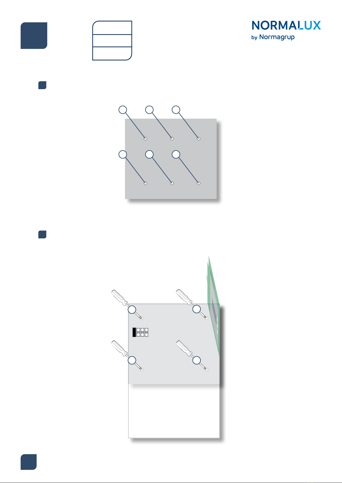
3. C24-100 mounting
3
Remove the 4 screws and open the front cover.
1Step
Use the ring under the PCB to move the circuit. Break open the pre-cutted holes for the wiring.
2Step
21
3 4
ring
Central
Battery
System
C24
User guide

Fix the tting to the wall using the three holes in the housing.
3Step
Connect the tting with 230 Vac y 50 Hz between L y N and the earth connection.
4Step
1
2 3
L N
4
Central
Battery
System
C24
User guide

5
Place the two batteries in the lower part of the housing and connect them. Close the central.
5Step
1 2
4. C24-300 mounting
Take out the screw and remove the frontal panel by pulling the cover up and then pulling the cover
towards you.
1Step
1
Central
Battery
System
C24
User guide
6
Fix the back plate to the wall.
2Step
Screw the housing of the central to the back plate that has been xed to the wall and secure the screws
rmly.
3Step
1 2 3
4 5 6
12
3 4
Central
Battery
System
C24
User guide

7
Connect the power supply to the 230Vac 50 Hz terminal block between L and N and the earth
terminal. Make the wiring to the luminaires in each one of the available outputs (OUT) and in case
that auxiliary inputs and outputs are needed (see drawings in the following pages). After this, please
connect the batteries and place the cover of the central.
4Step
Central
Battery
System
C24
User guide
The maximum number of luminaires to be connected in a central can be calculated following the
table on page 2, with a maximum power limint of 3.5A on each of the 4 outputs (although some
countries establish a limit of 12 or 20 units per output). The power of each tting is a feature of the
tting itself, so this must be checked in its technical datasheet.
The distance and cable section to be used in the outputs is calculated following the instructions on
page 28.
LN
1 2
Emergency lighting (C24)
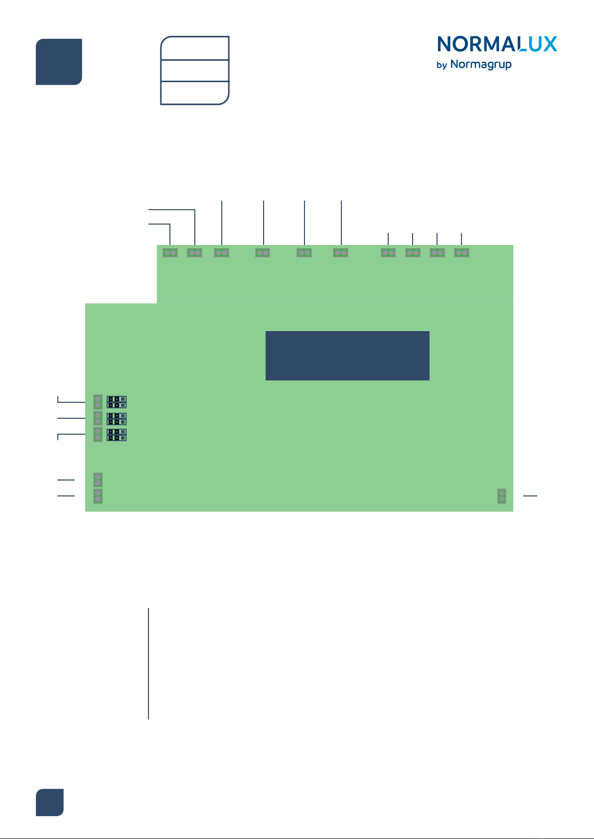
5. Electrical connection
OUT AUX
SL
OUT 1 OUT 2 OUT 3 OUT 4
LSS1 LSS2 LSS3 LSS4
SYSTEM
WORK
BATT
SUPPLY
FAIL
BAT2
BAT1
+
-
+
-MODBUS
A
B
· SL (Sense Loop): Input to connect a phase monitor. If this is not connected it should remain jumpered.
· OUT AUX: Auxiliary output to interconnect centrals by means of the SL (Sense Loop) output.
·
· OUT 1: Output 1.
· OUT 2: Output 2.
· OUT 3: Output 3.
· OUT 4: Output 4.
24v y 3,5A max. outputs, protected against short-circuit, by fuse and electronic
cut. These outputs include an amperimeter (class <1.5). It is able to inform the
controller about the exact amount of current in the mentioned output.
It also provides a small current (when the tting is o) to turn a green LED
installed in the luminaries on.
8
RELAYS
JUMPERS
Central
Battery
System
C24
User guide
This manual suits for next models
2
Table of contents
Popular Camera Accessories manuals by other brands

Viltrox
Viltrox EF-NEX Mount instructions

Calumet
Calumet 7100 Series CK7114 operating instructions

Ropox
Ropox 4Single Series User manual and installation instructions

Cambo
Cambo Wide DS Digital Series Main operating instructions

Samsung
Samsung SHG-120 Specification sheet

Ryobi
Ryobi BPL-1820 Owner's operating manual


