Norsat LNB User manual

USER MANUAL
LNB 1:1 Redundant Switch
ODU FW Version: 1.0.0
IDU FW Version: 1.0.0

© Norsat International Inc. (“Norsat”) All Rights Reserved
2021-12-20 DOC-001527 Rev A 2
TABLE OF CONTENTS
TABLE OF CONTENTS............................................................................................................. 2
Acronyms................................................................................................................................... 3
Safety ........................................................................................................................................ 4
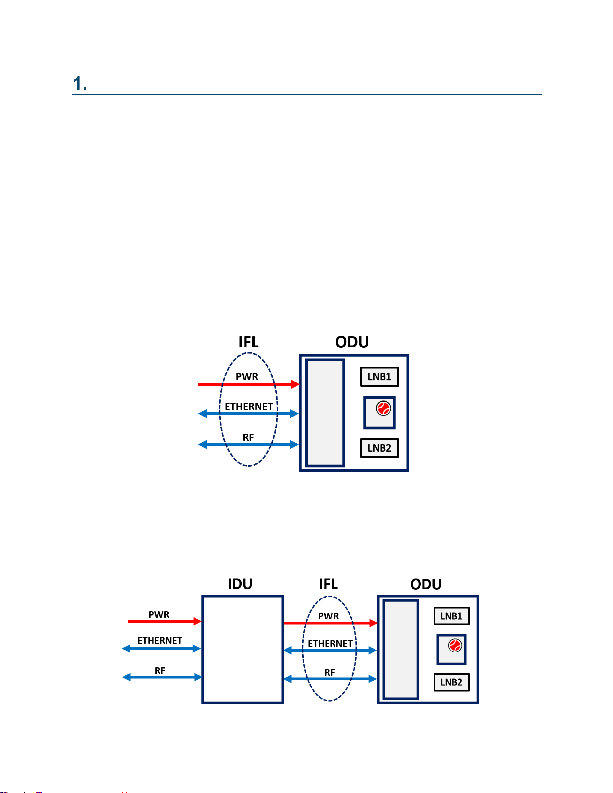
LNB 1:1 Redundant Switch System Overview.................................................................... 5
1.1 Operation..................................................................................................................... 5
1.2 System......................................................................................................................... 5
Getting Started................................................................................................................... 6
2.1 Warnings ..................................................................................................................... 6
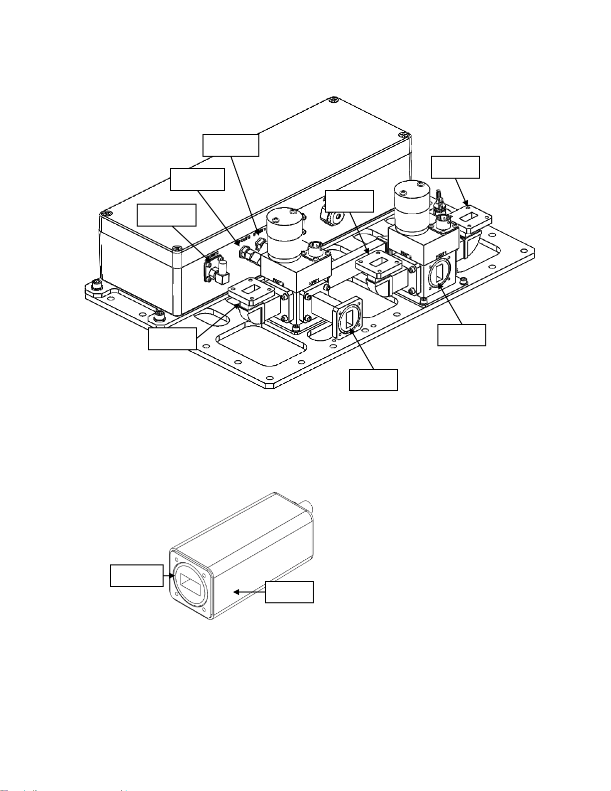
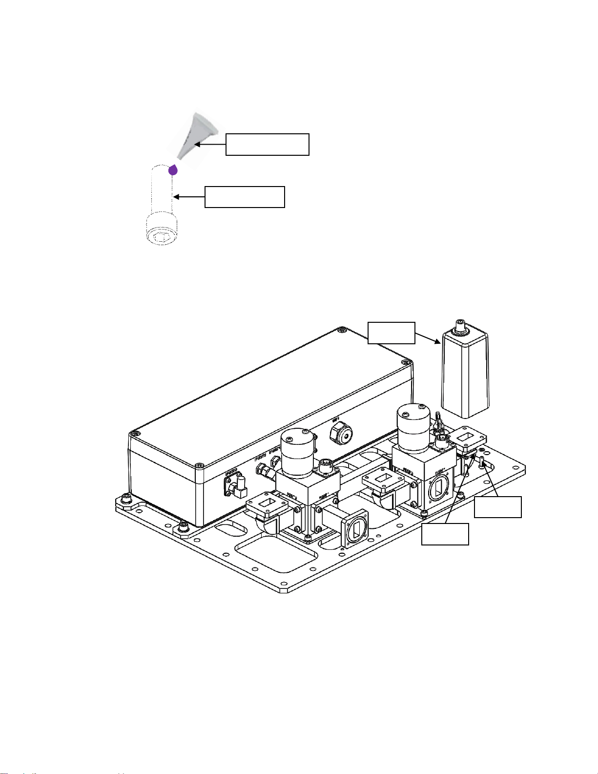
2.2 ODU Setup.................................................................................................................. 6
2.3 ODU IFL installation....................................................................................................16
2.4 IDU installation (Optional)...........................................................................................17
2.5 Safety Ground.............................................................................................................18
ODU Monitoring and Control.............................................................................................19
3.1 Fault Monitoring..........................................................................................................19
3.2 Operation Mode..........................................................................................................19
3.3 LNB Power .................................................................................................................20
3.4 Default Network Settings.............................................................................................21
3.5 LNB Replacement.......................................................................................................21
3.6 Web Interface .............................................................................................................21
3.7 SNMP.........................................................................................................................27
3.8 ODU Manual Override Switch.....................................................................................30
3.9 Factory Reset .............................................................................................................31
IDU Operation...................................................................................................................34
4.1 Front Panel.................................................................................................................34
4.2 LCD Screen................................................................................................................36
4.3 IDU Web Interface ......................................................................................................45
System Troubleshooting....................................................................................................48
System Maintenance.........................................................................................................49

© Norsat International Inc. (“Norsat”) All Rights Reserved
2021-12-20 DOC-001527 Rev A 3
Acronyms
AC
Alternating Current
CI
Control Interface
IDU
Indoor Unit
IFL
Interfacility Link
LNB
Low-noise Block Downconverter
RF
Radio Frequency
SNMP
Simple Network Management Protocol
ULC
Universal LNB Controller

© Norsat International Inc. (“Norsat”) All Rights Reserved
2021-12-20 DOC-001527 Rev A 4
Safety
Warning
Changes or Modifications to Equipment
Changesormodificationstothisequipment,notexpresslyapprovedbythe
manufacturer, could void the user’s authority to operate the equipment.
Warning
Accessories and Devices
Useofnon-approvedaccessoriesordevicesmayleadtoadegradationin
performance, damage to equipment, or potential hazards.
Warning
AC Power
This device uses AC power. Proper grounding of equipment is necessary
for safety purposes.

© Norsat International Inc. (“Norsat”) All Rights Reserved
2021-12-20 DOC-001527 Rev A 5
LNB 1:1 Redundant Switch System Overview
1.1 Operation
The LNB 1:1 Redundant Switch system (RSW) provides LNB redundancy by automatically switching to a
backup LNB in the event of an LNB failure. During normal operation, there is one Active LNB and one
Standby LNB which are both monitored continuously. LNB health monitoring is accomplished by watching
the LNB active power consumption. If the active LNB falls outside of a specified window, the RSW
automatically switches to the backup LNB.
1.2 System
1.2.1 Headless Operation (ODU Only)
The RSW is headless, meaning that it can be operated without the use of an Indoor Unit (IDU).
All monitoring and control (M&C) can be performed over Ethernet using the Web Interface or via
SNMP. TheOutdoor Unit(ODU) contains all control circuitry and is connected to the user’s system
through the Interfacility Link (IFL).
1.2.2 System with Optional IDU
The Indoor Unit (IDU) is an optional add-on which provides a 1U server rack with an M&C
interface. The IDU interfaces with the ODU via an LCD panel and buttons, and has configurable
alarms in the event of an ODU fault.

© Norsat International Inc. (“Norsat”) All Rights Reserved
2021-12-20 DOC-001527 Rev A 6
Getting Started
This section will outline the RSW installation and setup.
2.1 Warnings
If the RSW is configured for AC power, before powering on the unit, make sure that
the system is properly grounded. This is required for safety purposes.
Do not open the ODU controller box lid while the system is powered on.
Inspect all cables for damage prior to connecting them to the system.
2.2 ODU Setup
2.2.1 Ku/Ka-Band LNB Installation
LNB installation for Ku-band and Ka-band components are identical, except different sized
fasteners are provided.
The following components are included with the LNB mounting kit.
Item 1 (Socket Cap Screw)
Item 2 (Washer)
Item 3 (Loctite)
8x for 1:1 RSW
12x for 2:1 RSW
8x for 1:1 RSW
12x for 2:1 RSW
1x
The following tools are required. (Not included with the mounting kit)
Tool 1 (Hex Key)
M2.5 for Ka-Band
M3 for Ku-Band
Note the interfaces shown below.

© Norsat International Inc. (“Norsat”) All Rights Reserved
2021-12-20 DOC-001527 Rev A 7
(Interfaces for Rx In 2, IF Out 3 and LNB 3 are only present in 2:1 redundant switches)
Repeat the following steps for each LNB interface:
1. Remove any tape on the waveguide interface.
2. Insert the gasket included with the LNB into the groove on the LNB.
LNB 1
LNB 2
LNB 3
Rx In
1
Rx In
2
IF Out 1
IF Out
2
IF Out 3
LNB
Gasket

© Norsat International Inc. (“Norsat”) All Rights Reserved
2021-12-20 DOC-001527 Rev A 8
3. On the thread of Item 1, apply two to three drops of Item 3. Repeat this step for four
times.
4. Install the LNB onto the Rx In of redundant switch using the Item 1from step 3 above
and one Item 2 on each Item 1 with Tool 1.
5. Connect the LNB to the IF Out port with the matching number for the LNB position.
(i.e. LNB 1 connects to IF OUT 1)
Item 1
Item 3
LNB
Item 1
Item 2

© Norsat International Inc. (“Norsat”) All Rights Reserved
2021-12-20 DOC-001527 Rev A 9
2.2.2 C-Band LNB Installation
The following components are included with the LNB mounting kit.
Item 1 (Socket Cap Screw)
Item 2 (Washer)
Item 3 (Threadlocker)
14x
14x
1x
Item 4 (Gasket)
Item 5 (Adaptor Plate)
Item 6 (Set Screw)
2x
2x
6x
Item 7 (Nut)
6x
The following tools are required (not included with the mounting kit).
Tool 1 (Hex Key)
Tool 2 (Hex Key)
Tool 3 (Wrench)
3/16”
1/8”
7/16”
Note the interfaces shown below.

© Norsat International Inc. (“Norsat”) All Rights Reserved
2021-12-20 DOC-001527 Rev A 10
LNB 1
LNB 2
Rx In
IF Out 1
IF Out 2

© Norsat International Inc. (“Norsat”) All Rights Reserved
2021-12-20 DOC-001527 Rev A 11
Repeat the following steps for each LNB interface:
1. Remove any tape on the waveguide interface.
2. On the end opposite to the socket head of Item 6, apply two to three drops of Item 3.
Complete this step for three Item 6.
3. Fasten Item 6 from step 2 above into the LNB interface using Tool 2.
Item 6
Item 3
Socket Head
Item 6

© Norsat International Inc. (“Norsat”) All Rights Reserved
2021-12-20 DOC-001527 Rev A 12
4. Insert Item 4 into the LNB interface on the redundant switch and align Item 5 onto Item 6
installed from step 3 above.
5. Insert the gasket included with the LNB into the groove on the LNB.
Item 4
Item 5
LNB
Gasket

© Norsat International Inc. (“Norsat”) All Rights Reserved
2021-12-20 DOC-001527 Rev A 13
6. On the thread of Item 1, apply two to three drops of Item 3. Complete this step for five
Item 1.
6. Install the LNB onto the Rx In of redundant switch using Item 1 fromstep 5 above and
one Item 2 on each Item 1 with Tool 1.
Item 1
Item 3
Item 2
Item 1

© Norsat International Inc. (“Norsat”) All Rights Reserved
2021-12-20 DOC-001527 Rev A 14
7. Fasten Item 7 onto Item 6 installed onto the redundant switch using Tool 3.
8. Tighten all surrounding screws and nuts to fasten the LNB onto the redundant switch.
9. Connect the LNB to the IF Out port with the matching number for the LNB position.
(i.e. LNB 1 connects to IF OUT 1)
Item 7

© Norsat International Inc. (“Norsat”) All Rights Reserved
2021-12-20 DOC-001527 Rev A 15
2.2.3 Baseplate installation
Refer to the diagram below for the location of all mounting holes on the redundant switch
baseplate. Depending on the redundant switch configuration, some holes may be inaccessible.
Follow these general guidelines when mounting the redundant switch:
•Engage a minimum of 15 holes
•Use medium strength threadlocker

© Norsat International Inc. (“Norsat”) All Rights Reserved
2021-12-20 DOC-001527 Rev A 16
2.3 ODU IFL installation
This section covers the steps to install the IFL to the ODU.
The IFL consists of:
•1 x Power cable
•1 x Ethernet cable
•1 x RF Cable
1. Locate the ODU side of the IFL (labeled “ODU”).
2. Attach the RF cable to the IF1 connector as shown below.
3. Attach the PWR connector to the ODU. Ensure that the cable is threaded onto the
connector.
4. If you have purchased the optional IDU, proceed to Section 2.4. If the RSW is being
operated in the headless configuration, you can now power on the system by connecting
the PWR cable to AC power.

© Norsat International Inc. (“Norsat”) All Rights Reserved
2021-12-20 DOC-001527 Rev A 17
2.4 IDU installation (Optional)
This section outlines the steps to install the IDU.
1. Connect the ODU RF cable to one of the IF PASS THRU connectors. Use the applicable
RF connector type for the IFL provided.
2. Connect the modem RF cable to the unused IF PASS THRU connector.
a. If the IFL uses an N connector, the modem must also be connected to the N PASS
THRU section.
b. If the IFL uses an F connector, the modem must also be connected to the F PASS
THRU section.
3. Connect the Ethernet RJ-45 connector from the IFL to the ETH ODU port.
4. (Optional) Connect the Network port to any external network connection (cable not
included).

© Norsat International Inc. (“Norsat”) All Rights Reserved
2021-12-20 DOC-001527 Rev A 18
5. Connect the AC OUT port to the AC Power connector on the IFL.
6. Connect the AC IN port to the IDU power cable. Ensure that the cable is threaded onto
the connector.
7. Power on the system.
2.5 Safety Ground
A safety ground connection point is provided on the ODU and IDU. If the AC power input has no
earth ground, it is strongly recommended to connect one at the ODU grounding point and IDU
grounding point (if applicable). The grounding point locations are shown below.
ODU Grounding Point
IDU Grounding Point

© Norsat International Inc. (“Norsat”) All Rights Reserved
2021-12-20 DOC-001527 Rev A 19
ODU Monitoring and Control
3.1 Fault Monitoring
The RSW monitors the current consumption of all LNBs. The system determines if a fault has
occurred based on the current thresholds listed below. These limits are user configurable through
the Web Interface, SNMP, or the optional IDU. It is the user’s responsibility to optimize these
thresholds based on the application.
Upper Limit: If the current rises above this value, an overcurrent fault will be triggered.
Upper Warning: If the current rises above this value, an overcurrent warning will be triggered.
Lower Warning: If the current falls below this value, an undercurrent warning will be triggered.
Lower Limit: If the current falls below this value, an undercurrent fault will be triggered.
3.2 Operation Mode
3.2.1 Automatic Mode
While the Manual Override is disabled, the RSW will run in Automatic Mode. While in Automatic
Mode, the RSW automatically switches from the Active LNB to the Standby LNB if there is a fault
present on the Active LNB. The table below summarizes the RSW actions based on the fault
status while in Automatic Mode.
STATE
ACTION
Fault on active device
RSW will automatically switch to standby if there are no faults
present on the standby device
Fault on standby device
No action taken
Fault on both devices
No action taken
Manually Switching to standby
device
RSW will switch will only allow switching if there are no faults
on the standby device

© Norsat International Inc. (“Norsat”) All Rights Reserved
2021-12-20 DOC-001527 Rev A 20
3.2.2 Manual Override Mode
While the Manual Override is enabled, the RSW will run in Manual Override Mode. In this mode,
the RSW does not take any action based on the fault state of the LNBs. This mode allows the
user to select what LNB is active without restrictions. The table below summarizes the RSW
actions based on the fault status while in Manual Override Mode.
STATE
ACTION
Fault on active device
No action taken
Fault on standby device
No action taken
Fault on both devices
No action taken
Switching to standby device
RSW will switch to the standby device
3.3 LNB Power
3.3.1 Integrated ULC
The RSW has an integrated Universal LNB Controller (ULC) which can be configured by the user.
When the ULC setting is enabled, both the Active and Standby LNB receive power from the ULC.
The table below outlines the output voltage and tone for each configurable band. In the case that
a single band LNB is used, the system will be limited to BAND 1.
Parameter
VOLTAGE
22kHz TONE
BAND 1
13V
OFF
BAND 2
18V
OFF
BAND 3
13V
ON
BAND 4
18V
ON
3.3.2 Power over IF Cable
If the power to the LNB is being supplied by an external source, the ULC must be set to
DISABLED. In this operating mode, the Active Device is supplied with the IF power and the
Standby Device is provided with 18V.
Table of contents
Popular Switch manuals by other brands

Pilz
Pilz PSEN cs1.13p operating manual

EnGenius
EnGenius EWS Series user manual

United Electric Controls
United Electric Controls J120 Installation and maintenance instructions

Alaxala
Alaxala AX1250S Series Software manual

Theben
Theben TIMEGUARD IS3N-20 Installation & operating instructions

Inficon
Inficon VSA100A operating manual

NTI
NTI UNIMUX Series Installation and operation manual

EUCHNER
EUCHNER STP-TW AS1 Series operating instructions

Avocent
Avocent SwitchView SwitchView 1000 Specifications

Votronic
Votronic D+ Simulator Installation and operating manual

ANTAIRA
ANTAIRA Lanolinx LNX-1002GN user manual

ATEN
ATEN CS 1642 quick start guide