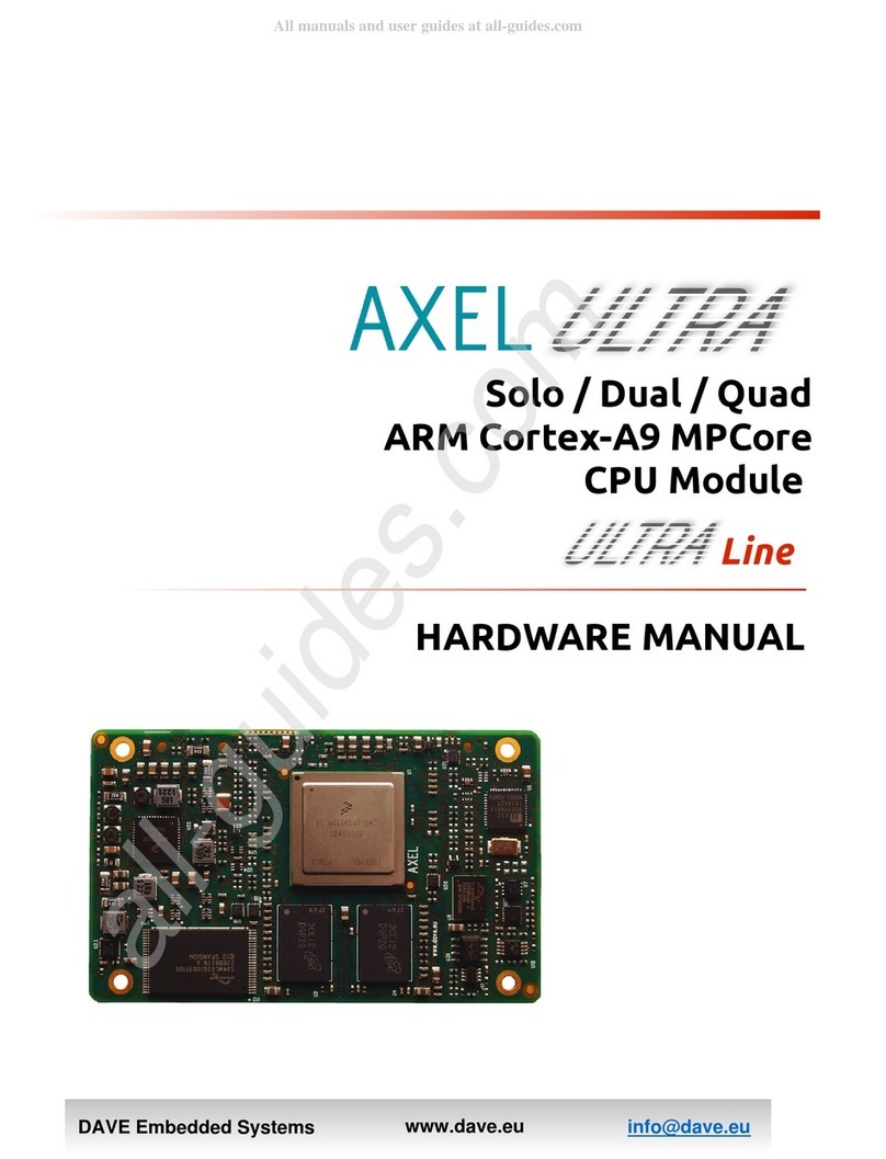
North Atlantic VXI 65CS4 User manual

Model 65CS4
MULTI-CHANNEL SYNCHRO/RESOLVER
STIMULUS AND MEASUREMENT
North Atlantic Industries, Inc. 631.567.1100/631.567.1823 (fax) 8/14/2013 65CS4_A001 Operations Manual Rev C6
110 Wilbur Place, Bohemia, NY 11716 www.naii.com Cage Code: 0VGU1 Page 1 of 38
VXI bus
Four (4) Instrument Grade Synchro/Resolver Measurement Channels
Four (4) Instrument Grade Synchro/Resolver Stimulus Channels
or
Eight (8) Embedded Grade Synchro/Resolver Stimulus Channels
FEATURES
INSTRUMENT Grade (High Accuracy) and/or EMBEDDED Grade (Moderate Accuracy w/ High Channel Count)
Multiple functions on a single slot VXI card
±0.005° Instrument Grade Measurement and Stimulus Accuracy
±0.015° Embedded Grade Stimulus Accuracy (higher channel density / lower accuracy)
47 Hz to 4,000 Hz (see part number).
(for 47 Hz to 10 KHz or 20 KHz, contact factory )
User programmable output voltages
2.2 VA Stimulus Outputs
2.2 VA Programmable Reference Generators
Simultaneous and independent Measurement and Simulation
Single-Speed or Multi-Speed Programmable for Measurement and Simulation
Programmable Multi-Speed Ratios (2 to 255)
Dynamic address configuration
VXIbus data rate of 2 megabytes/sec
Data is processed within 100s
Self-Test capability
As direct replacement for 5410C-89, use P/N 65CS4-A2200G0-A2100G0-M and cable harness 07-0018.
As direct replacement for B5410C-89-1, use P/N 65CS4-A2200G0-A2101G0-M and cable harness 07-0021.

North Atlantic Industries, Inc. 631.567.1100/631.567.1823 (fax) 8/14/2013 65CS4_A001 Operations Manual Rev C6
110 Wilbur Place, Bohemia, NY 11716 www.naii.com Cage Code: 0VGU1 Page 2 of 38
DESCRIPTION
This single slot VXI (“C”-size card) is an Instrument/Embedded Grade, intelligent DSP design, that incorporates
up to four Synchro/Resolver Measurement channels, and up to four Instrument Grade Synchro/Resolver
Simulation channels or up to eight Embedded Grade Synchro/Resolver (Simulation) channels that can be used
independently and/or simultaneously. The internal modular design of the card utilizes a motherboard that may be
populated with up to two daughter cards. Each daughter card, instrument grade or embedded grade, may each be
populated with S/D, D/S or REF modules, depending on the grade type (see configurations following).
Instrument Grade is defined as 0.005° Accuracy
Embedded Grade is defined as 0.015° Accuracy (less accurate than Instrument Grade but offers a higher
channel density.
Two Reference Supplies are available (one on each daughter card). If > 2 Reference supplies are required, the
additional Reference(s) will replace Stimulus channels (contact factory for special configurations).
All measurement and simulation channels are user programmable for either Synchro or Resolver format and may
be formatted for either single-speed or multi-speed applications. Programmable speed ratios (2:1 to 255:1) offer
additional flexibility for those applications requiring two-speed capability.
Each Simulation channel can be programmed for either continuous rotation or programmable Start and Stop
angles.
This instrument contains all the necessary functions to fully evaluate, calibrate and simulate the Synchro/Resolver
components and systems. With its built-in reference generators, superb accuracy, resolution and high power
output capability, this module can form the basis of a fully integrated system for testing any Synchro/Resolver
signal. This design also incorporates our new internal wrap-around Self Test capability that does not require any
external hardware.
21st Century technology combined with nearly 50 years of synchro/resolver product experience yield state-of-the-
art performance and accuracy.

North Atlantic Industries, Inc. 631.567.1100/631.567.1823 (fax) 8/14/2013 65CS4_A001 Operations Manual Rev C6
110 Wilbur Place, Bohemia, NY 11716 www.naii.com Cage Code: 0VGU1 Page 3 of 38
TABLE OF CONTENTS
FEATURES ................................................................................................................................................................1
DESCRIPTION...........................................................................................................................................................2
GENERAL ARCHITECTURE.....................................................................................................................................4
SPECIFICATIONS......................................................................................................................................................6
MOTHERBOARD -- GENERAL ........................................................................................................................................................6
APPLICABLE TO THE OVERALL CARD: ...........................................................................................................................................6
DAUGHTER-BOARD –INSTRUMENT GRADE ...................................................................................................................................6
General Configuration.........................................................................................................................................................6
Instrument Grade Measurement, Input Module(s)..............................................................................................................6
Instrument Grade Stimulus, Output Module(s)....................................................................................................................7
REFERENCE GENERATOR............................................................................................................................................................7
DAUGHTER-BOARD –EMBEDDED GRADE......................................................................................................................................8
General Configuration.........................................................................................................................................................8
Embedded Grade Stimulus, Output....................................................................................................................................8
OVERALL UNIT POWER REQUIREMENTS /MATRIX ..........................................................................................................................8
CARD ADDRESS.......................................................................................................................................................9
FRONT PANEL STATUS INDICATORS...................................................................................................................9
PROGRAMMING......................................................................................................................................................10
NATIVE SYNTAX .......................................................................................................................................................................10
Software / Driver Support .................................................................................................................................................10
SSK Details:......................................................................................................................................................................10
Formal Syntax Notation....................................................................................................................................................10
General Command Definition............................................................................................................................................11
Detailed Command Syntax...............................................................................................................................................12
Instrument Setup Queries.................................................................................................................................................17
MATE/CIIL SYNTAX ..................................................................................................................................................................18
COMMANDS ....................................................................................................................................................................18
NOTATION.......................................................................................................................................................................18
ERROR MESSAGES:.......................................................................................................................................................22
EXAMPLE.........................................................................................................................................................................22
CALIBRATION.........................................................................................................................................................23
CALIBRATION VERIFICATION TEST SET-UP......................................................................................................23
INTERNAL REFERENCE CHECKOUT PROCEDURE ..........................................................................................................................23
SINGLE-SPEED GENERATION (SIMULATOR)INTERNAL REFERENCE CHECKOUT PROCEDURE............................................................23
SINGLE-SPEED GENERATION (SIMULATOR)EXTERNAL REFERENCE CHECKOUT PROCEDURE ..........................................................24
TWO-SPEED GENERATION (SIMULATOR)CHECKOUT PROCEDURE.................................................................................................25
GENERATION (SIMULATOR)ANGLE RATE CHECKOUT ...................................................................................................................26
SINGLE-SPEED MEASUREMENT (API) INTERNAL REFERENCE CHECKOUT PROCEDURE ...................................................................26
SINGLE-SPEED MEASUREMENT (API) EXTERNAL REFERENCE CHECKOUT PROCEDURE ..................................................................26
TWO-SPEED MEASUREMENT (API) CHECKOUT PROCEDURE ........................................................................................................27
GENERATOR (SIMULATOR)DC RATE OUTPUT CHECKOUT PROCEDURE.........................................................................................27
FIELD ALIGNMENT.................................................................................................................................................28
FIGURES FOR CALIBRATION VERIFICATION TEST SET-UP ..............................................................................................................29
CONNECTOR CONFIGURATION...........................................................................................................................33
FRONT PANEL CONNECTOR PLACEMENTS /DESIGNATIONS ..........................................................................................................34
PART NUMBER DESIGNATION.............................................................................................................................35
APPENDIX A – CE...................................................................................................................................................36
REVISION HISTORY................................................................................................................................................38

North Atlantic Industries, Inc. 631.567.1100/631.567.1823 (fax) 8/14/2013 65CS4_A001 Operations Manual Rev C6
110 Wilbur Place, Bohemia, NY 11716 www.naii.com Cage Code: 0VGU1 Page 4 of 38
GENERAL ARCHITECTURE
This universal card eliminates the need for specialized simulation and measurement for Synchro/Resolver
components and systems. The card architecture consists of a motherboard with two daughter-boards that enable
the user to specify a variety of functions within this single slot card design. (See part number for details).
The daughter-boards consist of independent measurement / stimulus / reference modules that may be populated
to provide up to four Synchro/Resolver Measurement channels and up to four Instrument Grade
Synchro/Resolver Simulation channels or up to eight Embedded Grade Synchro/Resolver (Simulation) channels
that can be used independently and/or simultaneously.
Fig 1. Instrument / Embedded Board Daughter Card Combination
– Typical configuration example: (Note) – One or two Daughter Boards can be mixed / matched (at factory /
time of order) to suit configuration preference.
– If a second and/or third reference supply is specified on an Instrument Grade daughter card, it replaces
D/S channel 2 then 1 respectively and only RHi and RLo (S1, S3) pins are active. (Please contact factory
for special configuration requests).

North Atlantic Industries, Inc. 631.567.1100/631.567.1823 (fax) 8/14/2013 65CS4_A001 Operations Manual Rev C6
110 Wilbur Place, Bohemia, NY 11716 www.naii.com Cage Code: 0VGU1 Page 5 of 38
Ready
Access
Failed
Test
J1
J2
USB
Factory Use
S/D Module
(Up to two channels)
REF Module
(Dedicated 2-115 Vrms programmable)
D/S Module
(One CH / 2-90 VLL)
D/S Module
(One CH / 2-90 VLL)
Daughter-Board - Instrument Grade
Daughter-Board - Converter Grade
Mother Board
S/D Module
(Up to two channels)
REF Module
(Dedicated 2-115 Vrms programmable)
D/S Module
(One CH / 2-90 VLL)
Daughter-Board - Instrument Grade
D/S Module
(One CH / 2-90 VLL)
Fig 2. Dual Instrument Grade Daughter Board Combination
Fig 3. Dual Embedded Grade Daughter Board Combination

North Atlantic Industries, Inc. 631.567.1100/631.567.1823 (fax) 8/14/2013 65CS4_A001 Operations Manual Rev C6
110 Wilbur Place, Bohemia, NY 11716 www.naii.com Cage Code: 0VGU1 Page 6 of 38
SPECIFICATIONS
Motherboard -- General
DSP Design Dedicated DSP for VXI Bus Data Transfer
VXI Bus Data transfer 2 MB/sec
Daughter Card Configuration Up to (2) daughter-cards
ESD protection Designed to meet the testing requirements of IEC 801-2 level 2 (4KV transient
with a peak current of 7.5A with a time constant of approximately 60 ns.
Applicable to the Overall Card:
VXIBus Data Rate: 2 megabytes/second
Trigger: Rotation may be initiated by either an external (Front Panel) or via the trigger
bus. External trigger is terminated with a 499 resistor and is connected to a
differential Line Receiver (SN75115N). Trigger input to be 8 microseconds min
width.
Data states: Track or freeze for Measurement channels only
Temperature, Operating: 0C to +52C
Temp. Non-Operating: -40C to +71C
Relative Humidity: to 95% RH, non-condensing
Shock: Designed to meet 15G, 11 ms
Vibration: Designed to meet MIL-PRF-28800F for class 3 equipment.
Altitude, Operating: 15,000 feet
Altitude, Non-Operating: 40,000 feet
Size: "C" size (13.386" x 9.187"), 1.2" pitch. (349mm x 234 mm), 30 mm pitch
Weight: 4.3 lb.
Calibration Intervals: Annual verification is suggested
Cooling: 25 cfm @ 0.12”
Daughter-Board – Instrument Grade
General Configuration Up to (2) Instrument Grade Measurement channels
Up to (2) Instrument Grade Stimulus channels
(1) Reference channel (may be increased in lieu of stimulus channels)
Instrument Grade Measurement, Input Module(s)
Number of Channels: Up to four (see part number)
Input Mode: Angular Synchro/Resolver, programmable
Range: 0 – 359.9999
Resolution: 0.0002
Accuracy: (Resolver): ±0.005º at 47 to 4,000 Hz
±0.0083º at 5.0 KHz
±0.0167º at 10.0 KHz (2 - 28 V L-L)
(Synchro): ±0.005º at 47Hz to 1.0 KHz
Input Voltage (Resolver): 1.0 - 90 V L-L Auto-ranging (100 V L-L max. for 64CS4-A2200G0-A2100G0-M)
Input Voltage (Synchro): 11.8 – 90 VL-L Auto-ranging (100 V L-L max. for 64CS4-A2200G0-A2100G0-M)
Input Impedance: >11.8 V L-L 60k; <11.8 V L-L 13.3 K
Tracking Rate: 10,000/sec. (27.7 rps)
For two-speed applications, speed is referenced to the fine channel.
Angle Rate, Digital: 16-bit resolution; Linearity: 0.1%. Scalable to 0.1/sec resolution.
Angle Rate, DC Programmable from ±100 to ±1000/sec = 10 VDC (referred to Coarse input)
4 mA Short Circuit Protected
Speed Ratio: Requires two channels, then the pair is programmable from 2:1 to 255:1 in
increments of 1.
Input Reference, Frequency: See part number
Reference, Voltage: 2 Vrms to 130 Vrms, Auto-ranging
Reference, Input Z: 100 K
Auto phase Correction: Up to 80between Reference and Signal
Common Mode: 0.6 V max.
Isolation: Each Signal & Reference Input is isolated with ±500 V peak breakdown

North Atlantic Industries, Inc. 631.567.1100/631.567.1823 (fax) 8/14/2013 65CS4_A001 Operations Manual Rev C6
110 Wilbur Place, Bohemia, NY 11716 www.naii.com Cage Code: 0VGU1 Page 7 of 38
Instrument Grade Stimulus, Output Module(s)
Number of Channels: Four (see part number)
Output Mode: Synchro/Resolver, programmable/channel
Resolution: 0.001°
Accuracy: (Resolver): 0.005360Hz to 800Hz
0.010> 800Hz to 2,000Hz
0.010º at 5,000Hz & 20 Kmin. load (3 VL-L to 26 VL-L)
0.020º at 5,000Hz & 20 Kmin. load (1 VL-L to < 3 VL-L)
0.010º at 10,000Hz & 20 Kmin. load (3 VL-L to 26 VL-L)
0.025º at 10,000Hz & 20 Kmin. load (1 VL-L to < 3 VL-L)
(Synchro): 0.005> 100Hz to 800Hz
0.01247Hz to 100Hz
Output Drive: 2.2 VA, 11.8 V L-L; 200 mA rms, <11.8 VL-L
Output voltage: 1.0 to 90 V L-L, programmable
Output Protection: Over-current and over-temperature
Output VL-L Resolution: 0.01V. Output voltage varies directly with Reference voltage.
Output VL-L, Accuracy: 2% (relative to the reference voltage)
Input Reference, Frequency: See part number
Reference, Voltage: 2 Vrms to 115 Vrms, programmable
Phase Shift: 2° max. Reference input to Signal output.
Speed Ratio: Requires two channels, then the pair is programmable from 2:1 to 255:1 in
increments of 1.
Rotation: 10000/sec. (27.7 rps) with a resolution of 0.01/sec.
Continuous rotation or programmable Start and Stop angles.
Velocity Output, DC ±10,000 /sec = 10 VDC (referred to Coarse output)
±100 /sec = 10 VDC
4 mA Short Circuit Protected
Accuracy Velocity Output ±0.25% FS (Full Scale) Gain ±10mV offset
Isolation: Each Signal & Reference Input is galvanically isolated with 500 V peak
breakdown over the specified frequency range.
Reference Generator
(Available on Instrument Grade Daughter Board)
Number of Channels: One (Up to six available – substitute for D/S modules - see part number)
Voltage Output: 2 Vrms to 115 Vrms, Programmable
Resolution: 0.1 V
Accuracy, voltage: 3% (6% @ > 7.5 KHz)
Harmonic Content: 1.0% maximum
Output Drive Capability: 2.2 VA
Output Protection: Over-current and over-temperature
Frequency: 47 Hz to 10 kHz Programmable with 0.1 Hz steps
Accuracy, frequency: 0.1%

North Atlantic Industries, Inc. 631.567.1100/631.567.1823 (fax) 8/14/2013 65CS4_A001 Operations Manual Rev C6
110 Wilbur Place, Bohemia, NY 11716 www.naii.com Cage Code: 0VGU1 Page 8 of 38
Daughter-Board – Embedded Grade
General Configuration Up to (8) Embedded Grade Stimulus channels
(1) Reference module; 2-28 Vrms or 115 Vrms (see part number)
Embedded Grade Stimulus, Output
Number of Channels: Eight (see part number)
Output Mode: Synchro/Resolver, programmable/channel
Resolution: 0.1°
Accuracy (Synchro/Resolver): 0.02over frequency of 340 Hz to 1,000Hz;
Output Drive: 1.25 VA at 70°
Output Protection: Over-current and over-temperature
Output VL-L 2.0 to 28 VL-L, programmable; resolution 0.01V
Or
29 to 90 VL-L, programmable; resolution 0.01V
Output voltage varies directly with Reference voltage.
Output VL-L, Accuracy: 2% (relative to the reference voltage)
Reference, Frequency: 360 Hz to 1,000 Hz
Reference, Voltage: 26 Vrms, 90 Vrms, or 115 Vrms, programmable
Phase Shift range: ±179.9° Reference input to Signal output.
Phase shift resolution: 0.1°
Phase shift accuracy: Offset 0.5°max. then linearity is 0.1° over range.
Rotation: Continuous rotation or programmable Start and Stop angles. 0 to 13.6 rps
with a resolution of 0.15/sec. Step size is 16 bits (0.0055)° up to 1.5 rps, then
linearly increases to 12 bits (0.088°) at 13.6 rps.
Isolation: Each Signal & Reference Input is galvanically isolated with 500 V peak
breakdown over the specified frequency range.
Overall Unit Power Requirements / Matrix
Subcomponent +5V (A) (average) +/-12V (A) (average)
Motherboard 0.75 -N/A-
Daughter-Board, Instrument or Embedded Grade 0.7 0.01
Stimulus module, Instrument Grade 0.8 (no load)
Add 0.41 per 1VA load
-N/A-
Stimulus module, Embedded Grade 0.8 (no load)
Add 0.72 per 1VA load (per channel)
-N/A-
Measurement module, Instrument Grade 0.5 -N/A-
Reference Module 0.2
Add 0.41 per 1VA load
-N/A-

North Atlantic Industries, Inc. 631.567.1100/631.567.1823 (fax) 8/14/2013 65CS4_A001 Operations Manual Rev C6
110 Wilbur Place, Bohemia, NY 11716 www.naii.com Cage Code: 0VGU1 Page 9 of 38
CARD ADDRESS
Address Dip Switch 1 can be configured for logical addresses 1 to 255, where OFF=1 and ON=0. LSB is position
1. Card SW1 is default configured for logical address 128, to address the first set of 8 channels. (Address Dip
Switch 2 is not used).
Decimal Logical Address 128 (Default) Logical Address 33 (Example)
1 (LSB) SW1, position 1=0 (ON) SW1, position 1=1 (OFF)
2 SW1, position 2=0 (ON) SW1, position 2=0 (ON)
4 SW1, position 3=0 (ON) SW1, position 3=0 (ON)
8 SW1, position 4=0 (ON) SW1, position 4=0 (ON)
16 SW1, position 5=0 (ON) SW1, position 5=0 (ON)
32 SW1, position 6=0 (ON) SW1, position 6=1 (OFF)
64 SW1, position 7=0 (ON) SW1, position 7=0 (ON)
128 (MSB) SW1, position 8=1 (OFF) SW1, position 8=0 (ON)
Ready
Access
Failed
Test
J1
J2
SW2 SW1
Not Used
USB
Factory Use
65CS1 Bottom View
FRONT PANEL STATUS INDICATORS
Status Indicators Function
READY Indicates that unit is ready to accept commands
ACCESS Illuminates when VXI bus controller sends or reads a message or status.
FAILED Lights on power-up and goes out after unit has passes system self-test (approx one
minute). Stays lit if device has failed Self-Test or Calibration. Indicator will also light in
response to Controller SYSFAIL output
TEST Illuminates while Internal Self-Test is running. Flashes during Calibration cycle.

North Atlantic Industries, Inc. 631.567.1100/631.567.1823 (fax) 8/14/2013 65CS4_A001 Operations Manual Rev C6
110 Wilbur Place, Bohemia, NY 11716 www.naii.com Cage Code: 0VGU1 Page 10 of 38
PROGRAMMING
The 65CS4 can be supplied with either Native (See below) or Mate/CIIL Syntax (See page 18). See P/N for
specifying the required format.
Native Syntax
One VXI 65CS4 supports up to 4 channels of measurement and stimulus (see configuration in part number). Use
SW1 to configure the address for those channels. (SW2 is not used). Use Native Syntax to address any channel
of that associated logical address.
Self-test can be performed at any time without effecting any set parameters. Self-test requires approximately 45
seconds to complete.
TO POWER ON CARD AND ENABLE OPERATION, user must initially send the command: *IDN?
Perform self-test (*TST?<CR><LF>) before programming. Testing is complete in approximately 45 seconds.
The following sections define Native programming format with supporting examples
Software / Driver Support
The VXI Software Support Kit (SSK) is supplied with all VXI platform based board level products. This platform’s
SSK contents include “help” documentation which defines the command set. An IVI driver is provided for each
card function implementation. A sample LabWindows application is provided for simple instrumentation, card test
and debug.
SSK Details:
Type GPIB, VXIBus Instrument Control, Software Support Kit (SSK)
Help Documentation: MS Word Document Format
Library: Functional Command Set
Driver IVI Driver
LabWindows CVI GUI application (or Soft Panel) for simple instrumentation, card test and debug.
Formal Syntax Notation
< > field boundaries of inseparable and mandatory items
[ ] field boundaries of optional items
( ) grouping braces
::= “is defined to be”
| alteration, exclusive OR
… optional repetition of immediately preceding item or group

North Atlantic Industries, Inc. 631.567.1100/631.567.1823 (fax) 8/14/2013 65CS4_A001 Operations Manual Rev C6
110 Wilbur Place, Bohemia, NY 11716 www.naii.com Cage Code: 0VGU1 Page 11 of 38
General Command Definition
<value> (ASCII encoded scientific number |
ASCII encoded decimal number |
ASCII encoded integer)
All <values>
The resolution (number of decimal places is dependent on the specific command
sent. Higher resolutions will be accepted but will be truncated to the acceptable
number of digits to the right of the decimal point.
<scientific number> [+ | -] [<digit>…] <dp><digit>…E<+ | -><digit>[<digit>]
<decimal number> ( [+ | -]<digit>…<dp> [<digit>…] | [+ | -]<dp><digit>…)
<integer> [+ | -]<digit>…
<channel> <digit>
<dp> ASCII decimal point (period) “.”
<digit> (0 | 1 | 2 | 3 | 4 | 5 | 6 | 7 | 8 | 9)
<b> one or more ASCII blank characters
<cr> ASCII carriage return
<lf> ASCII line feed
<grade> [ <H> | <L> ] ( H = Instrument Grade, L = Embedded Grade)
The grade option is utilized to differentiate between instrument grade and
embedded grade functions for S/D and D/S modules

North Atlantic Industries, Inc. 631.567.1100/631.567.1823 (fax) 8/14/2013 65CS4_A001 Operations Manual Rev C6
110 Wilbur Place, Bohemia, NY 11716 www.naii.com Cage Code: 0VGU1 Page 12 of 38
Detailed Command Syntax
SIMULATOR COMMANDS
Angle
DS<grade><channel><b>ANGLE<b><value><cr><lf
>
DS<grade><channel><b>ANGLE?<cr><lf>
Sets output angle (in degrees):
Range: -359.9999 < value < 359.9999
Queries Angle returns value in uni-polar mode:
Range: 0.0000 < value < 359.9999
DC Scale
DS<grade><channel><b>
DC_SCALE<b><value><cr><lf>
DS<grade><channel><b>DC_SCALE?<cr><lf>
Sets Channel DC output Scale; Full scale = 10Volts
Range: 100 <= value <= 1000. (e.g. 100 = 10 degrees /
sec / V)
Query returns Channel DC Scale value
Signal Mode
DS<grade><channel><b>MODE<b>RSL<cr><lf>
DS<grade><channel><b>MODE<b>SYN<cr><lf>
DS<grade><channel><b>MODE?<cr><lf>
Sets channel signal format (mode) to RESOLVER
Sets channel signal format (mode) to SYNCHRO
Query returns current Signal Mode (‘RSL’ or ‘SYN’)
Ratio
DS<grade><channel><b>RATIO<b><value><cr><lf>
DS<grade><channel><b>RATIO?<cr><lf>
Sets 2-speed ratio; Range = 2 to 255.
Ratio is 1 for independent outputs.
Query returns Ratio setting.
Relay Function
DS<grade><channel><b>
STATE<b>< OPEN | CLOSE ><cr><lf>
DS<grade><channel><b>STATE?<cr><lf>
Sets I/O isolation relay state; “OPEN” or “CLOSE”.
Query returns I/O relay status “OPENED” or “CLOSED”.
Reference Mode
DS<grade><channel><b>
REF_SOURCE<b>< INT | EXT ><cr><lf>
DS<grade><channel><b>REF_SOURCE?<cr><lf>
Sets Channel Reference Source; INT=Internal or
EXT=External
Internal Source Channels 1 & 2 is Reference 1.
Internal Source Channels 3 & 4 is Reference 2.
Query returns Channel Reference Mode (‘INT’ or ‘EXT’)
Line-to-Line Voltage
DS<grade><channel><b>
VLL_VOLT<b><value><cr><lf>
DS<grade><channel><b>VLL_VOLT?<cr><lf>
Sets Line-to-Line voltage in Volts. Range:1 to 90.
Query returns current Line-to-Line Voltage value
Input Reference Voltage
DS<grade><channel><b>
REF_VOLT_IN<b><value><cr><lf>
DS<grade><channel><b>REF_VOLT_IN?<cr><lf>
Configure Channel for Input Reference Voltage Level.
Range: 2.0 to 115.0
Query returns Channel Input Reference Voltage Level
Setting

North Atlantic Industries, Inc. 631.567.1100/631.567.1823 (fax) 8/14/2013 65CS4_A001 Operations Manual Rev C6
110 Wilbur Place, Bohemia, NY 11716 www.naii.com Cage Code: 0VGU1 Page 13 of 38
Rotation Complete
DS<grade><channel><b>ROT_DONE?<cr><lf>
Query returns Step Rotation Status (“DONE” = Done or
“NOT_DONE” = Step not complete). Only applies when
in Step Rotation Mode.
Rotation Initialization
DS<grade><channel><b>ROT_INIT<b><cr><lf>
Command initiates rotation of channel output.
Rotation Rate
DS<grade><channel><b>
ROT_RATE<b><value><cr><lf>
DS<grade><channel><b>ROT_RATE?<cr><lf>
Set channel Rotation Rate in revolutions per second.
10000/sec. (27.7 rps)
Query returns programmed channel Rotation Rate.
Rotation Stop Angle
DS<grade><channel><b>
ROT_STOP_ANGLE<b><value><cr><lf>
DS<grade><channel><b>
ROT_STOP_ANGLE?<cr><lf>
Sets channel output angle (in degrees):
Range: -359.9999 < value < 359.9999
Queries returns Channel Stop Angle in uni-polar mode:
Range: 0.0000 < value < 359.9999
Rotation Mode
DS<grade><channel><b>
ROT_MODE<b>< CONT | STEP ><cr><lf>
DS<grade><channel><b>ROT_MODE?<cr><lf>
Sets Channel Reference Source;
CONT=Continuous or STEP=Step
Query returns Channel Rotation Mode (‘CONT’ or
‘STEP’)
Trigger Source (note *1)
DS<grade><channel><b>TRIG_SOURCE<b>
< BUS | INT | EXT | TTL ><cr><lf>
DS<grade><channel><b>
TRIG_SOURCE?<cr><lf>
Sets Channel Trigger Source;
BUS=Bus, INT=Internal, EXT=External, or TTL=TTL
Level
Query returns Channel Trigger Source (‘BUS’,’INT’,‘EXT’,o
r
TTL’)
Trigger Slope
DS<grade><channel><b>TRIG_SLOPE<b>
< NEG | POS ><cr><lf>
DS<grade><channel><b> TRIG_SLOPE?<cr><lf>
Sets Channel Trigger Sense for Positive or Negative
going level;
NEG=Negative, POS=Position
Query returns Channel Trigger Sense (‘NEG’, or ’POS’)
Phase Shift
DS<grade><channel><b>PHASE<b><value><cr><lf>
DS<grade><channel><b>PHASE?<cr><lf>
Sets Channel Phase (degrees); Range ±180.0
Query returns Channel Phase (degrees); Range: ±180

North Atlantic Industries, Inc. 631.567.1100/631.567.1823 (fax) 8/14/2013 65CS4_A001 Operations Manual Rev C6
110 Wilbur Place, Bohemia, NY 11716 www.naii.com Cage Code: 0VGU1 Page 14 of 38
API COMMANDS
Angle
SD<grade><channel><b>
ANGLE?<b><value><cr><lf>
Query returns API angle (in degrees):
Range: 0.0000 < value < 359.9999
DC Scale
SD<grade><channel><b>
DC_SCALE<b><value><cr><lf>
SD<grade><channel><b>DC_SCALE?<cr><lf>
Sets Channel DC output Scale; Full scale = 10Volts
Range: 100 <= value <= 1000. (e.g. 100 = 10 degrees
/ sec / V)
Query returns Channel DC Scale value
Bandwidth
SD<grade><channel><b>
BANDWIDTH<b>< HIGH | LOW ><cr><lf>
SD<grade><channel><b>BANDWIDTH?<cr><lf>
Sets Channel for either High or Low Bandwidth (BW);
HIGH=100 Hz BW or LOW= 10 Hz BW
Use LOW for carrier (reference) freq <300Hz.
Query returns Channel Bandwidth (‘HIGH’ or ‘LOW’)
Maximum Angle Settle Time
SD<grade><channel><b>MAXT<b><value><cr><lf
>
SD<grade><channel><b>MAXT?<cr><lf>
Maximum wait time for settled API reading.
Sets channel Max ? (in ?): Range: 0 < value < 20
Queries returns Channel Max ?.
Signal Mode
SD<grade><channel><b>MODE<b>RSL<cr><lf>
SD<grade><channel><b>MODE<b>SYN<cr><lf>
SD<grade><channel><b>MODE?<cr><lf>
Sets channel signal format (mode) to RESOLVER
Sets channel signal format (mode) to SYNCHRO
Query returns current Signal Mode (‘RSL’ or ‘SYN’)
Ratio
SD<grade><channel><b>RATIO<b><value><cr><lf>
SD<grade><channel><b>RATIO?<cr><lf>
Sets channel 2-Speed/Multi-speed ratio; Range = 1 to
255.
Query returns channel 2-Speed/Multi-speed ratio
setting.
Reference Mode
SD<grade><channel><b>
REF_SOURCE<b>< INT | EXT ><cr><lf>
SD<grade><channel><b>REF_SOURCE?<cr><lf>
Sets Channel Reference Source; INT=Internal or
EXT=External
Internal Source Channels 1 & 2 is Reference 1.
Internal Source Channels 3 & 4 is Reference 2.
Query returns Channel Reference Mode (‘INT’ or
‘EXT’)

North Atlantic Industries, Inc. 631.567.1100/631.567.1823 (fax) 8/14/2013 65CS4_A001 Operations Manual Rev C6
110 Wilbur Place, Bohemia, NY 11716 www.naii.com Cage Code: 0VGU1 Page 15 of 38
Relay Function
SD<grade><channel><b>
STATE<b>< OPEN | CLOSE ><cr><lf>
SD<grade><channel><b>STATE?<cr><lf>
Sets I/O isolation relay state; “OPEN” or “CLOSE”.
Query returns I/O relay status “OPENED” or
“CLOSED”.
Measurement Mode
SD<grade><channel><b>
UPDATE<b>< LATCH | TRACK ><cr><lf>
SD<grade><channel><b>UPDATE?<cr><lf>
Sets API channel Update Mode to “LATCH” or
“TRACK”.
Query returns channel Update mode
“LATCHED” or “TRACKING”.
Velocity
SD<grade><channel><b>VEL?<b><value><cr><lf>
Query returns channel velocity
Range: -32767 < value < 32767. Typically
10,000º/sec.
REFERENCE COMMANDS
Reference Generator Frequency
REF_GEN<channel><b>
FREQ<b><value><cr><lf>
REF_GEN <channel><b>FREQ?<cr><lf>
Sets internal Reference Generator frequency in Hz.
Range = 47.00 to 10000.00
Query returns Reference Generator frequency setting.
Relay Function
REF_GEN<channel><b>
STATE<b>< OPEN | CLOSE ><cr><lf>
REF_GEN <channel><b>STATE?<cr><lf>
Sets I/O isolation relay state; “OPEN” or “CLOSE”.
Query returns I/O relay status “OPENED” or “CLOSED”.
Reference Generator Voltage
REF_GEN<channel><b>
VOLT<b><value><cr><lf>
REF_GEN <channel><b>VOLT?<cr><lf>
Sets internal Reference Generator voltage;
Range = 2 to 115 volts.
Returns internal Reference Generator voltage setting.
UTILITY FUNCTIONS
Self-Test
*TST?<cr><lf>
Initiates self-test. Query returns 0<cr><lf> if test passed or
SELF TEST FAILED...<cr><lf> if test failed. Self-test
requires approximately 45 seconds to complete.
Identification
*IDN?<cr><lf>
Returns: “north atlantic, <part number>,<serial #>,
<firmware revision>“
THIS COMMAND IS INITIALLY REQUIRED TO POWER
ON CARD AND ENABLES OPERATION.
Error Reporting
*ERR?<cr><lf>
Query returns up to 10 most recent error messages or “No
error.” To clear error queue, read until “No error” is
received.

North Atlantic Industries, Inc. 631.567.1100/631.567.1823 (fax) 8/14/2013 65CS4_A001 Operations Manual Rev C6
110 Wilbur Place, Bohemia, NY 11716 www.naii.com Cage Code: 0VGU1 Page 16 of 38
Reset
*RST<cr><lf>
Sets unit to power-up default state:
SD MAXT = 0
SD BANDWIDTH = HIGH
SD DC SCALE = 1000
SD RATIO = 1
SD REF SOURCE = EXT
SD STATE = OPEN
SD UPDATE = TRACK
REF FREQ = 400
REF VOLT = 115
REF STATE = OPEN
DS ANGLE = 0.0000
DS DC SCALE = 1000
DS MODE = SYN
DS RATIO = 1
DS REF SOURCE = EXT
DS REF VOLT = 115
DS ROT RATE = 0
DS STOP ANGLE = 0.0000
DS ROT MODE = CONT
DS STATE = OPEN
DS TRIG SLOPE = POS
DS TRIG SOURCE = INT
DS VLL VOLT = 90
Note *1 – SIMULATOR TRIGGER CONTROL DEFINIITIONS
The BUS, INT, EXT and TTL triggers relate to the Rotation Command only;
Each DS (stimulus) channel has an independent Trigger Source (and associated Trigger Slope) – there are four
sources available;
If the TRIG_SOURCE is set to <INT>; (which is default); the DS will rotate upon execution of the ROT_INIT
command.
If the TRIG_SOURCE is set to <BUS>; the DS will rotate upon execution of a low level command EDFF(h)
If the TRIG_SOURCE is set to <TTL>; the DS will initiate rotate upon TTL signal application on the VXI chassis
backplane I/O P2 connector. You can set the individual channel to trigger on one of 8 possible signal inputs. This
is identified as:
P2-23A TrigTTL0
P2-24A TrigTTL2
P2-26A TrigTTL4
P2-27A TrigTTL6
P2-23C TrigTTL1
P2-24C TrigTTL3
P2-26C TrigTTL5
P2-27C TrigTTL7
If the TRIG_SOURCE is set to <EXT>; the DS will initiate rotation upon application of the trigger signal from the
front panel connector.
19 Trigger -
37 Trigger +

North Atlantic Industries, Inc. 631.567.1100/631.567.1823 (fax) 8/14/2013 65CS4_A001 Operations Manual Rev C6
110 Wilbur Place, Bohemia, NY 11716 www.naii.com Cage Code: 0VGU1 Page 17 of 38
Instrument Setup Queries
Any Model 65CS4 setup state or value may be queried by sending the command mnemonic with a question mark
(?) appended and reading the response. See Command Definition Section for detailed command syntax. Valid
instrument queries are summarized as follows:
Query Purpose/Response
ANGLE? Generator output angle or API reading
DC_SCALE? Return DC Scale
MODE? Synchro (SYN) or Resolver (RSL) mode
VLL_VOLT? Line-to-Line input/output voltage value
RATIO? Speed Ratio value
REF_VOLT_IN? Input Reference Voltage Setting
ROT_DONE? Step Rotation Status
ROT_RATE? Rotation Rate
ROT_STOP_ANGLE? Stop Angle
REF_SOURCE? Reference Internal (INT) or External (EXT)
TRIG_SOURCE? Trigger Source
TRIG_SLOPE? Trigger Slope
BANDWIDTH? Returns Bandwidth
MAXT? API stable measurement timeout value
STATE? Relay State OPENED or CLOSED
UPDATE? Generator velocity value
VEL? Velocity
*TST? Self test status. Self-test requires approximately 45 seconds to complete.
*IDN? Instrument Identification string.
Initially required to power on card and enables operation.
*ERR? Returns 10 recent error messages

North Atlantic Industries, Inc. 631.567.1100/631.567.1823 (fax) 8/14/2013 65CS4_A001 Operations Manual Rev C6
110 Wilbur Place, Bohemia, NY 11716 www.naii.com Cage Code: 0VGU1 Page 18 of 38
Mate/CIIL Syntax
COMMANDS
1) FNC (SET) set up instrument
2) CLS close input path
3) OPN open input path
4) RST reset channel
5) STA report status
6) CNF perform confidence test
7) IST perform built in test
8) INX initiate conversion
9) FTH retrieve data
NOTATION
<> field boundaries
< b > ASCII blank
••• optional field or structure field or structure repeated as often as required
< CR >< LF >ASCII carriage return followed by ASCII line feed
< NOUN >RSL
< SET CODE > SET
< CHAN NUM >0 to 5
or 00 to 05
< VALUE > DATA FIELD

North Atlantic Industries, Inc. 631.567.1100/631.567.1823 (fax) 8/14/2013 65CS4_A001 Operations Manual Rev C6
110 Wilbur Place, Bohemia, NY 11716 www.naii.com Cage Code: 0VGU1 Page 19 of 38
SENSOR FORMAT
FNC function
FNC < b > < NOUN > < b > <MCHAR> < b >: CH < CHAN NUM > [ < b > < SETCODE > < MODIFIER > < b > <
VALUE >]• • •
< CR >< LF >
< NOUN > SYN
RSL (error msg) #18
< CHAN NUM > 0 to 2
00 to 02 (error msg) #15
< SET CODE > SET (error msg) #16
< MODIFIER > FREQ Sets Frequency
REFV Sets Ref. Voltage
VOLT Sets L-L Voltage
GAWD Sets Gate width (measurement interval)
< MCHAR >ANGL Angle (error msg) #17
-360 TO +360
< VALUE >
FREQ (error msg) #5
360 to 5,000 Hz
< VALUE >
REFV (error msg) #5
5 to 115 V
< VALUE >
VOLT (error msg) #5
3.5 to 100 V
< VALUE >
GAWD 0 to 1.8 secs (error msg) #5

North Atlantic Industries, Inc. 631.567.1100/631.567.1823 (fax) 8/14/2013 65CS4_A001 Operations Manual Rev C6
110 Wilbur Place, Bohemia, NY 11716 www.naii.com Cage Code: 0VGU1 Page 20 of 38
STIMULUS FORMAT
FNC function
FNC < b > < NOUN > < b> : CH < CHAN NUM > [ < b> < SETCODE > < MODIFIER > < b> < VALUE >]
• • • < CR >< LF >
< NOUN > SYN
RSL (error msg) #18
< CHAN NUM > 3 to 5
03 to 05 (error msg) #15
< SET CODE > SET (error msg) #16
SRX
SRN
< MODIFIER >ANGL Sets Angle
ANRT Sets Angle Rate
EANG Sets End Angle
FREQ Sets Frequency
REFV Sets Ref. Voltage
VOLT Sets L-L Voltage (error msg) #17
TRSC Select Trigger Source
TRSL Select Trigger Slope
< VALUE >
ANGL 0 to 359.99
(Resolution .01°) (error msg) #5
< VALUE >
ANRT .1°/sec to 1000°/sec
Resolution .1°/sec
+ = CW, - = CCW
< VALUE >
EANG 0 to 359.99
(Resolution .1°)
or CONT = continuous
< VALUE >
REFV 26 (error msg) #5
< VALUE >
VOLT See Specifications for proper voltage
(error msg) #5
< VALUE >
FREQ 360 to 5000 Hz
< VALUE >
TRSC INT Internal
EXT External
TTL <N> TTL TRIG BUS N = 0 TO 7
< VALUE >
TRSL POS
NEG (EXTERNAL ONLY)
Table of contents
