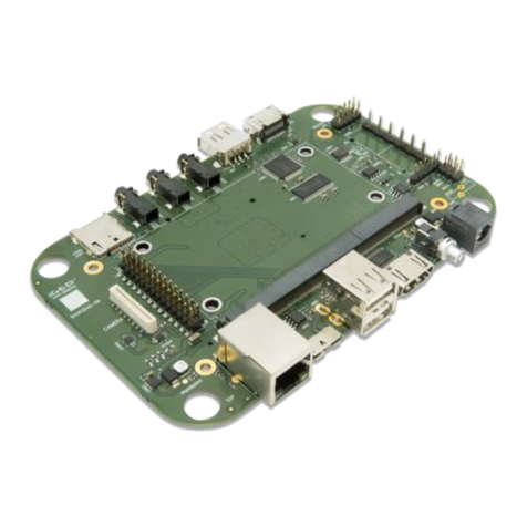
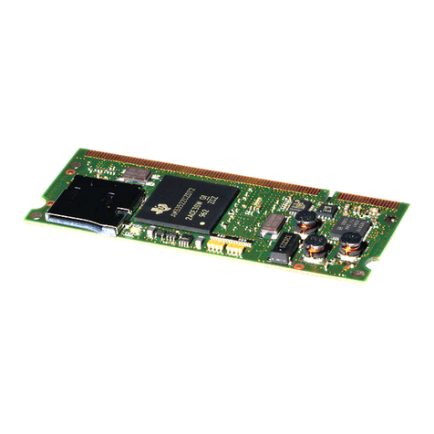
i-See IGEPv2 BOARD Quick user guide

ISEE
MANUAL
ISEE (
Integration Software & Electronics Engineering
)
Address: C/ Vallespir nº19 Planta 1 odulo 1
PostCode: 08173
City: Sant Cugat
Country: SPAIN
Telf. : +34.93.576.39.31
http://www.iseebcn.com
ISEE IGEPv2 EXPANSION
Hardware Reference anual
(Revision 01 - 24-Sep-2010)

IGEPv2 EXPANSION BOARD HARDWARE USER ANUAL
ISEE 2007 SL. All rights reserved, IGEP® is a registered trademark from ISEE 2007 SL. The following is
provided for informational purposes only.
DOCU ENT FRO ISEE 2007 S.L. 24-Sep-2010
2
CONTENTS
1
COPYRIGHT NOTICE ................................................................................ 5
2
WARRANTY ............................................................................................. 5
3
ISEE IGEP LINKS ..................................................................................... 6
4
ISEE IGEPv2 EXPANSION FEATURES .......................................................... 7
4.1
INTRODUCTION ................................................................................ 7
4.2
GENERAL SPECIFICATIONS ............................................................... 10
5
IGEPv2 CONNECTION.............................................................................. 16
6
CONNECTORS DESCRIPTION ................................................................... 19
6.1
J201 - POWER JACK .......................................................................... 20
6.2
J301 - POWERTIP 4.3” DATA CONNECTOR ........................................... 21
6.3
J302, J303 and J304 - SEIKO 7” CONNECTORS .................................... 22
6.4
J405 - ODE GS /GPRS SI CARD CONNECTOR ................................ 23
6.5
J404 - ODE GS /GPRS EXTERNAL ANTENNA CONNECTOR ................ 24
6.6
J501, J502 - VIDEO CO POSITE INPUTS CONNECTOR .......................... 25
6.7
J601 and J602 - UART1 HEADER CONNECTOR...................................... 26
6.8
J603 - RS232 HEADER CONNECTOR ................................................... 27
6.9
J604 - RS232 DB9 CONNECTOR ......................................................... 28
6.10
J703 - CAN BUS CONNECTOR ......................................................... 29
6.11
J801 - VGA CONNECTOR ................................................................ 30
6.12
J5 - CA ERA CONNECTOR .............................................................. 31
6.13
J990 - IGEPv2 EXPANSION CONNECTOR .......................................... 32
6.14
J960 - IGEPv2 EXPANSION CONNECTOR .......................................... 33
6.15
JA41 - IGEPv2 EXPANSION CONNECTOR .......................................... 34
6.16
JA42 - IGEPv2 EXPANSION CONNECTOR .......................................... 35
6.17
JC30 - IGEPv2 EXPANSION CONNECTOR .......................................... 36

IGEPv2 EXPANSION BOARD HARDWARE USER ANUAL
ISEE 2007 SL. All rights reserved, IGEP® is a registered trademark from ISEE 2007 SL. The following is
provided for informational purposes only.
DOCU ENT FRO ISEE 2007 S.L. 24-Sep-2010
3
7
ECHANICAL SPECIFICATION .................................................................. 37
8
BOARD REFERENCE ................................................................................ 38
9
LIST OF FIGURES ................................................................................... 39
10
CHANGELOG .......................................................................................... 41

IGEPv2 EXPANSION BOARD HARDWARE USER ANUAL
ISEE 2007 SL. All rights reserved, IGEP® is a registered trademark from ISEE 2007 SL. The following is
provided for informational purposes only.
DOCU ENT FRO ISEE 2007 S.L. 24-Sep-2010
4
VERSION CONTROL
REVISION
DATE ORIGIN DESCRIPTION
00 15/07/2010
PR Initial version
01 1/09/2010 PR Document release

IGEPv2 EXPANSION BOARD HARDWARE USER ANUAL
ISEE 2007 SL. All rights reserved, IGEP® is a registered trademark from ISEE 2007 SL. The following is
provided for informational purposes only.
DOCU ENT FRO ISEE 2007 S.L. 24-Sep-2010
5
1COPYRIGHT NOTICE
This document is copyrighted, 2010, by ISEE 2007 SL. All rights are reserved. ISEE
reserves the right to make improvements to the products described in this manual
at any time without notice. No part of this manual may be reproduced, copied,
translated or transmitted in any form or by any means without the prior written
permission of the original manufacturer. Information provided in this manual is
intended to be accurate and reliable. However, the original manufacturer assumes
no responsibility for its use, nor for any infringements upon the rights of third
parties which may result from its use.
2WARRANTY
Should this board not meet the specifications indicated in the User’s Guide, the
board may be returned within 30 days from the date of delivery for a full refund.
THE FOREGOING WARRANTY IS THE EXCLUSIVE WARRANTY MADE BY
SELLER TO BUYER AND IS IN LIEU OF ALL OTHER WARRANTIES,
EXPRESSED, IMPLIED, OR STATUTORY, INCLUDING ANY WARRANTY OF
MERCHANTABILITY OR FITNESS FOR ANY PARTICULAR PURPOSE.
The user assumes all responsibility and liability for proper and safe handling of the
goods. Further, the user indemnifies ISEE 2007 SL from all claims arising from the
handling or use of the goods. Due to the open construction of the product, it is the
user’s responsibility to take any and all appropriate precautions with regard to
electrostatic discharge.
EXCEPT TO THE EXTENT OF THE INDEMNITY SET FORTH ABOVE, NEITHER
PARTY SHALL BE LIABLE TO THE OTHER FOR ANY INDIRECT, SPECIAL,
INCIDENTAL, OR CONSEQUENTIAL DAMAGES.
ISEE 2007 SL currently deals with a variety of customers for products, and
therefore our arrangement with the user is not exclusive. ISEE assumes no liability
for applications assistance, customer product design, software performance, or
infringement of patents or services described herein.
Please read specifically, the Warnings and Restrictions notice in this manual prior to
handling the product. This notice contains important safety information about
temperatures and voltages. For additional information on IGEP environmental
and/or safety programs, please contact with ISEE (support@iseebcn.com).

IGEPv2 EXPANSION BOARD HARDWARE USER ANUAL
ISEE 2007 SL. All rights reserved, IGEP® is a registered trademark from ISEE 2007 SL. The following is
provided for informational purposes only.
DOCU ENT FRO ISEE 2007 S.L. 24-Sep-2010
6
No license is granted under any patent right or other intellectual property right of
ISEE covering or relating to any machine, process, or combination in which such
ISEE products or services might be or are used.
3ISEE IGEP LINKS
IGEP platform web site: http://www.igep.es
ISEE IGEP wiki: http://labs.igep.es
ISEE shop: https://shop.igep.es
ISEE Software Repositories: http://git.igep.es

IGEPv2 EXPANSION BOARD HARDWARE USER ANUAL
ISEE 2007 SL. All rights reserved, IGEP® is a registered trademark from ISEE 2007 SL. The following is
provided for informational purposes only.
DOCU ENT FRO ISEE 2007 S.L. 24-Sep-2010
7
4ISEE IGEPV2 EXPANSION FEATURES
4.1 INTRODUCTION
F gure 1 ISEE IGEPV2 EXPANSION
Description
Interfaces Modem GSM/GPRS based on TELIT GE865 module with SIMCARD
connector and external cable Antenna.
LCD and touch interface for 7.0 inch SEIKO LCD: 3 connectors (40pin FFC
for TFT interface + 4pin FFC for touch + 6pin FFC for LED backlight).
LCD and touch interface for 4.3 inch POWERTIP LCD: 40pin FFC for TFT
interface, touch and LED backlight).
VGA interface on D-SUB15 connector.
2 x video composite inputs on RCA connector. Video Decoder based on
TEXAS Video Decoder TVP5150.

IGEPv2 EXPANSION BOARD HARDWARE USER ANUAL
ISEE 2007 SL. All rights reserved, IGEP® is a registered trademark from ISEE 2007 SL. The following is
provided for informational purposes only.
DOCU ENT FRO ISEE 2007 S.L. 24-Sep-2010
8
Camera interface for e-con Systems e-CAM32_OMAP module.
CAN bus interface with 4 pin connector. CAN interface based on MICROCHIP
MCP2515 CAN controller.
LVDS video serializer (MAX9247) (Optional)
Serial port on DB9 connector
Electrical Supply Voltage from 5 VDC +-10% from IGEPv2 board or 5VDC through
Power Jack connector
Power consumption: from 260mA to 500mA
Note: The electrical design for the Power supply should be made ensuring it
will be capable of a peak current output of at least 2 A.
Connectors 1 x DB9 for serial RS232 interface
2 x RCA for video composite input
1 x DB15 for VGA interface
1 x SIMCARD connector for MODEM GSM/GPRS
1 x Terminal block 5mm 4 pin
4 x Header for IGEPv2 interface
Environmental
-40..+85 C temperature range / -25.. 80ºC / 0..70ºC
Indicators 1 x bicolor SMD led (green/red) for MODEM status
2 x bicolor SMD led (green/red) for CAN interface
WARNING: IGEPv2 EXPANSION CAN ONLY BE POWERED WITH
5VDC THROUGH J201 and J990 CONNECTORS
OR THE BOARD WILL BE DAMAGED!

IGEPv2 EXPANSION BOARD HARDWARE USER ANUAL
ISEE 2007 SL. All rights reserved, IGEP® is a registered trademark from ISEE 2007 SL. The following is
provided for informational purposes only.
DOCU ENT FRO ISEE 2007 S.L. 24-Sep-2010
9
F gure 2 IGEPv2 EXPANSION Top v ew
F gure 3 IGEPv2 EXPANSION Bottom v ew
The following sections provide more detail on each feature and components on the
ISEE IGEPV2 EXPANSION.

IGEPv2 EXPANSION BOARD HARDWARE USER ANUAL
ISEE 2007 SL. All rights reserved, IGEP® is a registered trademark from ISEE 2007 SL. The following is
provided for informational purposes only.
DOCU ENT FRO ISEE 2007 S.L. 24-Sep-2010
10
4.2 GENERAL SPECIFICATIONS
LCD Interface
IGEPv2 EXPANSION board can be directly connected to a SEIKO 7” LCD or to a
POWERTIP 4.3” LCD.
F gure 4 LCD v ew
IGEPv2 EXPANSION board integrates LCD backlight driver (Texas instruments
TPS61081) and touch screen controller (Texas instruments TSC2046), 4-wire touch
screen controller which supports a low-voltage I/O interface from 1.5V to 5.25V.
POWERTIP 4.3” LCD features:

IGEPv2 EXPANSION BOARD HARDWARE USER ANUAL
ISEE 2007 SL. All rights reserved, IGEP® is a registered trademark from ISEE 2007 SL. The following is
provided for informational purposes only.
DOCU ENT FRO ISEE 2007 S.L. 24-Sep-2010
11
SEIKO 7” LCD features:
Module size 165mm(W)x105.8mm(H)x(4.51)mm(t) (except FPC length)
Active area 152.4mm(W)x91.44mm(H)
Dot pitch 0.0635mmx0.1905mm
Weight (170) g typ.
Display size 7.0 inch
Number of pixels 800RGBx480 dots
Dot layout Vertical stripes
Interface 24bit Parallel RGB
DE interface mode (DCLK,DE)
SYNC interface mode (DCLK,HSYNC,VSYNC)
Number of colors 16,194,277 colors (6bit DAC + dithering)
Display mode TN Mode, Transmissive Mode, Normally White
Viewing angle(U/D/R/L) 55/65/70/70 (@CR10)
Drive method Dot inversion
Back Light Unit Bottom edge type, 24 LEDs(8Serial x 3)
Touch-Panel Film/Glass type
Surface treatment Anti glare type
Operating temperature From -20 to +70 °C (dry)
Storage temperature From -30 to +80 °C (dry)
MODEM GSM/GPRS
IGEPv2 EXPANSION board integrates a modem GS /GPRS for mobile
communication.
F gure 5 Modem v ew
GE865 is a small GS /GPRS Ball-Grid-Array BGA module with next feature:
•Quad-band EGSM 850 / 900 / 1800 / 1900 MHz
•GSM/GPRS protocol stack 3GPP Release 4 compliant
•Output power
oClass 4 (2W) @ 850 / 900 MHz
oClass 1 (1W) @ 1800 / 1900 MHz
•Control via AT commands according to 3GPP 27.005, 27.007
•Control via Remote AT commands

IGEPv2 EXPANSION BOARD HARDWARE USER ANUAL
ISEE 2007 SL. All rights reserved, IGEP® is a registered trademark from ISEE 2007 SL. The following is
provided for informational purposes only.
DOCU ENT FRO ISEE 2007 S.L. 24-Sep-2010
12
•Power consumption (typical values)
oPower off: ‹ 62 uA
oIdle (registered, power saving): 1.6 mA @ DRX=9
•Serial port multiplexer 3GPP 27.010
•TCP/IP stack access via AT commands
•Sensitivity:
o≤- 107 dBm (typ.) @ 850 / 900 MHz
o≤- 106 dBm (typ.) @ 1800 / 1900 MHz
•Extended temperature range
o-40°C to +85°C (operational)
o-40°C to +85°C (storage temperature)
•RoHS compliant
F gure 6 Tel t module v ew
VIDEO COMPOSITE INPUTS
IGEPv2 EXPANSION board integrates a Ultralow-Power NTSC/PAL/SECA Video
Decoder, Texas Instruments TVP5151.
The TVP5151 device is an ultralow-power NTSC/PAL/SECA video decoder.
Available in a space-saving 48-terminal PBGA package or a 32-terminal TQFP
package, the TVP5151 decoder converts NTSC, PAL, and SECA video signals to 8-
bit ITU-R BT.656 format. Discrete syncs are also available. The optimized
architecture of the TVP5151 decoder allows for ultralow power consumption. The
decoder consumes 138-mW power under typical operating conditions and consumes
less than 1 mW in power-down mode, considerably increasing battery life in
portable applications. The decoder uses just one crystal for all supported standards.
The TVP5151 decoder can be programmed using an I2C serial interface.
The TVP5151 decoder converts baseband analog video into digital YCbCr 4:2:2
component video.

IGEPv2 EXPANSION BOARD HARDWARE USER ANUAL
ISEE 2007 SL. All rights reserved, IGEP® is a registered trademark from ISEE 2007 SL. The following is
provided for informational purposes only.
DOCU ENT FRO ISEE 2007 S.L. 24-Sep-2010
13
Composite and S-video inputs are supported. The TVP5151 decoder includes one 9-
bit analog-to-digital converter (ADC) with 2× sampling. Sampling is ITU-R BT.601
(27.0 Hz, generated from the 27.000- Hz crystal or oscillator input) and is line
locked. The output formats can be 8-bit 4:2:2 or 8-bit ITU-R BT.656 with
embedded synchronization.
The TVP5151 decoder utilizes Texas Instruments patented technology for locking to
weak, noisy, or unstable signals. A Genlock/real-time control (RTC) output is
generated for synchronizing downstream video encoders.
Complementary four-line adaptive comb filtering is available for both the luminance
and chrominance data paths to reduce both cross-luminance and cross-
chrominance artifacts; a chrominance trap filter is also available.
Video characteristics including hue, brightness, saturation, and sharpness may be
programmed using the industry standard I2C serial interface. The TVP5151 decoder
generates synchronization, blanking, lock, and clock signals in addition to digital
video outputs. The TVP5151 decoder includes methods for advanced vertical
blanking interval (VBI) data retrieval. The VBI data processor slices, parses, and
performs error checking on teletext, closed caption, and other data in several
formats.
The TVP5151 decoder detects copy-protected input signals according to the
acrovision™ standard and detects Type 1, 2, 3, and colorstripe processes.
The main blocks of the TVP5151 decoder include:
•Robust sync detector
•ADC with analog processor
•Y/C separation using four-line adaptive comb filter
•Chrominance processor
•Luminance processor
•Video clock/timing processor and power-down control
•Output formatter
•I2C interface
•VBI data processor
•acrovision detection for composite and S-video

IGEPv2 EXPANSION BOARD HARDWARE USER ANUAL
ISEE 2007 SL. All rights reserved, IGEP® is a registered trademark from ISEE 2007 SL. The following is
provided for informational purposes only.
DOCU ENT FRO ISEE 2007 S.L. 24-Sep-2010
14
CAN BUS
IGEPv2 EXPANSION board integrates a Stand-Alone CAN controller with SPI
interface, ICROCHIP CP2515.
icrochip Technology’s CP2515 is a stand-aloneController Area Network (CAN)
controller that implements the CAN specification, version 2.0B. It is capable of
transmitting and receiving both standard and extended data and remote frames.
The CP2515 has two acceptance masks and six acceptance filters that are used to
filter out unwanted messages, thereby reducing the host CUs overhead. The
CP2515 interfaces with microcontrollers ( CUs) via an industry standard Serial
Peripheral Interface (SPI).
CP2515 features:
•Implements CAN V2.0B at 1 b/s:
-0 – 8 byte length in the data field
-Standard and extended data and remote frames
•Receive buffers, masks and filters:
-Two receive buffers with prioritized message storage
-Six 29-bit filters
-Two 29-bit masks
•Data byte filtering on the first two data bytes (applies to standard data
frames)
•Three transmit buffers with prioritization and abort features
•High-speed SPI Interface (10 Hz):
-SPI modes 0,0 and 1,1
•One-shot mode ensures message transmission is attempted only one time
•Clock out pin with programmable prescaler:
-Can be used as a clock source for other device(s)
•Start-of-Frame (SOF) signal is available for monitoring the SOF signal:
•Can be used for time-slot-based protocols and/or bus diagnostics to detect
early bus degradation
•Interrupt output pin with selectable enables
•Buffer Full output pins configurable as:

IGEPv2 EXPANSION BOARD HARDWARE USER ANUAL
ISEE 2007 SL. All rights reserved, IGEP® is a registered trademark from ISEE 2007 SL. The following is
provided for informational purposes only.
DOCU ENT FRO ISEE 2007 S.L. 24-Sep-2010
15
-Interrupt output for each receive buffer
-General purpose output
•Request-to-Send (RTS) input pins individually configurable as:
-Control pins to request transmission for each transmit buffer
-General purpose inputs

IGEPv2 EXPANSION BOARD HARDWARE USER ANUAL
ISEE 2007 SL. All rights reserved, IGEP® is a registered trademark from ISEE 2007 SL. The following is
provided for informational purposes only.
DOCU ENT FRO ISEE 2007 S.L. 24-Sep-2010
16
5IGEPV2 CONNECTION
IGEPv2 EXPANSION board is connected to IGEPv2 board by using J990, JA41, JA42,
JC30 and J960 headers. Just take a look on the figure below.
F gure 7 IGEPv2 and IGEPv2 EXPANSION bottom entry assembly
IGEPv2 board connectors:
J990: SA TEC TSW-114-15-F-D
JA41: SA TEC FTS-114-01-L-D
JA42: SA TEC FTS-110-01-L-D
JC30: SA TEC FTS-114-01-L-D
IGEPv2 EXPANSION connector:
J990: SA TEC HLE-114-92-L-DV-BE
JA41: SA TEC SF C-114-01-L-D
JA42: SA TEC SF C-111-01-L-D
JC30: SA TEC SF C-115-01-L-D

IGEPv2 EXPANSION BOARD HARDWARE USER ANUAL
ISEE 2007 SL. All rights reserved, IGEP® is a registered trademark from ISEE 2007 SL. The following is
provided for informational purposes only.
DOCU ENT FRO ISEE 2007 S.L. 24-Sep-2010
17
SAMTEC
FTS Serie
SAMTEC
SFMC Serie
SAMTEC
TSW Serie
SAMTEC
HLE Serie
BOTTOM ENTRY
SAMTEC
SFMC Serie
SAMTEC
FTS Serie
1.27mm
3.05mm
2.54mm
5,85mm
4.57mm
SAMTEC
FTS Serie
SAMTEC
SFMC Serie
SAMTEC
TSW Serie
SAMTEC
HLE Serie
BOTTOM ENTRY
SAMTEC
SFMC Serie
SAMTEC
FTS Serie
5.84mm
3.66mm
F gure 8 IGEPv2 Bottom entry assembly
F gure 9 IGEPv2 connector deta l

IGEPv2 EXPANSION BOARD HARDWARE USER ANUAL
ISEE 2007 SL. All rights reserved, IGEP® is a registered trademark from ISEE 2007 SL. The following is
provided for informational purposes only.
DOCU ENT FRO ISEE 2007 S.L. 24-Sep-2010
18
F gure 10 IGEPv2 connector deta l
F gure 11 IGEPv2 and IGEPv2 EXPANSION bottom entry assembly

IGEPv2 EXPANSION BOARD HARDWARE USER ANUAL
ISEE 2007 SL. All rights reserved, IGEP® is a registered trademark from ISEE 2007 SL. The following is
provided for informational purposes only.
DOCU ENT FRO ISEE 2007 S.L. 24-Sep-2010
19
6CONNECTORS DESCRIPTION
This section will guide you through the IGEPv2 EXPANSION connectors:
•J201 POWER JACK
•J301 POWERTIP 4.3” DATA CONNECTOR
•J302 SEIKO 7” DATA CONNECTOR
•J303 SEIKO 7” BACKLIGHT CONNECTOR
•J304 SEIKO 7” TOUCHSCREEN CONNECTOR
•J405 ODE GS /GPRS SI CARD CONNECTOR
•J404 ODE GS /GPRS EXTERNAL ANTENNA CONNECTOR
•J501, J502 VIDEO CO POSITE INPUTS CONNECTOR
•J601 UART1 HEADER CONNECTOR
•J602 UART1 JST CONNECTOR
•J603 RS232 HEADER CONNECTOR
•J604 RS232 DB9 CONNECTOR
•J703 CAN BUS CONNECTOR
•J801 VGA CONNECTOR
•J991 LVDS CONNECTOR
•J5 CA ERA CONNECTOR
•J990 IGEPv2 EXPANSION CONNECTOR
•J960 IGEPv2 EXPANSION CONNECTOR
•JA41 IGEPv2 EXPANSION CONNECTOR
•JA42 IGEPv2 EXPANSION CONNECTOR
•JC30 IGEPv2 EXPANSION CONNECTOR

IGEPv2 EXPANSION BOARD HARDWARE USER ANUAL
ISEE 2007 SL. All rights reserved, IGEP® is a registered trademark from ISEE 2007 SL. The following is
provided for informational purposes only.
DOCU ENT FRO ISEE 2007 S.L. 24-Sep-2010
20
6.1 J201 - POWER JACK
The J201 connector is a power jack for main 5 VDC power.
It is a switchcraft connector ref. RAS 722, Plug/ ating Plug Diameter 2.1mm ID,
5.5mm OD.
F gure 12 J200 deta l
WARNING: IGEPv2 EXPANSION BOARD CAN ONLY BE
POWERED WITH 5V DC.
The connector is located as shows the figure below.
F gure 13 J201 locat on
Other manuals for IGEPv2 BOARD
2
Table of contents
Other i-See Computer Hardware manuals
Popular Computer Hardware manuals by other brands

Cypress
Cypress CapSense CY8C20396 Specification sheet

SeaLevel
SeaLevel Ultra-SIO 3089 user manual

ekwb
ekwb EK-FC 780 GTX Ti DCII INSTALLATION AND MOUNTING MANUAL

CNC4PC
CNC4PC C11 user manual

Sony
Sony BKPF-292 Operation manual

Intel
Intel X3350 - Xeon 2.66 Ghz 12M L2 Cache 1333MHz FSB LGA775 Quad-Core... datasheet

Rimage
Rimage Producer III 6100 Brochure & specs

Rosewill
Rosewill RC-611 user manual

Lattice Semiconductor
Lattice Semiconductor LatticeMico GPIO manual

HP
HP Xw4600 - Workstation - 2 GB RAM installation instructions

AEB
AEB COBRA AEB510N Fitting Instructions and Warranty Workbook

Fuji Electric
Fuji Electric OPC-VG1-DIO instruction manual