North Wing Scout 912 User manual
North Wing S-LSA Maintenance Manual
Model: Scout 912
Version 3.2
Release date 04-16-2014
Page 1
Manufacturer: North Wing UUM, Inc.
103 Gala Ave
Chelan, Wa. 98816
USA
Phone : + 509-886-4605
Fax : + 509-886-3435
Website : www.ultrikes@northwing.com

North Wing S-LSA Maintenance Manual
Model: Scout 912
Version 3.2
Release date 04-16-2014
Page 2
Preface
The documents listed below are required for a complete S-LSA package for the North Wing
Scout 912 S-LSA. This document is the North Wing S-LSA Scout 912 Maintenance Manual
for Types Navajo and Apache. It describes the maintenance requirements and procedures for
the wing, carriage, engine, and propeller.
•Pilot’s Operating Handbook
•Rotax Owners Manual
•Rotax Maintenance (Compact Disk)
•Radio Manual – If Installed
•BRS Parachute Manual – If Installed
•Manuals for all installed instrumentation
North Wing S-LSA Maintenance Manual
Model: Scout 912
Version 3.2
Release date 04-16-2014
Page 3
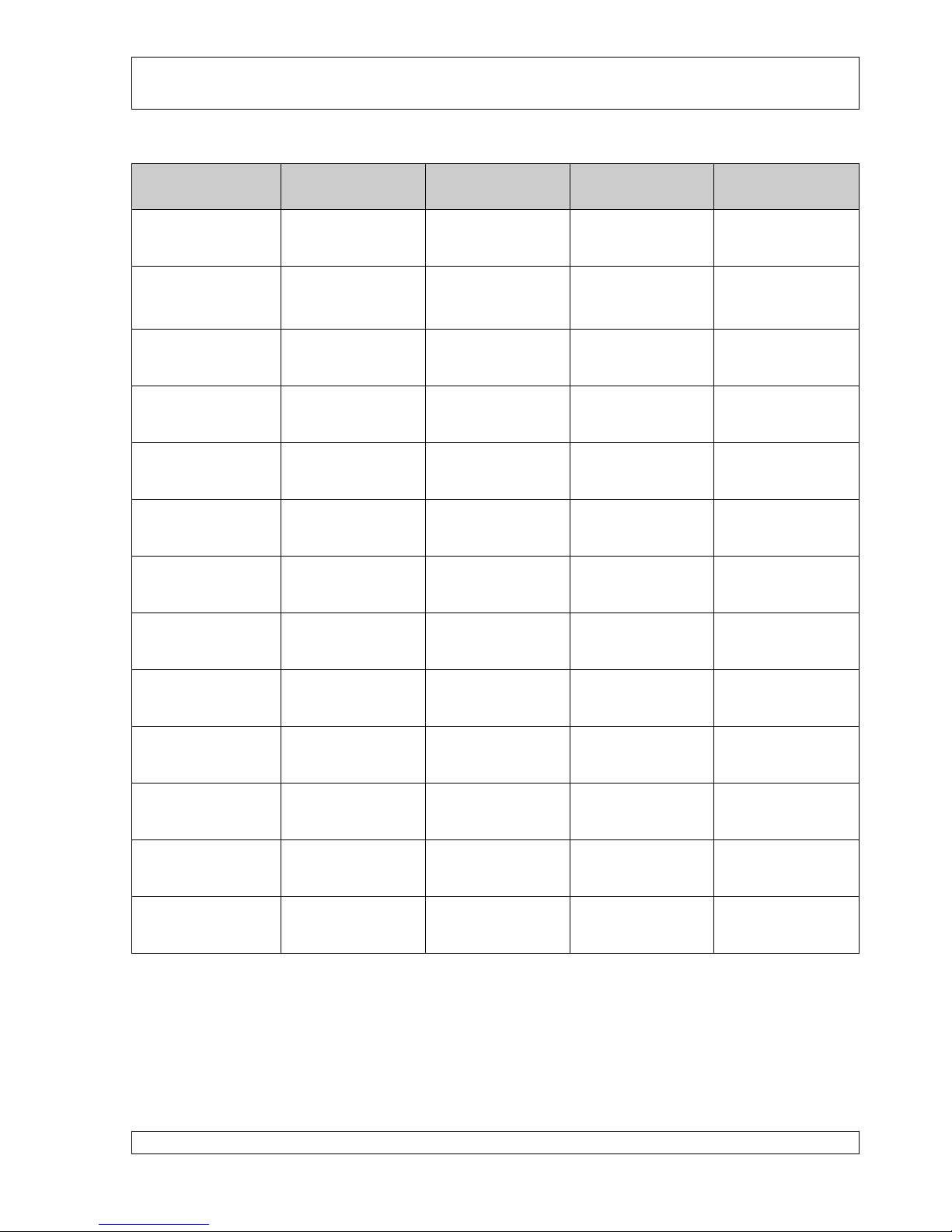
Manual Amendment Record Sheet
Amendment
Date
Affected
Sections
Affected
Pages
Date Inserted
Signature
Aug 15, 2009
Original Issue
Aug 15, 2011
All
V 2.2
Oct 10, 2012
V 3.0
Table 1 Amendment Record Sheet
NOTE:
North Wing’s manuals will be revised as necessary. Registered North Wing S-LSA owners
will be notified of any changes and directed to the North Wing web site
(<http://www.northwing.com>) for the applicable pages. The amended pages should be printed

North Wing S-LSA Maintenance Manual
Model: Scout 912
Version 3.2
Release date 04-16-2014
Page 4
and the prior page replaced in the folder as soon as possible. The amendment table should at
that time be updated with the appropriate details and date.

North Wing S-LSA Maintenance Manual
Model: Scout 912
Version 3.2
Release date 04-16-2014
Page 5
Table of Contents
1.0 Introduction ................................................................................................................... 7
1.1 Skills ............................................................................................................................ 7
1.2 Prohibited Maintenance and Alterations ..................................................................... 8
1.3 Tooling and Materials.................................................................................................. 9
1.4 Service Difficulties and Errors .................................................................................... 9
1.5 Format........................................................................................................................ 10
1.6 Mandatory Service Bulletins ..................................................................................... 10
2.0 General Information ................................................................................................... 11
2.1 Specifications ............................................................................................................ 11
2.1.1 Carriage ................................................................................................................. 11
2.1.2 Engine and Related Systems ................................................................................. 12
2.1.3 Fuel System ........................................................................................................... 12
2.1.4 Cooling System ..................................................................................................... 12
2.1.5 Propeller ................................................................................................................ 13
2.1.6 Electrical System ................................................................................................... 13
2.1.7 Instrumentation System ......................................................................................... 13
2.1.8 Torque Specifications and Securing...................................................................... 14
2.2 Weight and Loading for Quest GT5.......................................................................... 17
2.3 Weight and Loading for Mustang 3........................................................................... 18
2.4 Ground Handling ....................................................................................................... 19
2.4.1 Moving .................................................................................................................. 19
2.4.2 Parking and Tie Down........................................................................................... 20
2.4.3 Lifting .................................................................................................................... 20
2.5 Lubrication ................................................................................................................ 20
2.6 Replacement Parts ..................................................................................................... 20
3.0 Inspections.................................................................................................................... 22
3.1 Inspection Procedure ................................................................................................. 22
3.2 Inspection Checklists................................................................................................. 24
4.0 Maintenance and Repairs ........................................................................................... 31
4.1 Maintenance Tasks .................................................................................................... 31
4.2 Wing Maintenance: Quest GT5 Wing, MP2-15, Mustang 3..................................... 34
4.3 Carriage Maintenance................................................................................................ 34
4.3.1 Cleaning Exterior................................................................................................... 34
4.3.2 Remove Rear Wheel Pants .................................................................................... 34
4.3.3 Replace Rear Tire .................................................................................................. 36
4.3.4 Replace Rear Wheel Bearing................................................................................. 39
4.3.5 Hegar Brake System: Replace Pads, Calipers, and Disc; Bleed/Adjust Brakes.... 39
4.3.6 MATCO Brake System: Replace Pads, Calipers, Bleed/Adjust Brakes ............... 43
4.3.7 Replace Front Tire................................................................................................. 44
4.3.8 Reposition Front Fork Assembly........................................................................... 46
4.3.9 Repair/Replace Front Fork Assembly ................................................................... 47
4.3.10 Repair/Replace Seat Frame and Front Seat Backrest ............................................ 48
4.3.11 Replace Main Dual Mast ....................................................................................... 51
4.3.12 Replace Seat Belts ................................................................................................. 52

North Wing S-LSA Maintenance Manual
Model: Scout 912
Version 3.2
Release date 04-16-2014
Page 6
4.3.13 Replace Mast Lift Cylinder ................................................................................... 53
4.3.14 Repair Radiator or Hose Leak ............................................................................... 54
4.3.15 Remove and Repair Scout 912 Fairing.................................................................. 55
4.4 Fuel System Repairs .................................................................................................. 56
4.4.1 Replace Fuel Lines ................................................................................................ 57
4.4.2 Replace Fuel Filter ................................................................................................ 57
4.4.3 Replace Fuel Tank................................................................................................. 58
4.4.4 Replace Fuel Tank Drain Valve ............................................................................ 59
4.4.5 Calibrate Fuel Gage............................................................................................... 59
4.5 Electrical System ....................................................................................................... 63
4.5.1 Replacing Battery .................................................................................................. 67
4.5.2 Checking and Replacing Voltage Regulator ......................................................... 68
4.5.3 Testing and Replacing Magneto Switches ............................................................ 69
4.5.4 Testing and Replacing Master Switch................................................................... 71
4.5.5 Replacing Hot Box ................................................................................................ 72
4.5.6 Replacing Starter Solenoid .................................................................................... 72
4.5.7 Connecting 12 Volt Power to Auxiliary Equipment ............................................. 73
4.6 Engine........................................................................................................................ 74
4.6.1 Changing engine oil............................................................................................... 74
4.6.2 Changing spark plugs ............................................................................................ 74
4.7 Ballistic Recovery System (BRS Parachute)............................................................. 74
Appendix A: Princeton Fuel Level Sending Unit ................................................................. 77
Princeton Level Sensor Description ...................................................................................... 78
Princeton Level Sensor Installation....................................................................................... 79
Princeton Level Sensor Calibration....................................................................................... 80

North Wing S-LSA Maintenance Manual
Model: Scout 912
Version 3.2
Release date 04-16-2014
Page 7
1.0 Introduction
This manual contains factory recommended procedures and instructions for ground handling,
inspection, servicing and maintaining the North Wing S-LSA aircraft. The procedures
described are to be used in conjunction with the appropriate Airworthiness Authority of the
country of registration. Any airworthiness requirement published by the national authority
takes precedence over this manual.
1.1 Skills
Maintenance of any aircraft requires a skill level commensurate with the specific maintenance
task. This manual identifies the skill level for each maintenance task according to the
following industry standard certification levels:
Owner:
Tasks that can be expected to be completed by a responsible and skilled owner who holds a
pilot certificate but who has not received any specific authorized training. This includes all
items in Part 43 appendix A – Preventative maintenance.
LSA Repairman – Inspection:
Items that can be expected to be completed on an E-LSA by a responsible owner who holds an
FAA repairman certificate (light sport aircraft), with an inspection rating or equivalent.
Abbreviation: LR-I
LSA Repairman - Maintenance :
Items that can be expected to be completed on a S-LSA by a responsible individual who holds
a FAA repairman certificate (light sport aircraft) with a maintenance rating or equivalent from
an FAA approved 104 hour course on Weight Shift Control. Abbreviation: LR-M
A&P:
Items that can be expected to be completed by a responsible individual who holds a mechanic
certificate with airframe or power plant ratings, or both, or equivalent.
Task Specific:
Items that can be expected to be completed by a responsible individual who has received task
specific training from North Wing to perform the task.
For those functions and tasks identified as suitable for an owner to perform, a sound
understanding of mechanical systems, and good experience with the necessary tools and
procedures is required. A lack of complete understanding of any task may render the aircraft
un-airworthy and unsafe. Assessment and judgment of the condition of each individual
component is required, which necessitates a sound understanding of the purpose of each
component in the system. If there are any doubts regarding the required and appropriate

North Wing S-LSA Maintenance Manual
Model: Scout 912
Version 3.2
Release date 04-16-2014
Page 8
maintenance, then the safety of the aircraft may be jeopardized in continuing with self
maintenance. In this situation a North Wing-approved repair facility should be contacted for
the correct procedures and or servicing.
All maintenance and repairs must be logged in the appropriate Airframe, Engine, Propeller, or
Wing log book and signed by the person who performed the repair. Although it is
recommended, it is not required to maintain four separate log books as indicated above.
However, any maintenance on any of the four systems must be logged in a maintenance log
book and signed by the person performing the task.
1.2 Prohibited Maintenance and Alterations
This manual addresses only “Line” maintenance functions and tasks that can reasonably be
performed by a responsible and skilled person as described above. It does not address any
“Heavy” maintenance tasks such as the removal of the engine cylinder heads, gear box, or
electrical end of the engine block. For all required maintenance on the Rotax 912, refer to the
Rotax engine manual provided with your North Wing S-LSA trike. For heavy repairs as
mentioned above, consult a factory trained and certified Repairman Maintenance technician
for Rotax engines. A list of Rotax repair stations can be found on-line, or contact your North
Wing dealer.
Although “repairs” may be authorized for nearly all components, ”alterations” to the following
items beyond those specifically identified herein are strictly prohibited due to their critical
safety role:
oairframe assembly
obackframe
omast assembly
oseat frame
oroot tube
osteering assembly
opivot block assembly
owing ribs, cables, struts, crossbar, or control frame
obolt sizes or lengths
North Wing S-LSA Maintenance Manual
Model: Scout 912
Version 3.2
Release date 04-16-2014
Page 9
WARNING
THE INFORMATION IN THIS MANUAL NEEDS TO BE FOLLOWED, AND IT IS NOT
ACCEPTABLE TO MAKE CHANGES TO THE MATERIALS AND OR PHYSICAL
FEATURES OF THIS AIRCRAFT. IN PARTICULAR THE GRADES OF BOLTS THAT
HAVE BEEN UTILIZED IN THE MANUFACTURE OF THIS AIRCRAFT ARE
CRITICAL FOR ITS CONTINUING AIRWORTHINESS. NEVER REPLACE BOLTS
WITH ANY OTHER SIZE OR GRADE. GRADE 8 BOLTS ARE NOT
INTERCHANGEABLE WITH AIRCRAFT (AN) GRADE BOLTS. THE FATIGUE
CHARACTERISTICS OF AIRCRAFT GRADE BOLTS ARE SUPERIOR TO OTHER
BOLTS AND ALLOW LONGER SAFE SERVICE LIFE UNDER CYCLIC LOADS LIKE
THOSE EXPERIENCED IN AIRCRAFT. THE LENGTH OF BOLT IS IMPORTANT. IF A
SHORTER BOLT IS USED THE THREAD MAY ENCROACH ON THE LOAD BEARING
AREA, WHICH INCREASES THE STRESSES EXPERIENCED BY IT.
1.3 Tooling and Materials
In general, all maintenance described herein is capable of being done with standard mechanics
tools. However, since the Rotax engine is built in Austria, a set of metric open end, box,
sockets, and hex wrenches may be needed. The only tools that might be considered somewhat
special or unusual needed for the maintenance described in this manual are the following:
•Low range torque wrench capable of up to 230 inch pounds of torque with both metric
and English size sockets
•High range torque wrench capable of up to 50 foot-pounds of torque with both metric
and English size sockets
•Bettsometer for testing wing fabric strength
•Syringe with capacity of at least 4 ounces for bleeding the hydraulic brakes
•Propeller pitch gauge
•Safety wire twisting pliers and safety wire
•Air pump
•Lubricants and other liquid/paste materials required by Rotax
•Loctite 243
•Anti-seize lubricant
•Plastic wire ties of various sizes
•Oil resistant paste thread sealer (teflon tape should never be used on fuel or oil fittings)
Other items may be required that are not on this list.
1.4 Service Difficulties and Errors
Any service difficulties, errors in this manual, or product defects should be reported to North
Wing via the web site, fax, or telephone. Corrections will be made as appropriate and reported
on the North Wing UUM Inc. web site.
North Wing S-LSA Maintenance Manual
Model: Scout 912
Version 3.2
Release date 04-16-2014
Page 10
1.5 Format
Chapter 2 provides general information useful for various maintenance activities. Chapters 3
and 4 address inspection and maintenance procedures for the major subsystems and equipment
groups that comprise the North Wing aircraft. The Table of Contents provides a good guide
to the sections needed for any line item repair, many or which can be performed by the owner.
For heavy maintenance, such as rebuilding the engine, the owner is referred to the Rotax
manual and to expert repair stations.
The information in this manual is based on the data that was available at the time of its
publication. The latest amendments to this manual will be issued on the North Wing website in
PDF format. This should be printed out and added to the manual. Therefore it is important that
operators keep a regular check on the website for any amendments that have been made. If any
errors or omissions are found in this manual please advise the factory.
1.6 Mandatory Service Bulletins
AS THE SERVICE HISTORY OF THE AIRFRAME EVOLVES NORTH WING WILL
PERIODICALLY ISSUE MANDATORY SERVICE BULLETINS WHICH DETAIL ANY
CHANGES TO THE MAINTENANCE MANUALS, PILOT’S OPERATING HANDBOOK,
OR ANY OTHER IMPORTANT DETAILS.
THE WEB ADDRESS FOR SERVICE BULLETINS IS:
HTTP://WWW.NORTHWING.COM
IT IS THE RESPONSIBILITY OF THE OPERATOR TO KEEP UP TO DATE WITH ANY
ROTAX DIRECTIVES THROUGH THE ROTAX WEBSITE.

North Wing S-LSA Maintenance Manual
Model: Scout 912
Version 3.2
Release date 04-16-2014
Page 11
2.0 General Information
2.1 Specifications
2.1.1 Carriage
Standard Configuration:
Material:
•Root tube: 2” x 3” rectangular 6061 aluminum tube
•Seat frame: 1¼inch outside diameter 6061 aluminum tube
•Welded steel lower back frame
•Welded steel dual mast
•11/4 inch diameter 6061-T6 aluminum nose tube with machined aluminum
fittings at both ends for attachment
•1’ x 2” sq. steel tube horizontal engine support
•Engine off set for P-factor adjustments
•Powder coated or plated finish on all structural tubes
•Tires: Tubeless 15x6.00-6 (actual tire OD 13.5”) 4 ply. Recommended
pressure 20 psi
•Rear wheel hydraulic brakes
•Wheel pants with fin (needed for 912 with full fairing- “Apache”)
Dimensions:
•Length from fairing nose to propeller: 112 inches (Apache)
•Length from carriage root tube to propeller: 108 inches (Navajo)
•Width (side to side outside of tires): 73 inches
•Width (side to side outside of wheel pants: 75 inches
•Total height with wing level 108 inches
•Wheel base (rear axle to front axle):
oin short setting 66.5 inches
oin long setting 69.0 inches
Optional Equipment:
•Body fairing (Apache): Fiberglass -gel coat finish (Red, Yellow or Black)
•Optional Tires: (sand tires) 8.00-6 (actual tire OD is 17.5”) Recommended
pressure 20 psi (NOT RECOMMENDED FOR FASTER WINGS SUCH AS
QUEST GT5 WING)
•Wheel pants: Navajo-Fiberglass resin with matching color to body fairing
•Intercom (helmet) system
•Ballistic Recovery System with single or dual actuating handle

North Wing S-LSA Maintenance Manual
Model: Scout 912
Version 3.2
Release date 04-16-2014
Page 12
2.1.2 Engine and Related Systems
Standard Configuration:
•Rotax 912 Dual carburetor and dual ignition (DCDI)
•Emergency set of magneto switches for instructor
•Dual Bing carburetors
•Remote choke operation
•Capacitor Discharge Dual ignition system
•Stainless steel dual exhaust
•North Wing custom radiator system
•80 hp @ 5800 rpm; 75.9ft.lbs max torque @ 4800 rpm
•Maximum RPM: 5800 rpm
•Gear drive 2.27:1 with electric starter
•Water cooled Heads
•Fuel pump driven from drive box
•Spark plugs: NGK DCPR7E
Optional Equipment:
•External alternator
•Carburetor heat
•Ultra-quiet dual exhaust
2.1.3 Fuel System
Standard Configuration:
•16 gallon translucent polymer fuel tank
•Electric fuel gauge with panel display
•Engine driven fuel pump
•See-through in-line fuel filter
•Cable driven dual throttle actuators (from front seat, right foot and hand
throttle)
•Remote cable driven choke actuator from front seat
Optional Equipment:
•Grand Rapids EIS fuel flow monitor
2.1.4 Cooling System
Standard Configuration:
•Radiator shock mounted on the right side
•Coolant reservoir with 8 psi pressure cap
•Coolant: 50/50 Ethylene Glycol/Water mix or Evans Waterless coolant
•Coolant capacity: 1 gal US

North Wing S-LSA Maintenance Manual
Model: Scout 912
Version 3.2
Release date 04-16-2014
Page 13
2.1.5 Propeller
•Warp 3 blade 68” carbon fiber propeller
•Pitch set by gauge
Optional Equipment
•Aerolux 69” 3 blade with pitch marking inscribed
2.1.6 Electrical System
Standard Configuration:
•12 volt starter with key operation from the front seat
•Hot Box wiring center or relay/fuse box.
•Regulated Lighting Coils (250Watts AC @ 5800rpm)
•Voltage regulator (Ducati on 912)
•12 volt 18 amp-hour battery
•Fusing integral to Hot Box or relay/fuse box.
•Strobe light: mounted at rear below BRS mount
•Electronic Instrument System
Optional Equipment:
•Navigation position lights (red/green/white mounted on wing tips for flight
after civil twilight)
•In-dash Radio
•ATC Transponder with encoding altimeter
2.1.7 Instrumentation System
Standard Configuration:
•Electronic Instrument System (EIS) Standard Functions
1. Alarm and limit setting
2. Exhaust gas temperature 2 cylinders
3. Water temperature
4. Engine RPM
5. Total engine run time
6. Flight time for current flight
7. Altitude
8. Rate of climb/decent
•Analog gauges for the following instruments:
1. Airspeed
2. Fuel tank level
Optional Equipment:
•MGL –Horizon engine instrument
•Transponder
•Fuel Flow meter- EIS Option

North Wing S-LSA Maintenance Manual
Model: Scout 912
Version 3.2
Release date 04-16-2014
Page 14
2.1.8 Torque Specifications and Securing
Before any fastener is torqued to specifications, it is important to assure at least one full thread
of the bolt will extend beyond the nut when tightened. If the bolt does not extend at least that
far, the bolt thread itself may fail if tightened to specifications.
Not all bolt connections have specific torque requirements. There are three basic types of
bolt/nut connections that are addressed in the table below:
1. Normal bolt/nut fasteners
2. Nylock fasteners
3. Castle nut fasteners
Normal bolt/nut fasteners will have torque specifications listed in the table below.
Nylock nuts are used for many applications. Some of those applications do not require
specific torque values while others do. For those applications where the bolt is exposed to
only shear forces, the nut should be tightened until there is no free play in the connection, or
all gap is eliminated between the nut and the fixtures being bolted together, then tightened
another quarter to half turn. These applications are referred to as “Snug” connections in this
manual. The limiting factor in the tightening of most Nylock applications on tubing is to avoid
distorting the tubing circular shape. For those applications where significant torque should
be used, a recommended torque is specified in the table below.
Castle nut fasteners are used for applications where the bolt is exposed only to shear stresses
and does not experience any longitudinal tensile stresses. The purpose of the castle nut is to
allow easy assembly and disassembly without the need for tools. Castle nuts must be secured
in place with a safety pin or ring of any appropriate design. For these fasteners some gap
between the bolt or nut under-side surface and the material being fastened is acceptable but
should not be excessive. That is, the nut should be tightened to remove all visible gap and
then adjusted to the nearest hole alignment for the safety pin. These types of attachments are
referred to in this manual as simply “Secured” as opposed to “Torqued” or “Snug”.
Some fasteners must be secured from loosening using either safety wire, ring safeties, or pin
safeties. The table below indicates which type of fastener should be used in each application,
the type of safety recommended for each where applicable, and the associated torque where
appropriate.
North Wing S-LSA Maintenance Manual
Model: Scout 912
Version 3.2
Release date 04-16-2014
Page 15
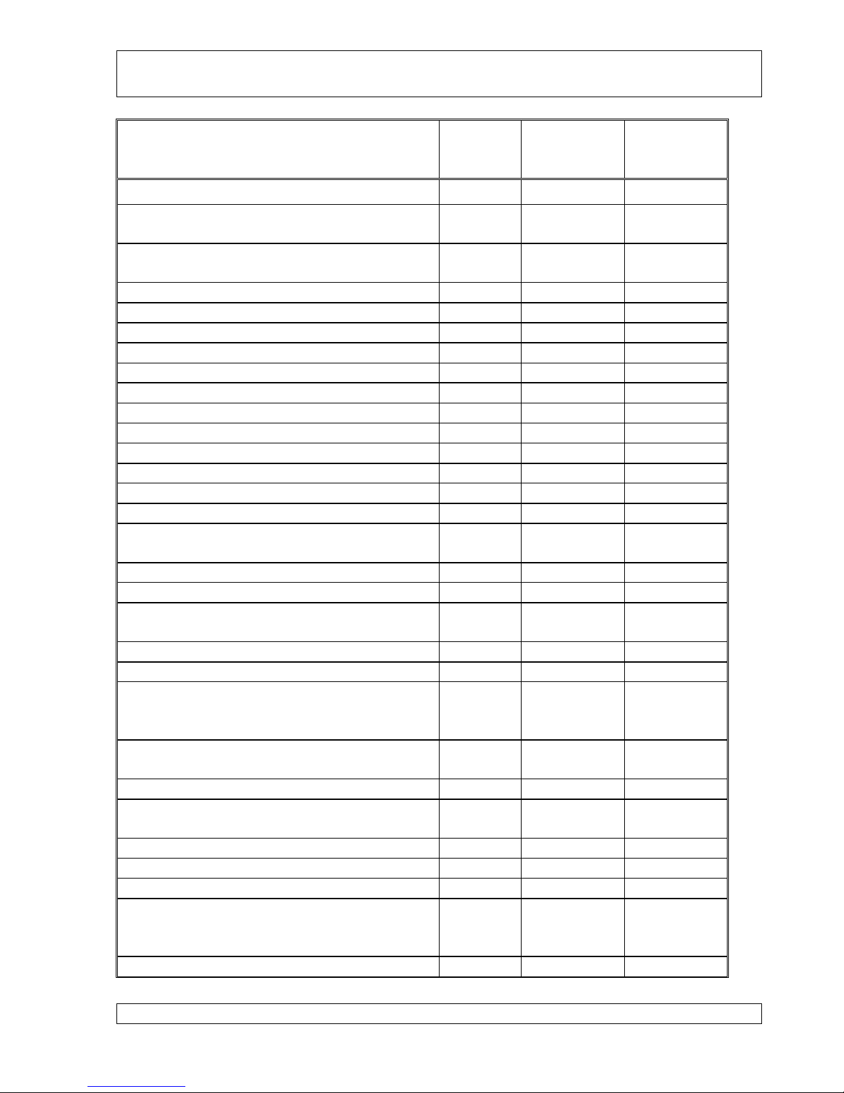
Location
Size
Securing
Method
Torque
Value
(inch lbs)
Carriage:
Rear wheel axle nut
5/8”
Nylock
Snug less1/4
turn
Front wheel axle nut
5/8”
Nylock
Snug less 1/4
turn
Split wheel rim bolts
1/4”
Nylock
Snug
Axle to backframe bolts thru fiberglass rods
1/4”
Nylock
Snug
Seat frame upper/lower joint bolts
1/4”
Nylock
Snug
Lower lift cylinder bracket attachment
1/4”
Nylock
Snug
Seat frame to backbone attachment
1/4”
Nylock
Snug
Seat frame to main base tube
1/4”
Nylock
Snug
Mast connection bolts
5/16”
Nylock
Snug
Mast pivot bolts
5/16”
Nylock
Snug
Nose tube upper bolt/nut
1/4”
Castle/pin
Secured
Nose tube lower bolt/nut
1/4”
Castle/pin
Secured
Engine:
Engine mount bolts
10mm
Castle nut &
cotter pin
310
Exhaust flange bolts
8mm
Lock nut
106
Carburetor boot hose clamps
Snug
All others
See Rotax
manual
Electrical System:
Spark plugs
12mm
Heat
conduction
compound
177
Battery hold down plate
3/16”
Wing nut &
cotter pin
Secured
Cable clamp to battery post
3/16”
Lock washer
Snug
Hot Box or relay/fuse box connections
6-32
Snug + 1/2
turn
Cooling System:
Radiator mounting bolts
5/16”
Lock washer
Snug
Hose clamps
As required
to prevent
leaking
North Wing S-LSA Maintenance Manual
Model: Scout 912
Version 3.2
Release date 04-16-2014
Page 16
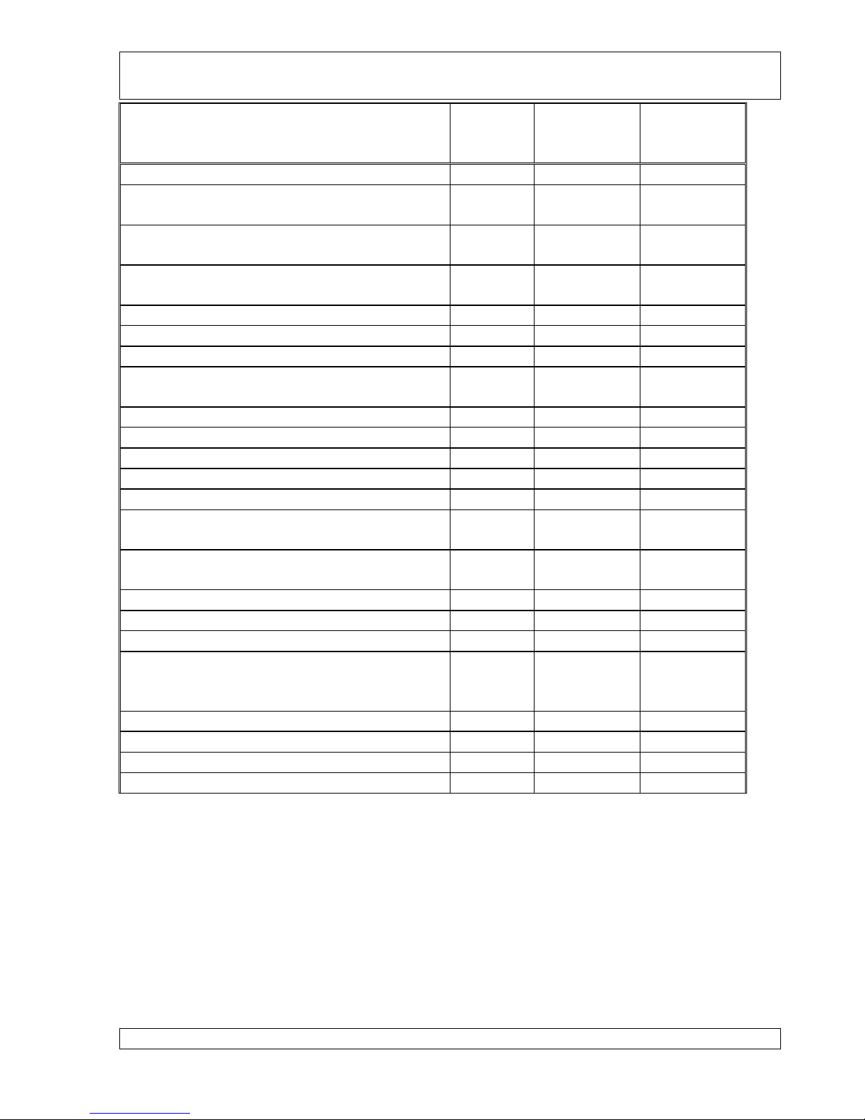
Location
Size
Securing
Method
Torque
Value
(inch lbs)
Wing:
Base tube left side connections to corner
bracket
1/4”
Castle
Snug
Base tube right side connections to corner
bracket
1/4”
Nylock
Snug
Strut attachment bracket on downtube(both
sides)
1/4”
Castle
Secured
Strut attachment fitting on ends of struts
1/4”
Nylock
Snug
Control frame apex bolt
Nylock
Snug
Front/rear wire tang attachment to downtube
1/4”
Nylock
Snug
Pivot block assemble top bolt
3/8”
Castle +
safety pin
Snug
Pivot block assemble middle two bolts
3/8”
Nylock
Snug
Pivot block assemble bottom bolt
3/8”
Nylock
Snug
Nose plate to leading edge bolts
¼”
Nylock
Snug
Crossbar plate to crossbar bolts
¼”
Nylock
Snug
Nose wire catch assemble to keel tube
¼”
Nylock
Snug
Crossbar to leading edge attachment bolts
3/8” eye
bolt
Castle safety
wired
Secured
Attachment bracket on leading edge for
crossbar
¼”
Nylock
Snug
Sprog attachment to LE bracket
¼”
Nylock
Snug
Propeller: Warp
Mounting bolts to gear box plate
8mm
Safety wire
or lock nut
on back
175
Individual blade hold down bolts
6mm
Nylock
120
Propeller: Aerolux
Mounting bolts to gear box plate
Nylock
130
Individual blade hold down bolts
Nylock
45
North Wing S-LSA Maintenance Manual
Model: Scout 912
Version 3.2
Release date 04-16-2014
Page 17
2.2 Weight and Loading for Quest GT5
Apache Navajo
Max. take off weight 1060 lbs 1060 lbs
Empty Weight 555 lbs 525 lbs
Wet trike weight (with 16.25 gal fuel) 655 lbs 625 lbs
Total max crew weight w/full fuel 405 lbs 435 lbs
Front seat load range: 120 – 280 lbs 120 – 280 lbs
Rear seat load range: 0 – 280 lbs 0 – 280 lbs
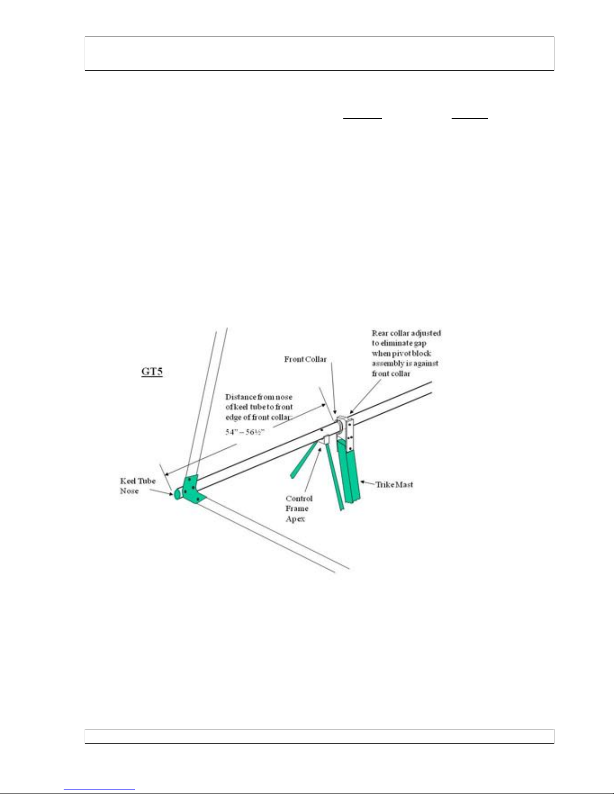
The trike center of gravity (CG) is adjusted by sliding the pivot block retaining collars forward
and aft to the desired position. The range is measured by the distance from the front edge of
the front retaining collar to the front tip of the keel tube (not nose bracket). See the sketch
below.
In its forward most position, the front collar is up against the control frame apex. This is a
distance of 54” from the front of the keel tube. The pivot block assembly may be moved
rearward a maximum of 2.5” resulting in a measurement from the keel tube tip to the front
collar of 56.5”.
North Wing S-LSA Maintenance Manual
Model: Scout 912
Version 3.2
Release date 04-16-2014
Page 18
2.3 Weight and Loading for Mustang 3
Apache Navajo
Max. take off weight 1060 lbs 1060 lbs
Empty Weight 550 lbs 520 lbs
Wet trike weight (with 16.25 gal fuel) 650 lbs 620 lbs
Total max crew weight w/full fuel 410 lbs 440 lbs
Front seat load range: 120 – 280 lbs 120 – 280 lbs
Rear seat load range: 0 – 280 lbs 0 – 280 lbs
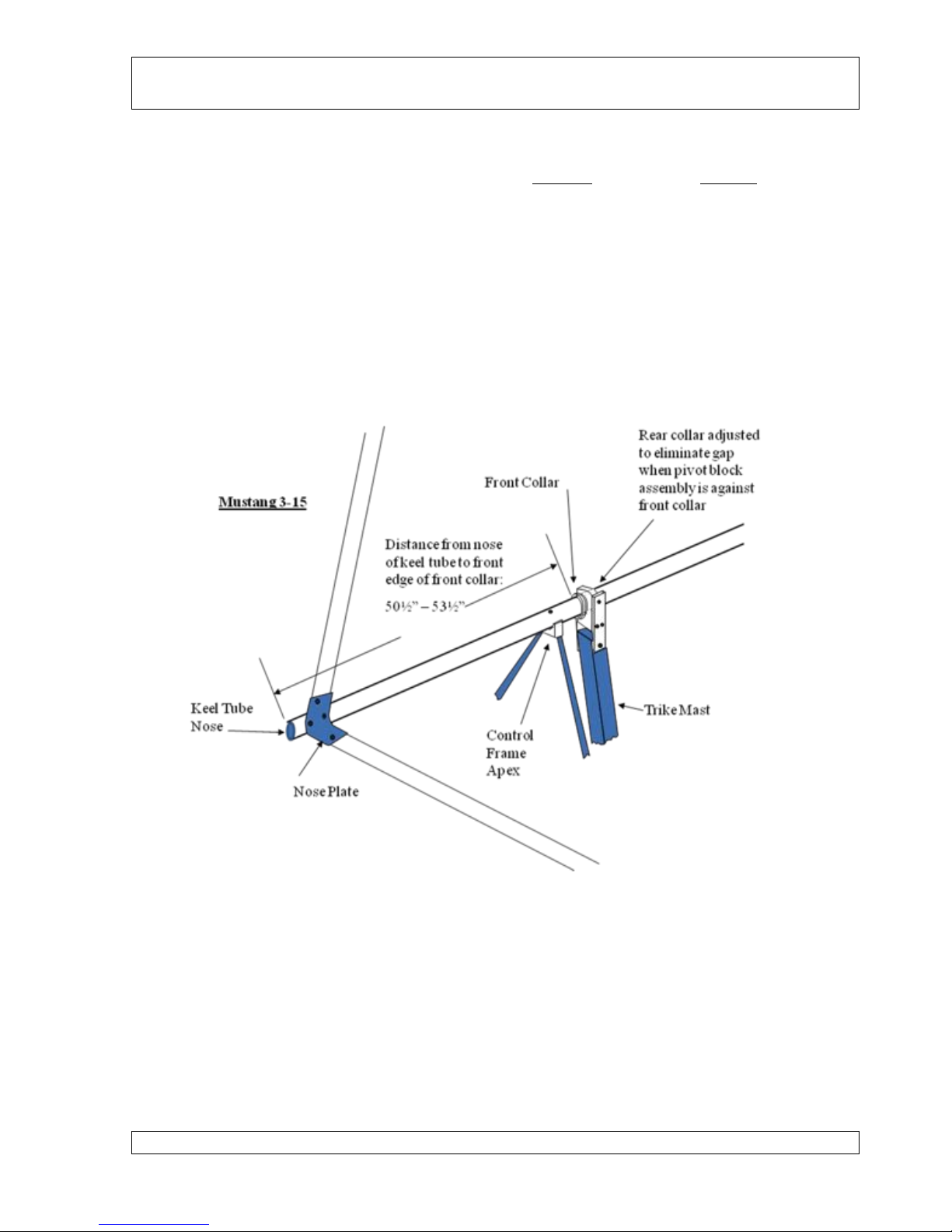
The trike center of gravity (CG) is adjusted by sliding the pivot block retaining collars forward
and aft to the desired position. The range is measured by the distance from the front edge of
the front retaining collar to the front tip of the keel tube (not nose bracket). See the sketch
below.
In its forward most position, the front collar is up against the control frame apex. This is a
distance of 50 ½” from the keel tube tip. The pivot block assembly may be moved rearward a
maximum of 3” resulting in a measurement from the keel tube tip to the front collar of 53½”.
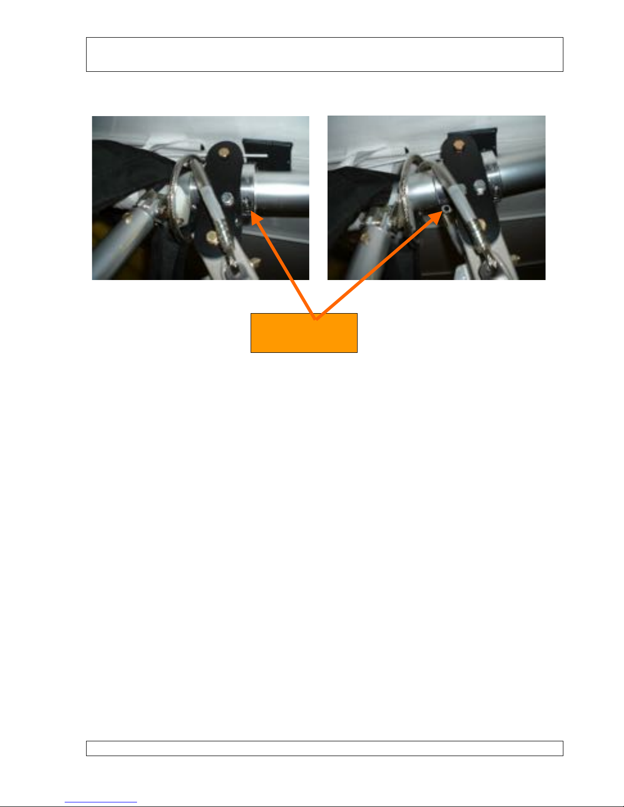
The hang point is changed by loosening the split collar bolts evenly about 3 turns each with a
¼” Allen wrench. This should be enough to slide the collars to the desired position. Note! It
is helpful to have the wing nose up when moving the hang point forward and the wing nose
down when moving the hang point rearward. This will allow the wing to slide in the pivot
block assembly with very little manual force. Retighten the collar bolts evenly. DO NOT
North Wing S-LSA Maintenance Manual
Model: Scout 912
Version 3.2
Release date 04-16-2014
Page 19
tighten just one collar bolt completely and then the other. This will distort and possibly
damage the keel tube.
Hang Point Moved Full Forward Hang Point Moved Full Back
Caution:
For loads up to and greater than 850 lbs. the cg must be no further back than the rear
measurement stated.
2.4 Ground Handling
Care must be taken for several reasons in maneuvering the trike on the ground for
maintenance:
1. Avoid overstressing the pivot block assembly that connects the trike to the wing
2. Avoid causing the trike to flip onto the propeller by lifting the nose too high
3. Avoid wear of the base tube due to rubbing against the nose tube
4. Avoid wing tip damage due to scraping the ground or hitting objects
2.4.1 Moving
To safely move the trike with the wing attached, use the following procedure:
1. Anchor base tube securely to carriage either with a bungee or strap holding the base
tube against the nose tube, or by using the seat belts to hold the base tube against the
seat. Be sure the wing is tilted at least 20°into the wind if trike is to be moved outside.
2. Release the parking brake
3. Confirm that the ignition magneto switches are off.
4. Push on the propeller near the hub, steering left and right by pushing on one side of the
propeller harder than the other side. It is quite easy to steer the trike in the desired
direction using this method.
Collar Bolts
¼” Allen wrench
North Wing S-LSA Maintenance Manual
Model: Scout 912
Version 3.2
Release date 04-16-2014
Page 20
2.4.2 Parking and Tie Down
Never leave the trike outside without securing both the wing and the trike. Be sure the wing is
tilted into the wind, and secure the parking brake. For wind conditions greater than 5mph, the
wing should be secured using the tie down straps located inside the wing at the crosstube-to-
leading edge connection zipper. Position the wing at 90°to the wind direction so that the wind
tends to press the lowered wing down further. Anchor owner supplied straps to the tie down
straps inside the wing so as to hold this angle into the wind.
2.4.3 Lifting
The nose of the trike can be lifted using the hand hold underneath the nose of the wind fairing.
BE CAREFUL not to lift the nose too quickly or too high. Any trike will easily go beyond
the balance point, and can flip over onto the propeller causing substantial damage to the trike,
wing, and engine.
2.5 Lubrication
The points requiring lubrication and the recommended lubricant are given in the following
table. Bearings on North Wing S-LSA aircraft are permanently sealed and do not require
lubrication.
LOCATION
INTERVAL
RECOMMENDED
LUBRICANT
Engine/gear case
lubrication and filter
(Note INTERVAL is
dependent on type of fuel
used per Rotax manual)
>Initial oil and filter
change after 25 hours
>50 hours unless
using leaded fuel
>25hours if using
leaded fuel
AeroShell Sport Plus 4 or
equivalent.
Throttle and choke cable
6 months
WD-40 or silicone spray
Throttle and brake pedal
arms
6 months
General purpose oil
2.6 Replacement Parts
All original equipment replacement parts for the carriage, propeller, and wing are available
direct from North Wing through your Regional North Wing dealer. In most cases, all parts are
in stock for immediate delivery. Rotax engine parts are available only through authorized
Rotax parts dealers or repair stations.
There are very few disposable replacement parts on the North Wing S-LSA trike, however,
wear and consequential replacement is expected on some parts. The following table indicates
those parts expected to be replaced on a regular schedule or as a result of regularly scheduled
inspections.
Table of contents
Other North Wing Aircraft manuals


