North T10 Operation instructions

1
USE AND MAINTENANCE INSTRUCTIONS
Carefully read the manual before
installing and operating this gas heated water grill
GAS WATER GRILL
MODELS
Τ10 • Τ20 • T30
0051 -
SOTIRIOS D. PRODANAS & C.O.
PROFESSIONAL ELECTRIC & GAS EQUIPMENT FOR RESTAURANTS – PATISSERIES – SNACK BARS
NATIONAL ROAD KILKIS – THESSALONIKI. P.C.:61100 GALLIKOS KILKIS CROSSROADS – P.O. BOX: 40070. P.C 56404
TEL : + 30 23410 41991 41819 - FAX: + 30 23410 41539 - email: info@north.gr – Http: //www.north.gr

2
INDEX
1. GENERAL INFORMATION Page 03
2.1 Standards and requirements
2. TECHNICAL FEATURES Page 04
2.1 Data table and general description of the gas water grill
2.2 Technical data plates
3. INSTALLATION (only or the installer) Page 05
3.1 Installation in premises
3.2 Packing
3.3 Positioning
3. Gas connection to the network
3.5 Gas pressure and nominal heat input controls
3.6 Adaptation to a different gas
3.6.1 Replacing the main nozzle and adjusting its primary air
3.6.2 Replacing the pilot nozzle and adjusting its primary air
3.6.3 Adjusting the minimum rate on gas valve through the by-pass screw
3.7 Interventions, repairs and replacements
4. INSTRUCTIONS FOR USING THE WATER GRILL ( or the user) Page 10
.1 Preliminary warnings before operating the appliance
.2 Turning the burners on and off
.3 Maintenance and cleaning
. Technical data table and pressure table

3
1. GENERAL INF RMATI N
Dear customer,
Thank you for choosing our water grill.
This product is covered by a warranty on condition that use is in conformity with following advices.
Let us remind you that these appliances are for professional use and that all the procedures of installing,
connecting to the distribution gas network and positioning of the appliance in operation should be carried out
by properly qualified personnel and that all safety measures applicable in the country of installation should be
observed.
The manufacturer can not be held responsible for any possible damages caused to property, human beings or
animal that might be caused by misuse of the appliance or by using the appliance for purposes other than
those recommended for or not foreseen in this manual.
Please remember that any alteration of parts of the grill could lead to accidents. For this reason, the producer
ORTH declines any responsibility for any injury to persons or damage to things as a result of improper and
forbidden actions.
The purpose of this manual is to explain to users and installers the prescriptions and the main criteria for
assuring their safety and keeping the appliance in an efficient working condition for long time. If the manual
should be lost or become illegible, please order a new copy directly from the producer or seller.
The producer NORTH is not responsible in the following cases invalidating the warranty immediately:
• Wrong use of the water grill made by untrained users.
• Wrong connection and installation in contrast with national regulations foreseen in the country of destination.
• Incorrect or missing of routine maintenance and cleaning.
• Alteration of technical features or use of unsuitable spare parts.
Rememberr also that:
• These instructions are only valid for the water grill described in this manual relevant to category II2H3+
for Great Britain. If the appliance is sold in a different European country with different category, pressure
and gases (reported on the specifications data plate), the manual shall be translated into the official
language with the references (gas connections and local installation regulations) of that country. Producer
is responsible to provide the right manual according to the Country of destination.
• This appliance is designed for cooking food. Do not use it for other purposes; any other use is considered
improper and dangerous. Check the appliance when it is on.
• The installation and the extraordinary maintenance (replacing components, trouble finding and solving,
adapting the appliance to different gases) can only be performed by qualified technicians authorised by the
manufacturer. The user and/or owner is responsible for cleaning the appliance on a daily basis and
carrying out the routine maintenance in order to assure a long and trouble-free working life. Do not
attempt to modify the structure of the appliances in order to improve its performance; tampering with the
safety devices sealed and components is strictly forbidden.
1.1 Standards and requirements
This gas heated grill complies with the European gas Directive 2009/142/CE (ex 90/396/CEE) and standards
E 203-1, E 203-2-10 and E 437; so it is equipped with regular EC mark issued by a otified Body
following certification tests and surveillance activity according to the below mentioned Directive.
We would like to remind you that the appliances installed in places open to the public should meet specific
requirements. Among them there are:
• Specific standards for the type of public local.
• Safety standards against the risk of fire and panic in a public place.
• General standards of installation of cooking appliances in refreshment facilities.
• General standards concerning installations using combustible gas and liquid hydrocarbons.

4
2. TECHNICAL FEATURES
2.1 Data table and general description of the gas water grill
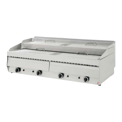
This water grill is made of a stainless steel frame, a cooking grid and radiant elements under which the flames
of main burners heat up the cooking area. Each cooking unit is heated by an atmospheric burner with eight
flames elements controlled by a gas tap. The burners are supplied by a mixture of liquid gas and air or natural
gas and air. Main burner ignition is carried out by a pilot burner. All the main burners are equipped with
safety thermocouples.
Under the cooking units there are drawers to be filled with water when operating the water grill.
Table 1
Model T10 T20 T30
Overall dimensions [mm] 400 x 630 x 430 770 x 630 x 430 1130 x 630 x 430
Main burners (cooking units) 1 2 3
Type of burners Inox Inox Inox
Nominal heat input [kW] .0 18.0 27.0
Installation type A1 according to national installation rules
Gas connection ½ inches male threading complying to standards EN 10226-1 e EN 10226-2
2.2 Technical data plates - Gas categor : II2H3+
Technical Data Unit T10 T20 T30
ormal thermal energy provide Kw 9 18 27
Consumption: G30/G31 28...30/37 mbar Kg/h
0.710 1.420 2.130
Consumption G20…20mbar m³/h
0.95 1.90 2.85
Main air regulation at G30/G31 28...30/37mbar mm 18 18 OPEN
Main air regulation at G20 20mbar mm OPEN OPEN OPEN
Main burner injector G30 28... 30mbar G31 37mbar mm 150 2X150 3X150
Main burner injector G20 20mbar mm 225 2X225 3X225
Bypass G30 28... 30mbar G31 37mbar mm 120 2X120 3X120
Bypass G20 20mbar mm Reg. 2x Reg. 3x Reg.
Calories Kcal 7740 15480 23220
Mj 32.4 4.8 97.2
BTU 30708 141 92124
On the back of appliance there is a technical plate (Fig. 1) and gas setting plate (Fig. 2) reporting
the current gas setting, nominal data of grill and a table with gases, categories and pressures for all
the other EC countries. There is also a warning plate expressed in the language of the country of
destination (Fig. 3).
A third plate with warning and current setting is placed in the appliance packaging (Fig. 3).
Fig. 1_Technical data plate Fig. 2_Gas setting plate
CZ-ES-GR-IE
IT-PT-GB-CH
SK-TR
G30/G31
G20
3+
2H
28-30/37
20
( )
( )
Fig. 3_Warning plate

5
3. INSTALLATION (only for the installer)
3.1 Installation in premises
The installation and the first starting on must be done by qualified personnel, authorised by the manufacturer.
Appliances must be installed in accordance with the national safety standards regarding gas heated appliances.
This gas heated water grill must be installed in a well-ventilated place having permanent ventilation ducts to
guarantee a sufficient exchange of comburent air and to keep the work premise healthy. It is recomended to
install it under an efficient hood that could evacuate burned gases and cooking steams outside of the premise.
The majority of catering kitchens use mechanical ventilation systems to create a comfortable working
environment that promotes health and safety at work and encourages good practice for hygiene and food
safety. These systems are designed to remove the products from the cooking processes and discharge them to
a safe external location, normally through an hood installed over the cooking appliances. Make-up air is
supplied in the form of natural ventilation through air vents, louvres or serving hatches ets. It is important to
recognise that ventilation systems serve several purpose apart from the removal of combustion products.
They:
• Introduce sufficient clean, cool air and remove excess hot air from the cooking area to enable the
occupants to breathe adequately and provide comfortable conditions;
• Prevent incomplete combustion of gas and the consequent production of harmful carbon monoxide;
• Dilute and remove odours, vapours and steam from the cooking process.
According to national Regulations, this gas heated water grill can be installed as an appliance of construction
type:
• For type A appliances, the instructions shall state that these appliances are to be installed with sufficient
ventilation to prevent the occurrence of unacceptable concentrations of substances harmful to health in
the room in which they are installed. Once the equipment has been converted to another type of gas or a
pressure other than those to which it was previously adjusted, the indications of the new adjustment shall
be given instead of the previous indications so as to provide clear identification of the state of the
appliance after modification. Install the appliances only in a suitable ventilated room;
The flow of air required for combustion , install the appliance in a suitably ventilated room in accordance with
the regulation in force
.
3.2 Packing
Make sure packing is intact before remove the appliance. Open cardboard carefully to ensure no metal
stapling, adhesive tape or other packing components litter the environment, as these can prove hazardous.
Remove the protective film from the external walls of the appliance making sure no glue or plastic is stuck on
the surface. If there are residues of glue, remove them using the right solvent.
Make sure the appliance contains all the accessories (cooking grids, handles, etc.).
Check the packaging is marked with the gas available in place.
After removing the packaging, sell off the packing plastics according to laws about recycling. At the end of its
operating life, do not disperse the appliance in open environment but destine it to suitable areas for salvage
materials.
B
A
Fig. 3B_Positioning distances
A ≥ 20 mm
B
≥ 20
m
m

6
3.3 Positioning
Make sure there is enough space available to place the appliance and that the surface it stands on is stable and
level.
Make sure the appliance is level on the surface available. If necessary, regulate its height accordingly, by
adjusting the legs of the appliance.
Make sure that the volume of air required for combustion isn't obstructed in any way by objects around or
under the appliance and no flammable bottle is placed near it.
It is recommended always keeping a distance of at least 20 cm from the two side walls and rear wall and the
appliance especially if the adjacent walls are not protected with refractory sheets or fire-resistant materials
made (see Fig. 3B on previous page).
3.4 Gas connection to the network
Before connecting the appliance to the gas network make sure that:
• The present gas on the place corresponds to that for which the apparatus is predisposed: In If it is not does
not proceed with the connection. Regulate the appliance for the gas available following instructions under
3.6.
• The fixed part of the gas system is conform to the prescriptions established in the Building Regulations in
force in the Country. In particular, verify that the sections of the gas pipes guarantee a supply that is
sufficient for all of the gas heated appliances installed in the same premise avoiding excessive pressure
drops.
• The gas bottle (if present) is placed correctly and protected in a dry area; verify that the visible gas pipes
can easily be inspected; if pipes have been installed in chases (in floors and walls), make sure that this
work has been done to a professional standard with reference points that make it possible to find the
pipeline.
• The flexible hose does not touch hot surfaces, that it isn't put under stress and traction and doesn't come
into contact with sharp edges or other things that could damage it.
• o gas leakage occurs testing along the whole gas circuit and using leak finder sprays or other non-
corrosive foams (do not use direct flames to look for leaks).
• The burners are manufactured with a way to stand thermal and mechanical stress and are equipped with
fixed nozzles. This is why it is necessary to change the nozzles every time you change the type of gas.
• Data concerning the appliance setting are to be found on the label on the backside of the appliance.
• Connect the machine to the network using metal pipes, either rigid or flexible.
• Verify that the pressure in use is that of exercise for which the appliance has been predisposed. In no case
the inlet supplying pressure must exceed the maximal pressure foreseen by gas setting and category
according to the Country of destination (see table 4 at last page).
• Use the right sealing materials for all connections and check them for leaks.
• It is important for the adjacent walls to the appliance to be protected against the heat. Interpose refractory
sheets or place the appliance at least 20 cm of distance from the side or back walls.
• The connection of the apparatus to the gas network must be effected through a gate valve. This
valve should be closed when the appliance is not in operation.
3.5 Gas pressure and nominal heat input controls
The main inlet pressure is measured, being the appliance on, using a pressure gauge for liquids (for example a
manometer with a minimum resolution of 0,1 mbar). Please proceed as follow:
• Open the frontal panel in way to enter to the ramp of feeding of water grill.
• Unscrew the screw-cap of pressure point (pressure point is positioned along the gas ramp between the
external threaded connection and the gas tap).
• Connect the manometer and measure the inlet pressure (with the appliance in operation).
• If the value is not between the min. and max. values indicated in the table 4 (reporting pressures for every
Country, categories and types of gases), the appliance cannot be put into service definitely and the gas
company must be informed in order to find out the problems of supply pressure.
• After this measure, move the manometer, re-screw the screw-cap, and verify that there are not leaks.

7
ominal heat input of appliance can be measured using the gas meter instrument of the premise and a
chronometer; you have to measure the exact gas flow per unit of time, which is consumed when the water
grill (being the only gas heating appliance on) is working at maximum power. This measurement should be
compared to the gas consumption data in technical table A. The tolerance of ± 5 % is allowed for this
measure. If you are measuring top deviations, you should carefully check the diameters and the quality of the
installed nozzles and verify the pressure of the gas network.
3.6 Adaptation to a different gas
If current gas setting of the water grill, which can be verified on labels (either in packaging or in the label
fixed on the back of it), does not correspond to gas available in place the gas adaptation must be carried out.
The appliance should only be adapted by a professionally qualified technician. With reference to technical
data of table 3, replace the main nozzles, the pilot nozzles, adjust correctly the primary air of bush and then
adjust the by-pass screws on gas tapes to set the right rate at the reduced heat input.
Spare nozzles are provided with the appliance on its delivery or can be ordered near the seller.
Make sure that the diameter is printed on each nozzle in 1/100ths of a millimetre. Only adapt the appliance
after you have turned the gas off with the on/off valve upstream and let the appliance cool down.
3.6.1 Replacing the main nozzle and adjusting its primar air
For each main burner, consult technical data on table 3, see Fig. 4 and proceed as follows:
• Access to the main burner after removing the cooking grids, the radiant elements, the drawers
and , in case, overturn the appliance to work easily.
• Unscrew and change the main nozzle “ I “ with the one for the new gas type.
• Adjust correctly the distance H of primary air bush “ B “ according to the new gas setting.
• Fix the air bush by the screw “ V “
• Then replace all the components of the water grill in the reverse order.
I
B
R
V
Z
B = Primary air bush
H = Primary air distance
I = Main nozzle
R = Main burner
V = Fixing screw
Z = as copper pipe Ø 10 mm
Fig 4

8
3.6.2 Replacing the pilot nozzle and adjusting its primar air
For each pilot burner, consult technical data on table 3, see Fig. 5 and proceed as follows
• Access to the pilot burner after removing the cooking grids, the radiant elements, the drawers
and frontal or rear panels.
• Remove the tightening cap “ B “, extract and change the pilot nozzle “ U “ with the one for the
new gas type.
• Adjust correctly the pilot flame primary air by turning the ring nut “ G “ until the flame is stable and
according to pictures (50 % for G20 and G25 gases and 100% for liquid gas G30/G31).
• Then replace all the components in the reverse order.
3.6.3 Adjusting the minimum rate on gas valve through the b -pass screw
The nozzle of the valve by-pass screw has a hole of 1,10 mm Ø and for the gas G30/G31 must be fully
screwed down. Procced in the same way for each burner. For the other gases G20 and G25, the by-pass screw
must be unscrewed for 1 complete round (turning the screw anti-clockwise) until a clear and regular flame
appears. To regulate the by-pass, turn on the burner to the minimum setting, remove the handle grip of the
valve and regulate the by-pass screw marked with “ A “ in the adjacent Figure 6.
BG
P
U
TC
B
=
Tightening cap
=
Sparking plug
G
=
Air ring nut
P
=
Pilot burner
U
=
Pilot nozzle
T
=
Thermocouple
Fig. 5_Pilot nozzle

9
WARNING! After an adaptation to a different gas please remember to:
• Apply an indelible sticker on the technical data plate with the data of the new installation.
• Fix the new seals on the regulated parts (primary air bushes, nozzles and by-pass screws).
• Perform a pressure test of the gas circuit and check for leaks.
• Control the right working of the water grill according to these instructions. Verify the good cross lighting
of main burners, stability and aspect of the flames.
3.7 Interventions, repairs and replacements (onl for authorized technicians)
Even if the appliance is used correctly, some problems may arise for various reasons. The table that follows
mentions some possible problems and some suggestions to put them right.
CAUTION !!!!
• Before performing any intervention of maintenance, reparation or simple cleaning of the appliance it is
necessary to close the gas supply gate valve at the top of the appliance.
• At the end of every intervention of reparation or maintenance to some parts of the appliance relate to gas,
make sure that there are no leaks or losses.
Table 2
PROBLEM POSSIBLE CAUSES
as Smell Possible gas loss.
Check external pipes and connections.
Smell of non-burner gas
Check that the combustion is regular.
Check that the consumption of gas is not excessive.
Check that there are not obstructions in the encircled of the warm smokes.
Check that aspirant and area ventilation are operating property.
‘Explosions ' in the burners Check the pressure of the gas.
The pilot burner does not alight.
Ignition plug is faulty, out of place or its electrical wire is disconnected.
Insufficient gas pressure.
Pilot nozzle is obstructed.
as tap is faulty.
The pilot burner flame does not keep alight. Thermocouple is faulty, it is not well licked up and heated by the pilot
flame.
The main burner is not ignited
Check that there is no leak in the gas supply or any problem with the
nozzle.
Check the components of the burner are well positioned.
Main burners flames are yellow. Primary air bushes are adjusted in a wrong way.
Burner is dirty.
Components replacements:
To replace faulty components it is necessary to remove cooking grids, radiant elements, water
drawers and frontal and back panels. If necessary, we suggest to overturn the grill. Replacing
components, such as the thermocouple, candle of lighting, is simple and intuitive after having
removed the base wall.
• In order to operate on the valve, all it takes is removing the handle grip, and the frontal panel.
• For the substitution of the valve it is necessary to unscrew the connections in the following order:
- First the connection of the thermocouple.
- Then the connection of the gas outlet exit gas.
- Finally; the connection of entrance gas.
Each main burner is equipped with the following safety device:
• Safety thermocouple: in case of pilot flame extinction, the thermocouples cool down and cut off the gas
supply to the main burner. The safety thermocouple is positioned in the pilot group and connected to the
rear part of gas valve (gas tap).

10
4. INSTRUCTIONS FOR USING THE WATER GRILL (for the user)
4.1 Preliminary warnings be ore operating the appliance
• Before operating the appliance, verify it is in efficient condition and it's been installed in an suitable
premise with a well maintained ventilation system capable to keep the work area healthy. Check the
electrical hood is in perfect working order and make sure that the volume of air required for combustion
isn't obstructed in any way by objects around or under the grill. In case of doubt or persistent breakdown
of the appliance, please contact the nearer technical assistance and don't try to solve the problem on your
own. Final user is only responsible for daily routine maintenance as cleaning. This grill must be used by
qualified and trained personnel since it has been designed for a specific and professional use. All of the
operations regarding installation and extraordinary maintenance must be carried out by qualified
technicians according to Regulations in force in the Country.
• In order to use the grill correctly, observe meticulously everything include these pages as well as ordinary
safety measures.
• Before turning the appliance on remember to:
- Verify that there are not escapes of gas and do not light any burner if you smell gas.
- Contact the technical assistance in case of persistent failure.
- Fill the drawers with water to avoid overheating and keep the food tender during cooking.
- Check the cooking grid and radiant elements are clean to avoid the emission of fire from the oils that
have accumulated during previous cooking.
• Please use this water grill only to cook food. Do not use it for different purposes because any other use is
considered improper and dangerous. Control the grill when operating.
• Check the regular lighting of the main burner and verify the stability of the flames passing from the
maximum to the minimum setting. Blue color of flames is an indication of good combustion.
• Before employing the grill for the first time, clean carefully its surfaces to remove industrials oils.
• Use suitable and professional spatulas and forks to move the food on cooking grids; in case, use
professional gloves.
• At the end of work, remember to close the gas tap upstream.
4.2 Turning the burners on and o
Turning the burners on
• Open the gas supply by the tap installed upstream.
• Light the pilot flame pushing and turning slightly anti-clockwise the knob “ K “ from the off position (•)
to the pilot position ( ) up to the reference mark. Keep the knob pressed and operate the ignition device
“ P “ placed on the right of the gas knob. Keep the knob pressed for a few seconds until the thermocouple
heats and then let the knob go and verify the pilot burner is alight.
• Light the main burner flame turning the knob from the pilot position ( ) to the highest flame position.
Let the knob go and see if the main burner is alight and turned on completely.
• The following nick is that of the reduced flame; you can choose this setting once appliance has reached
the desired temperature. See Fig. 7
Turning the burners off
• Turn the knob from the full or reduced rate position to the pilot position ( ) and see if the water grill
main burner is off.
• Turn the knob from the pilot position to the off position (•) and see if the pilot burner is off.
• At the end of work, remember to check all the burners are off and to close the gas tap upstream.
P
K
Fig. 7_Gas controls

11
4.3 Maintenance and cleaning
The water grill must be kept clean and efficient to assure its performances. In the case of troubles do not
tamper any part of it but call technical assistance; all special maintenance and reparing must be done by
specialised technicians. Check periodically the condition of the gas pipes, fittings and burners. For routine
cleaning proceed as follows and observe the recommendations:
• Before performing any job of maintenance or cleaning is necessary to close the gas supply found at the
top of the appliance and let the grill cool down.
• Clean the steel parts daily with soapy water rinse and dry thoroughly. either use products containing
chlorine (bleach, hydrochloric acid, etc.) nor steel wool, brushes or scrapers that could produce rust. Do
not leave food (as acid food, salt, lemon, etc.) on steel parts as it could ruin them.
• ever wash the appliance with direct, high-pressure jets of water.
• Do not use corrosive substances such as hydrochloric acid when cleaning the supporting table.
Warning! if the lighting and control devices are difficult to use, contact the manufacturer promptly that will
provide the necessary assistance.
• It is consulted to the user to undersign a contract of maintenance with technical personnel that foresees at
least one full check-up annually.
• We specifically recommend regular checking to make sure the ignition source and the flame regulation are
clean.
• The gate valve must be checked at least once a year and, if necessary, restored the protection of specific
oil.
• If such an accurate observance of the contained instructions in this manual are observed, ORTH
appliances will allow perfect use and performances for a long time.
The manufacturer cannot be held responsible for any damage caused to property, human beings or animals
due to misuse of the appliances or non-observance of instructions included in this manual.
Table 4 (Countries categories and pressures)
Countries Category Index Type of gas Nominal
Pressure [mbar]
Minimum
Pressure [mbar]
Maximum
Pressure [mbar]
AT-CH II2H3B/P 2H
3B/P
G20
G30/G31
20
50
17
42.5
25
57.5
AL-BA-BG-DK-EE-FI-HR-LT-LV-MK-
NO-RO-SE-SI-UA II2H3B/P 2H
3B/P
G20
G30/G31
20
28-30
17
25
25
35
CZ-ES-GR-IE-IT-PT-GB-CH-SK-TR II2H3+ 2H
3+
G20
G30/G31
20
28-30/37
17
20/25
25
35/45
DE II2ELL3B/P
2E
2LL
3B/P
G20
G25
G30/G31
20
20
50
17
18
42.5
25
25
57.5
BE-FR II2E+3+ 2E+
3+
G20/G25
G30/G31
20/25
28-30/37
17/20
20/25
25/30
35/45
NL II2L3B/P 2L
3B/P
G25
G30/G31
25
28-30
20
25
30
35
IS-CY-MT-HU I3B/P 3B/P G30/G31 28-30 25 35
LU I3+ 3+ G30/G31 28-30/37 20/25 35/45
LU I2E 2E G20 20 17 25

12
This manual suits for next models
2
Table of contents
Other North Grill manuals
Popular Grill manuals by other brands

Char-Broil
Char-Broil The Big Easy user guide

Backyard
Backyard BY16-101-003-04 operating instructions

Kamado Joe
Kamado Joe KAMADO BIG JOE II owner's manual

Dynasty
Dynasty DBQ-30 Installation and user manual

Weber
Weber Smokey Joe Silver 55035 product manual

Outback
Outback Meteor Stainless Steel 4 Assembly and operating instructions