Northern Airborne Technology 247 User manual

Northern Airborne Technology Ltd.
1925 Kirschner Road
Kelowna, BC, Canada.
V1Y 4N7
Telephone (250) 763-2232
Facsimile (250) 762-3374
Issued on the authority of Northern Airborne Technology Ltd.
Copyright 2005
Installation and Operation Manual
Model 247
Audio Mixing Amplifier
(size the image to allow for optimal viewing).
SM247
ISSUE 2.00


Model 247 Audio Mixing Amplifier
SM247 Installation and Operation Manual
Installation and Operation Manual Page iii
ENG-FORM: 820-0114.DOT
CONFIDENTIAL AND PROPRIETARY TO NORTHERN AIRBORNE TECHNOLOGY LTD.
Table of Contents
Section Title Page
1. Description
1.1 Introduction 1-1
1.2 Product Description 1-1
1.3 Design Features 1-1
1.4 Specifications 1-1
1.4.1 Electrical Specifications 1-1
1.4.2 Physical Specifications 1-2
1.4.3 Environmental Specifications 1-2
1.4.4 Product Approval 1-2
2. Installation
2.1 Introduction 2-1
2.2 Unpacking and Inspection 2-1
2.2.1 Warranty 2-1
2.3 Continued Airworthiness 2-1
2.4 Installation Procedures 2-1
2.4.1 Warnings 2-2
2.4.2 Cautions 2-2
2.4.3 Cabling and Wiring 2-2
2.4.4 Mechanical Installation 2-3
2.4.5 Electrical Installation 2-3
2.4.6 Pin Assignment 2-3
2.4.7 Post Installation Checks 2-4
2.5 Adjustments 2-4
2.6 Accessories Required But Not Supplied 2-5
2.7 Installation Drawings 2-5
3. Operation
3.1 Introduction 3-1
3.2 General Information 3-1

Model 247 Audio Mixing Amplifier
SM247 Installation and Operation Manual
Section 1 Rev: 1.00 Issue 2 Page 1-1
ENG-FORM: 800-0115.DOT
CONFIDENTIAL AND PROPRIETARY TO NORTHERN AIRBORNE TECHNOLOGY LTD.
Section 1 Description
1.1 Introduction
Information in this section consists of product description, design features and specifications for the
Model 247 Audio Mixing Amplifier. The Model 247-001 is also included in this manual – any other
derivative product information shall be contained in the applicable manual supplement, which may be
obtained from Northern Airborne Technology Ltd. as required.
Review all notes, warnings and cautions.
1.2 Product Description
The Model 247 Audio Mixing Amplifier contains three electrically independent audio mixing circuits with
four input channels and one output channel each.
The Model 247 is designed for use as a multipurpose mixing amplifier for mixing Aural Warning, Cockpit
Voice Recorder or virtually any aircraft audio signals. Each input is adjustable to accept 0.25 Vrms
microphone input signals, headphone audio signals from a standard aircraft audio system, or receiver
input signals up to 50 mW. Mic bias for each input channel is user selectable. Access for gain
adjustment and mic bias selection is made by cover removal.
Outputs from the Model 247 are designed to drive any impedance from 8 ohms up to 10K ohms. Output
power is limited by 100 ohm resistors on each output. If additional inputs are needed beyond the four
inputs provided for each mixing circuit, an output from one mixer circuit can be fed to the input of another
mixer thereby increasing the size of the mixer. The Model 247 can also drive headsets for headset
amplifier applications.
The Model 247 gain is established at a maximum of 12 dB with the bias/ground jumpers installed.
However, for input signals which do not require DC BIAS or a 600 ohm input impedance, the bias/ ground
jumper for a given input can be removed which will result in an additional 6 dB gain increase (doubling of
the gain).
1.3 Design Features
The Model 247 standard configuration is designed for driving non-DC biased (ground referenced) loads.
The Model 247-001 includes bi-polar output capacitors for compatibility with DC biased loads such as DC
biased microphone inputs to other equipment.
1.4 Specifications
1.4.1 Electrical Specifications
Power Supply: 28 VDC at 150 mA maximum (each circuit).
Maximum current (3 mixer circuits combined) = 450 mA
Input impedance: 600 Ω(15KΩwith gnd/bias jumper removed)

Model 247 Audio Mixing Amplifier
SM247 Installation and Operation Manual
Section 1 Rev: 1.00 Issue 2 Page 1-2
ENG-FORM: 800-0115.DOT
CONFIDENTIAL AND PROPRIETARY TO NORTHERN AIRBORNE TECHNOLOGY LTD.
Output impedance: 100 Ω
Frequency Response: Flat within +3dB from 300 to 6,000 Hz
Distortion: <1% THD+N from 300 to 6,000 Hz
Gain Range: >12 dB
Output: 4.5 Vrms (33mW) into 600 Ω, Outputs are current limited
Note: Model 247-001 includes bi-polar output capacitors for
compatibility with DC biased loads such as microphone inputs
Mic bias 18 Vdc at 30 mA (600 Ωsource impedance) individually selectable
1.4.2 Physical Specifications
Height 41.40 mm (1.63 in) maximum
Depth 76.96 mm (3.03 in) maximum
Width 76.96 mm (3.03 in) maximum excluding flanges
102.36 mm (4.03 in) maximum including flanges
Weight 0.6 kg (0.42 lbs)
Enclosure Conversion coated aluminum
Mounting Bulkhead Mount: four # 8 screws
1.4.3 Environmental Specifications
Temperature -55°to +70°C
Altitude -15,000 to 70,000 feet
Qualification of the Model 247 Audio Mixing Amplifier was completed in accordance with
RTCA/DO-160C Env. Cat. [A2F2]-BA(CL)XXXXXXZ(BZ)AAATZ(XXC2)XX
Note: Refer to Environmental Qualification Form located in Section 2 of this Manual for complete details
of the environmental categories.
1.4.4 Product Approval
FAA: TSO-C50c (RTCA/DO-214 Class Ib, RTCA/DO-160C).
Section 1 ends

Model 247 Audio Mixing Amplifier
SM247 Installation and Operation Manual
Section 2 Rev: 1.00 Issue 2 Page 2-1
ENG-FORM: 805-0118.DOT
CONFIDENTIAL AND PROPRIETARY TO NORTHERN AIRBORNE TECHNOLOGY LTD.
Section 2 Installation
2.1 Introduction
Information in this section consists of unpacking and inspection procedures, installation procedures,
post-installation checks and installation drawings for the Model 247 Audio Mixing Amplifier.
Review all notes, warnings and cautions.
2.2 Unpacking and Inspection
Unpack the equipment carefully and locate the warranty card. Inspect the unit visually for damage due to
shipping and report all such claims immediately to the carrier involved. Check that all items listed below
are present before proceeding and report any shortage immediately to your supplier:
- Warranty Card
- Certificate of Conformity or Release Certification
2.2.1 Warranty
All Northern Airborne Technology Ltd. products are warranted for 2 years from date of installation by an
authorized Northern Airborne Technology Ltd. dealer, to be free of defects in workmanship or
performance. This warranty covers all materials and labour, but is exclusive of any transport to deliver the
defective unit to and from Northern Airborne Technology Ltd. or its designated warranty repair center, or
any labour to remove or re-install the defective unit in the aircraft. Contact Northern Airborne Technology
Ltd. for any questions regarding this warranty, its applicability to your units and/or for return authorization.
Northern Airborne Technology Ltd. is the final arbitrator concerning warranty administration. Units which
have been physically damaged, burned, immersed in water or otherwise abused beyond the scope of
normal use will not be considered for warranty. WARRANTY IS VOID UNLESS THE PRODUCT IS
INSTALLED BY AN AUTHORIZED NORTHERN AIRBORNE TECHNOLOGY LTD. DEALER. Product
for which a warranty card is not returned shall be warranted from date of manufacture.
2.3 Continued Airworthiness
Maintenance of the Model 247 Audio Mixing Amplifier is ‘on condition’ only. Periodic maintenance of this
product is not required.
2.4 Installation Procedures
Installation Notice
This product must be installed in accordance with the installation instructions provided in the latest issue
of this Installation and Operation Manual. Check the NAT Publication Index at www.northernairborne.com
for the issue status of the manual. The latest issue of the manual may be downloaded from the same
website. All risk associated with installation of this product contrary to these instructions shall be the
responsibility of the installing agency.
Model 247 Audio Mixing Amplifier
SM247 Installation and Operation Manual
Section 2 Rev: 1.00 Issue 2 Page 2-2
ENG-FORM: 805-0118.DOT
CONFIDENTIAL AND PROPRIETARY TO NORTHERN AIRBORNE TECHNOLOGY LTD.
2.4.1 Warnings
WARNING:
High volume settings can cause hearing damage.
Set the headset volume control to the minimum volume setting prior to
conducting tests, and slowly increase the headset volume to a
comfortable listening level.
2.4.2 Cautions
CAUTION:
Do not bundle any lines from this unit with transmitter coax feed lines. Do not
bundle any logic, audio, or DC power lines from this unit with 400 Hz synchro
wiring or AC power lines. Do not position this unit next to any device with a
strong alternating magnetic field such as an inverter, motor or blower, or
significant audio interference will result.
In all installations, use shielded cable exactly as shown, and ground only as
indicated. Significant problems may result from not following these guidelines.
Failure to follow the installation and wiring instructions provided in this manual
for power and ground connections, including the rating of the circuit breaker,
may lead to damage in the power input circuitry of the unit.
2.4.3 Cabling and Wiring
All wire shall be selected in accordance with the original aircraft manufacturer's Maintenance Instructions
or AC43.13-1B Change 1, Paragraphs 11-76 through 11-78. Unshielded wire types shall qualify to
MIL-W-22759 as specified in AC43.13-1B Change 1, Paragraphs 11-85, 11-86, and listed in Table 11-11.
For shielded wire applications, use Tefzel MIL-C-27500 shielded wire with solder sleeves (for shield
terminations) to make the most compact and easily terminated interconnect. Follow the Interconnect in
Section 2.7 as required.
Allow 3" from the end of the shielded wiring to the shield termination to allow the connector hood to be
easily installed. Reference the Interconnect drawing in Section 2.7 for shield termination details. Note that
the hood is a "clamshell" hood, and is installed after the wiring is complete.
Maintain wire segregation and route wiring in accordance with the original aircraft manufacturers
Maintenance Instructions.
Unless otherwise noted, all wiring shall be a minimum of 22 AWG, except power and ground lines, which
shall be a minimum of 20 AWG. Reference the Interconnect drawing for additional specifications. Check
that the ground connection is clean and well secured, and that it shares no path with any electrically noisy
aircraft accessories such as blowers, turn and bank instruments or similar loads. Power to this unit must
be supplied from a separate circuit breaker or fuse (fast blow), and not attached to any other circuit
breaker without additional protection. Verify that the selected circuit breaker size and wire gauge are
adequate for the installation using the techniques specified in AC43.13-1B Change 1, Paragraphs 11-47
through 11-51 and 11-66 through 11-69.
Model 247 Audio Mixing Amplifier
SM247 Installation and Operation Manual
Section 2 Rev: 1.00 Issue 2 Page 2-3
ENG-FORM: 805-0118.DOT
CONFIDENTIAL AND PROPRIETARY TO NORTHERN AIRBORNE TECHNOLOGY LTD.
2.4.4 Mechanical Installation
The Model 247 is designed to be mounted in virtually any pressurized or unpressurized location within an
aircraft fuselage. The unit can be mounted in any axis using four (4) #8 mounting screws. No shock or
vibration isolators are required.
The Model 247 must be mounted to a clean metal surface which is electrically bonded to the aircraft
ground plane. The unit is finished with a coating which prevents corrosion. This film is electrically
conductive and should not be removed for electrical bonding.
2.4.5 Electrical Installation
The Model 247 has 3 separate power and ground inputs for each of its 3 internal mixer circuits. This is
designed to allow maximum flexibility for the installer if separate power supplies are used. All three
power and ground inputs can also be connected together and supplied from one source. Maximum
current draw for each mixer circuit within the Model 247 is 0.5 Amps assuming maximum output voltage
into a maximum load of 8 ohms.
2.4.6 Pin Assignment
Pin Assignment Pin Assignment
P40-1 Mixer 1, Input 1 HI P40-2 Mixer 1, Input 2 HI
P40-3 Mixer 1, Input 3 HI P40-4 Mixer 1, Input 4 HI
P40-5 Mixer 1, 28 VDC P40-6 Mixer 2, Input 1 HI
P40-7 Mixer 2, Input 2 HI P40-8 Mixer 2, Input 3 HI
P40-9 Mixer 2, Input 4 HI P40-10 Mixer 2, 28 VDC
P40-11 Mixer 3, Input 1 HI P40-12 Mixer 3, Input 2 HI
P40-13 Mixer 3, Input 3 HI P40-14 Mixer 3, Input 4 HI
P40-15 Mixer 3, 28 VDC P40-16 Mixer 1, Input 1 LO
P40-17 Mixer 1, Input 2 LO P40-18 Mixer 1, Input 3 LO
P40-19 Mixer 1, Input 4 LO P40-20 Mixer 1, Power Return
P40-21 Mixer 2, Input 1 LO P40-22 Mixer 2, Input 2 LO
P40-23 Mixer 2, Input 3 LO P40-24 Mixer 2, Input 4 LO
P40-25 Mixer 2, Power Return P40-26 Mixer 3, Input 1 LO
P40-27 Mixer 3, Input 2 LO P40-28 Mixer 3, Input 3 LO
P40-29 Mixer 3, Input 4 LO P40-30 Mixer 3, Power Return
P40-31 Chassis Ground(shield ground) P40-32 Chassis Ground (shield ground)
P40-33 Chassis Ground(shield ground) P40-34 Mixer 1, Output LO
P40-35 Mixer 1, Output HI P40-36 Chassis Ground (shield ground)
P40-37 Chassis Ground(shield ground) P40-38 Chassis Ground (shield ground)
P40-39 Mixer 2, Output LO P40-40 Mixer 2, Output HI
P40-41 Chassis Ground(shield ground) P40-42 Chassis Ground (shield ground)
P40-43 Mixer 3, Output LO P40-44 Mixer 3, Output HI

Model 247 Audio Mixing Amplifier
SM247 Installation and Operation Manual
Section 2 Rev: 1.00 Issue 2 Page 2-4
ENG-FORM: 805-0118.DOT
CONFIDENTIAL AND PROPRIETARY TO NORTHERN AIRBORNE TECHNOLOGY LTD.
2.4.7 Post Installation Checks
2.4.7.1 Voltage/Resistance Checks
Do not attach the Model 247 until the following conditions are met.
Check the following:
a) Check pin <5> <10> <15> for +28 Vdc relative to ground.
b) Check pins <20> <25> and <30> for ground (less than 0.5Ω).
2.4.7.2 Power On Checks
Power up the aircraft’s systems and verify normal operation of all functions of the Model 247.
Upon satisfactory completion of all performance checks, make all required log book entries, electrical
load, weight and balance amendments and other documentation as required by your local regulatory
agency before releasing the aircraft for service.
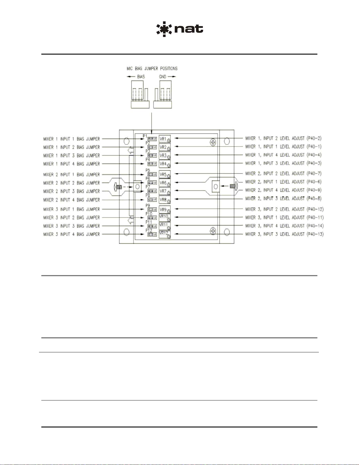
2.5 Adjustments
The Model 247 cover must be removed to gain access to the internal adjustments shown in Figure 1
Internal Adjustments below. Refer to Assembly drawing 247-1 in the SM247 Maintenance manual.
To remove the Model 247 cover, remove the 2 screws in the top of the unit. Do not remove screws under
the base of the unit. Lift the cover to remove.
Reinstall the cover by following the same steps in reverse order. Tighten all screws securely but do not
over-tighten.
CAUTION
The Model 247 Series Audio Mixing Amplifier contains static sensitive
devices. Proper ESD handling procedures must be followed to prevent
damage to the unit.
Model 247 Audio Mixing Amplifier
SM247 Installation and Operation Manual
Section 2 Rev: 1.00 Issue 2 Page 2-5
Figure 1 Internal Adjustments
2.6 Accessories Required But Not Supplied
Installation kit p/n D44SV-IKC (crimp) is required to complete the installation. The kit consists of the
following:
Quantity Description NAT Part No.
1 D-sub Socket, Crimp, Locking 20-21-044
44 Contacts, Crimp, Female 20-26-014
2.7 Installation Drawings
DRAWING REV. DESCRIPTION TYPE SERIAL No.
Model 247
247 1.50 Audio Mixer Amplifier Outline 1000 and up
247\403-0 1.00 Audio Mixer Amplifier Interconnect All
247\247\521-0 1.00 Audio Mixer Amplifier Environmental Qual Form All
Section 2 ends following the above documents
ENG-FORM: 805-0118.DOT
CONFIDENTIAL AND PROPRIETARY TO NORTHERN AIRBORNE TECHNOLOGY LTD.

This page intentionally left blank


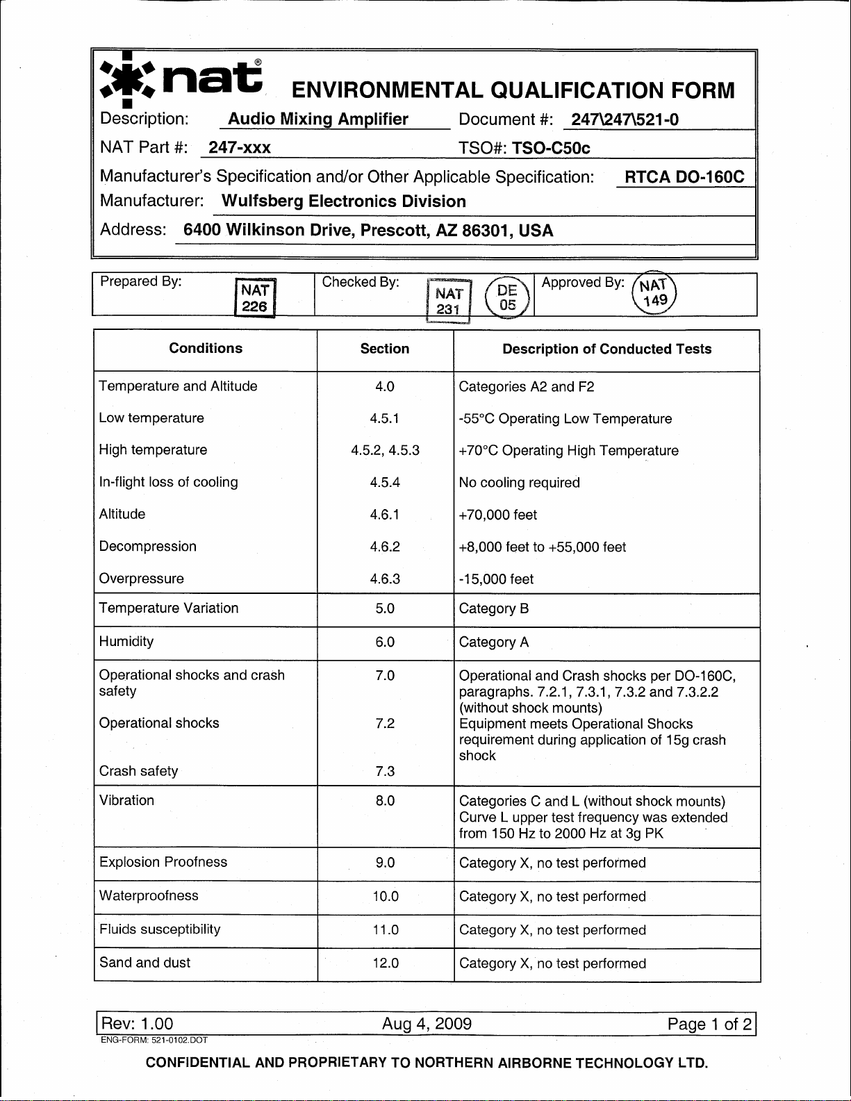

247-xxx Environmental Qualification Form
Rev: 1.00 Aug 4, 2009 Page 2 of 2
ENG-FORM: 521-0102.DOT
CONFIDENTIAL AND PROPRIETARY TO NORTHERN AIRBORNE TECHNOLOGY LTD.
Conditions Section Description of Conducted Tests
Fungus resistance 13.0 Category X, no test performed
Salt spray 14.0 Category X, no test performed
Magnetic effect 15.0 Class Z
Power input 16.0 Categories B and Z
Equipment met requirements for Emergency
Electrical System Operation per DO-160C
subparagraph 16.5.2.1 b (3)
Voltage spike 17.0 Category A
Audio frequency conducted
susceptibility 18.0 Category A
Induced signal susceptibility 19.0 Category A
Radio frequency susceptibility 20.0
Change No. 3 Category T
Emission of radio frequency
energy 21.0 Category Z
Lightning induced transient
susceptibility 22.0
Change No. 2 Category XXC2
Lightning direct effect 23.0 Category X, no test performed
Icing 24.0 Category X, no test performed
REMARKS:
Model 247-xxx was qualified to the environmental test requirements of RTCA DO-160C by similarity to
Model 250-xxx
- Tests of DO-160C, Sections 4.0 (paragraphs 4.5.1, 4.5.2, and.4.5.3), 5.0, 16.0 and 18.0 were
conducted on the Model 250 at dB Systems, Inc. in Redmond, Washington.
- Tests of DO-160C, Sections 4.0 (paragraph 4.6.1), 6.0, 7.0, 8.0, 15.0, 17.0, 19.0, 20.4 (cond. susc.),
21.0, and 22.0 were conducted on the Model 250 at the Eldec Corporation in Lynnwood, Washington.
- Tests of DO-160C, Sections 4.0 (paragraphs 4.6.2, and 4.6.3) and 20.5 (radiated susc.) were
conducted on the Model 250 at Allied Signal in Redmond, Washington.
End of Environmental Qualification Form

Model 247 Audio Mixing Amplifier
SM247 Installation and Operation Manual
Section 3 Rev: 1.00 Issue 2 Page 3-1
ENG-FORM: 806-0114.DOT
CONFIDENTIAL AND PROPRIETARY TO NORTHERN AIRBORNE TECHNOLOGY LTD.
Section 3 Operation
3.1 Introduction
Information in this section consists of the functional and operational procedures for the Model 247 Audio
Mixing Amplifier.
3.2 General Information
The Model 247 Audio Mixing Amplifier has no operator accessible controls. During installation, it may be
determined that internal level adjustments are required. Only qualified personnel shall complete internal
level adjustments.
Section 3 ends
Table of contents
Other Northern Airborne Technology Amplifier manuals


