Northern Airborne Technology PIA01-001 User manual

Northern Airborne Technology Ltd.
1925 Kirschner Road
Kelowna, BC, Canada.
V1Y 4N7
Telephone (250) 763-2232
Facsimile (250) 762-3374
Issued on the authority of Northern Airborne Technology Ltd.
Copyright 2010
Maintenance Manual
PIA01-001
Passenger Intercom Amplifier
SM78
ISSUE 1.00
23-40-95-1
The document reference is online, please check the correspondence between the online documentation and the printed version.

PIA01-001 Passenger Intercom Amplifier
SM78 Maintenance Manual
Maintenance Manual Page ii
ENG-FORM: 823-0106.DOT
CONFIDENTIAL AND PROPRIETARY TO NORTHERN AIRBORNE TECHNOLOGY LTD.
Prepared By: Checked By: Certification: Approved By:
The status of this maintenance manual is controlled by issue shown on the title page. The status of each
section is controlled by revision shown in the footer of each page. All revisions affecting sections of this
manual have been incorporated into the latest issue.
ISSUE/REVISION RECORD
Manual Issue
Number Section
Revision Number Revision Description Issue Date
1.00 Section 4 Rev: 1.00
Section 5 Rev: 1.00
Section 6 Rev: 1.00
Section 7 Rev: 1.00
Initial release Mar 29, 2010
The document reference is online, please check the correspondence between the online documentation and the printed version.

PIA01-001 Passenger Intercom Amplifier
SM78 Maintenance Manual
Maintenance Manual Page iii
ENG-FORM: 823-0106.DOT
CONFIDENTIAL AND PROPRIETARY TO NORTHERN AIRBORNE TECHNOLOGY LTD.
Table of Contents
Section Title Page
4. Theory
4.1 Introduction 4-1
4.2 General Information 4-1
4.3 Theory of Operation 4-1
4.3.1 General 4-1
4.3.2 Power Supply 4-2
4.3.3 Digital Processing 4-2
4.3.4 Analog Processing 4-4
5. Maintenance
5.1 Introduction 5-1
5.2 Continued Airworthiness 5-1
5.3 Disassembly/Reassembly 5-1
5.3.1 Disassembly 5-2
5.3.2 Reassembly 5-2
5.4 Test Equipment 5-2
5.4.1 Test Cables 5-2
6. Documentation and Drawings
6.1 Introduction 6-1
6.2 Documentation and Drawings 6-1
6.2.1 Product 6-1
6.2.2 Product Test and Alignment 6-1
6.3 Subassembly Documentation and Drawings 6-2
6.3.1 Subassembly 6-2
6.4 Software 6-2
7. Bulletins
7.1 Introduction 7-1
7.2 Bulletin Listing 7-1
The document reference is online, please check the correspondence between the online documentation and the printed version.

PIA01-001 Passenger Intercom Amplifier
SM78 Maintenance Manual
Section 4 Rev: 1.00 Issue 1 Page 4-1
ENG-FORM: 842-0114.DOT
CONFIDENTIAL AND PROPRIETARY TO NORTHERN AIRBORNE TECHNOLOGY LTD.
Section 4 Theory
4.1 Introduction
Information in this section consists of general information and theory of operation for the PIA01-001
Passenger Intercom Amplifier.
Refer to Section 6 for supporting documentation and drawings.
Note: This manual does not contain any information on units below MOD 4.
4.2 General Information
The PIA01 is a remote mounted Passenger Intercom Amplifier that supports up to twelve passengers
together on one intercom system (six headset connections on the PIA01, each supporting two headsets
in parallel, if desired). Expansion capabilities are provided through either an analog or digital ICS Tie Line
connection. Only one of these ICS Tie Lines is operational at any given time.
The PIA01 has a number of configurable system parameters providing flexibility for customized
applications. The PIA01 can be configured to support one of three microphone impedances and one of
three headphone impedances. The microphone and headphone impedances selected will apply to all of
the PIA01 users. The headphone outputs will support mono headsets. The microphone audio is
summed together as one group.
The PIA01 is initially intended for application with the Northern Airborne Technology (NAT) Digital Audio
Communication System (DACS). In this configuration, the PIA01 provides intercom audio with the
passengers of the Audio Management Unit (AMU) within the DACS system via the digital ICS Tie Line.
The PIA01 communicates with the AMU using a serial data port. All intercom audio between the PIA01
and AMU is digitized and passed over the serial data port. When used with the DACS, the PIA01 system
parameters are configured using a Personal Computer (PC) connected to the AMU via a Universal Serial
Bus (USB) serial port and NAT supplied DACS Device Configuration software. The PIA01 intercom audio
level and VOX level matches the corresponding levels heard by the passengers connected to the AMU.
The PIA01 can also be used as a stand-alone Passenger Intercom Amplifier. In this configuration, the
PIA01 enables the analog ICS Tie Line for intercom communication with external devices. Microphone
and headphone impedances are selected via discrete inputs on the PIA01external connector. Intercom
audio and VOX levels are adjusted via discrete inputs on the PIA01 external connector.
The PIA01 also features a stereo music input. The stereo signal is summed to a mono signal and routed
to all headphone outputs. The music input level is configurable to support portable or automotive input
levels via discrete inputs on the PIA01 external connector.
4.3 Theory of Operation
4.3.1 General Information
All circuitry is located on the PIA01-1 Main Subassembly. For the sections that follow, refer to the
PIA01-001 Block Diagram (302-0).
The document reference is online, please check the correspondence between the online documentation and the printed version.

PIA01-001 Passenger Intercom Amplifier
SM78 Maintenance Manual
Section 4 Rev: 1.00 Issue 1 Page 4-2
ENG-FORM: 842-0114.DOT
CONFIDENTIAL AND PROPRIETARY TO NORTHERN AIRBORNE TECHNOLOGY LTD.
4.3.2 Power Supply
4.3.2.1 Pre-regulator
The +28 VDC POWER input is overcurrent protected and transient voltage protected, then EMI/RF
filtered and reverse voltage protected. The power input signal is then filtered for audio frequencies before
supplying the +V power supply. This voltage is approximately +26 Vdc. The +V power is a pre-regulated
power supply that feeds one linear regulator and three switch mode regulators.
4.3.2.2 Switching and Linear Regulators
The +V power feeds a linear regulator which feeds two more linear regulators that supply MIC BIAS A
and MIC BIAS B to the microphone input circuits. This voltage is approximately 11.4 Vdc.
The +V power feeds three switch mode power supplies consisting of a positive supply of approximately
+6.5 Vdc, a negative supply of approximately -6.5 Vdc and another positive supply of approximately +5.5
Vdc. These switch mode regulators are synchronized 120 degrees out of phase from each other. The
oscillator frequency is modulated by a spread spectrum frequency modulation scheme to spread the
oscillator’s energy over the range of 275 kHz to 303 kHz.
The +6.5 Vdc switch mode regulator creates a +B supply that feeds the positive rail of the headphone
amplifiers and an +A supply that feeds a linear regulator to create the +5VA power supply.
The -6.5 Vdc switch mode regulator creates a -B supply that feeds the negative rail of the headphone
amplifiers and an -A supply that feeds a linear regulator to create the -5VA power supply.
The +5.5 Vdc switch mode regulator feeds a linear regulator to create the +5VD power supply and
another linear regulator to create the +3.3V power supply. This +3.3V supply feeds another linear
regulator to create the +1.2V power supply.
All three switch mode regulators have an LED to signal status of the respective power supply. When the
LED is illuminated it signifies that the power supply output is operational.
4.3.3 Digital Processing
Audio processing is performed in the digital domain by the Digital Signal Processor (DSP). In support of
the DSP there are coder/decoder’s (CODECs) with 8 inputs and 7 outputs to perform audio conversion
from analog to digital and digital back to analog domain. Flash memory is included to store both
executable code and limited data. A reference oscillator and clock generator are provided to clock the
DSP. Switch buffers are provided to support external discrete and ICS Key inputs as well as the S/PDIF
interface.
The individual function blocks of the Digital Processing section are described in greater detail below:
4.3.3.1 Digital Signal Processor
The DSP performs all of the PIA01 audio processing functions. These functions include audio mixing,
routing, level control, VOX, muting and filtering. The audio processing is performed in the digital domain.
The document reference is online, please check the correspondence between the online documentation and the printed version.

PIA01-001 Passenger Intercom Amplifier
SM78 Maintenance Manual
Section 4 Rev: 1.00 Issue 1 Page 4-3
ENG-FORM: 842-0114.DOT
CONFIDENTIAL AND PROPRIETARY TO NORTHERN AIRBORNE TECHNOLOGY LTD.
The DSP includes a parallel interface that serves as both address and data buss. This interface
communicates with the flash memory and the switch buffers for the external discrete and ICS Key inputs.
A Serial Peripheral Interface (SPI) handles communication to peripheral devices such as the CODECs
and Programmable Gain Amplifiers (PGAs). A serial digital data interface provides the communication link
for the digital ICS tie line.
Support functions of the DSP include: oscillator input, reset input, watchdog timer output and an emulator
port.
4.3.3.2 Flash Memory
The Flash Memory holds the executable program for the DSP. On power up, the Flash Memory contents
are automatically up-loaded into the DSP’s RAM memory and executed. The Flash Memory is read onto
the DSP’s 8 bit data buss which is multiplexed with the address buss A23-8. Two latches hold the
addresses stable while the data is retrieved from the Flash Memory. The upper three bits of the address
lines are used to decode the chip select for the Flash access.
4.3.3.3 Oscillator
The Oscillator circuit provides a 24.576 MHz output signal to the Clock Generator circuit.
4.3.3.4 Reset and Watchdog Timer Circuit
The Reset Circuit monitors the +3.3 Vdc power supply output. When the power supply falls below a pre-
defined threshold, the reset circuit will initiate a reset pulse for the DSP, CODECs and Flash Memory. The
Reset Circuit monitors the DSP watchdog and generates a time-out reset upon time out.
4.3.3.5 Clock Generator
The Clock Generator circuit provides two clock outputs, a 12.288 MHz clock for the DSP and an 8.192
MHz clock for the CODECs. The CODEC clock signal is routed through a second Clock Generator circuit
for buffering purposes.
4.3.3.6 Switch Detection Buffer
The switch detection buffer multiplexes the external ICS key and discrete inputs onto the DSP’s data buss
when activated by the DSP’s address decoder logic and read lines. The ICS key information is used by
the DSP to un-mute microphone audio. The discrete input information is used by the DSP to configure the
PIA01 Microphone Impedance, Phone Impedance, Music Input Level, NAT ICS Tie Line Level, ICS
Volume and VOX threshold Level when the Digital ICS Tie Line connection is absent. When the Digital
ICS Tie Line connection is present, this discrete input information is ignored.
4.3.3.7 RX S/PDIF Buffer
The RX S/PDIF buffer is a receiver circuit that converts the differential low voltage serial data signals from
the external connector into a single ended signal for delivery to the DSP.
The document reference is online, please check the correspondence between the online documentation and the printed version.

PIA01-001 Passenger Intercom Amplifier
SM78 Maintenance Manual
Section 4 Rev: 1.00 Issue 1 Page 4-4
ENG-FORM: 842-0114.DOT
CONFIDENTIAL AND PROPRIETARY TO NORTHERN AIRBORNE TECHNOLOGY LTD.
4.3.3.8 TX S/PDIF Buffer
The TX S/PDIF buffer is a transmitter circuit that converts the single ended data signal from the DSP to a
differential low voltage signal. The differential signal is then coupled through an isolation transformer to
the external connector.
4.3.3.9 CODEC
The CODEC circuit performs analog-to-digital conversion and digital-to-analog conversion. Analog audio
signals are fed into the codec and converted to digital format signals. The digital format audio data is then
fed to the DSP via a serial data communication port. The processed digital signals from the DSP are
routed back to the CODEC through the same serial data communication port. The CODEC then converts
the digital format audio signals received into an analog format. The analog audio signals are then routed
to amplifiers for analog signal conditioning. All of the CODECs are driven by a common clock signal that
is generated by the Oscillator circuit.
4.3.4 Analog Processing
4.3.4.1 Mic Impedance Select
Mic Impedance select is performed for each of the six microphone inputs. The impedance select circuit
consists of four solid state relays. Two solid state relays are used for the 150 Ohm mic select and one
each for the 75 and 5 Ohm mics. When enabled, the solid state relays switch in the proper input
impedance. For the 150 Ohm mic, the solid state relay also provides a mic bias voltage.
4.3.4.2 Programmable Gain Amplifiers
The Programmable Gain Amplifiers (PGAs) provide gain or attenuation for the microphones and receiver
inputs before being digitized by the CODECs. The input signals are adjusted to match the required input
level of the CODECs. The gain control data is provided via a daisy-chained SPI buss from the DSP.
4.3.4.3 Analog ICS Tie Line Amplifiers
There are two Analog ICS Tie Line Amplifiers; the first amplifier drives the external NAT ICS Tie line with
a CODEC output signal. The second ICS Tie amplifier monitors the NAT ICS Tie line and routes the
signal to the input of a CODEC. These two amplifiers provide a bidirectional ICS Tie Line link to the
external connector.
4.3.4.4 Music Amplifier
There is one Music Amplifier that routes the music signal to the input of a CODEC. The music input level
select circuit consists of a solid state relay.
4.3.4.5 Phones Amplifiers
There is a phones amplifier for each of the six phones outputs. The phones amplifier is a high current and
high voltage amplifier. There are built in over-current and over-temperature protection circuits on each
phones amplifier.
The document reference is online, please check the correspondence between the online documentation and the printed version.

PIA01-001 Passenger Intercom Amplifier
SM78 Maintenance Manual
Section 4 Rev: 1.00 Issue 1 Page 4-5
ENG-FORM: 842-0114.DOT
CONFIDENTIAL AND PROPRIETARY TO NORTHERN AIRBORNE TECHNOLOGY LTD.
4.3.4.6 Phones Transformer
There are six phones output transformers which couple phones audio to their respective outputs on the
external connector. Each transformer has one primary winding and three secondary windings. The
primary winding of the transformer is driven by the output of the phones amplifier. The secondary winding
supports a configurable connection to head phones with impedances of 8, 150 or 600 Ohms. The
secondary windings of the transformer are routed to the Impedance Select circuit.
4.3.4.7 Phones Impedance Select
Impedance select is performed for each phones output transformer. The impedance select circuit consists
of three solid state relays. Each solid state relay is connected to one secondary winding on the phones
transformer. When enabled, the solid state relay for each secondary winding allows audio to pass from
the respective secondary transformer winding to the phones output on the external connector. On each
phones output transformer, only one secondary is selected at one time by the Impedance Select circuit.
Section 4 ends
The document reference is online, please check the correspondence between the online documentation and the printed version.

PIA01-001 Passenger Intercom Amplifier
SM78 Maintenance Manual
Section 5 Rev: 1.00 Issue 1 Page 5-1
ENG-FORM: 852-0116.DOT
CONFIDENTIAL AND PROPRIETARY TO NORTHERN AIRBORNE TECHNOLOGY LTD.
Section 5 Maintenance
5.1 Introduction
Information in this section consists of troubleshooting, disassembly/reassembly instructions and test
equipment information for the PIA01-001 Passenger Intercom Amplifier.
Review all notes, warnings and cautions.
Note: This manual does not contain any information on units below MOD 4.
This unit contains electrostatic discharge sensitive components. All assembly/disassembly and
maintenance procedures should be performed at a static protected workstation.
CAUTION:
The PIA01 contains embedded software. If any of the components or
subassemblies is replaced, the embedded software must be reloaded with the
correct revision. Contact Customer Service and Repair to determine the
correct revision of software and Programmable Hardware Installation
Procedure for your unit.
5.2 Continued Airworthiness
Maintenance of the PIA01 Passenger Intercom Amplifier is ‘on condition’ only. Periodic maintenance of
this product is not required.
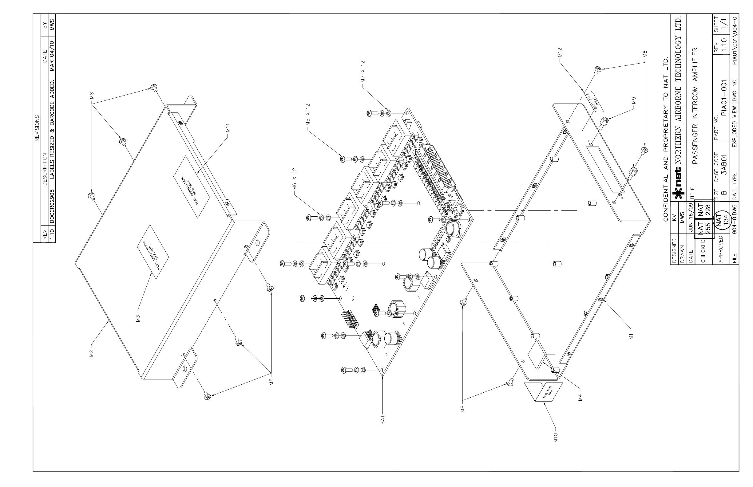
5.3 Disassembly/Reassembly
Refer to Exploded View PIA01\001\904-0 for all disassembly/reassembly procedures. Refer to Section 6
for supporting documentation and drawings.
WARNING:
High volume settings can cause hearing damage.
Set the headset volume control to the minimum setting prior to
conducting tests, and slowly increase the volume to a comfortable
listening level.
CAUTION:
The PIA01 contains surface mount components. Specialized equipment
and training is required to change these components
without causing damage to the unit.
Contact Customer Service & Repair for additional information.
The document reference is online, please check the correspondence between the online documentation and the printed version.

PIA01-001 Passenger Intercom Amplifier
SM78 Maintenance Manual
Section 5 Rev: 1.00 Issue 1 Page 5-2
ENG-FORM: 852-0116.DOT
CONFIDENTIAL AND PROPRIETARY TO NORTHERN AIRBORNE TECHNOLOGY LTD.
CAUTION:
Do not remove components from the product while the unit is turned on. This
could cause damage to the component or unit.
CAUTION:
To prevent movement, some components are secured to the PCB using
adhesive and/or wire. If these components are removed, ensure that they are
re-secured in the same manner when they are replaced to prevent
damage to the unit.
5.3.1 Disassembly
Note: Some screws, shown with an asterisk (*), are secured with Loctite and an initial abrupt twist may
be necessary to break the bond.
5.3.1.1 Remove cover M2 from chassis M1 by unfastening ten screws M8.
5.3.1.2 Release Main Subassembly SA1 from chassis M1 by unfastening J101 jack post set *M9.
5.3.1.3 Release Main Subassembly SA1 from chassis M1 by unfastening 12 screws M5 with 12
lock washers M6 and 12 flat washers M7.
5.3.2 Reassembly
To reassemble the unit reverse the procedures outlined in 5.4.1.
Note: Reapply Loctite 222 to the screws shown with an asterisk (*).
Torque all screws to 5 inch pounds.
5.4 Test Equipment
Refer to Section 6 for supporting documentation and drawings.
5.4.1 Test Cables
The appropriate cables for testing this unit may be fabricated using drawing 08-65-052\953-0. Refer to
Section 6 for supporting documentation and drawings.
Section 5 ends
The document reference is online, please check the correspondence between the online documentation and the printed version.
PIA01-001 Passenger Intercom Amplifier
SM78 Maintenance Manual
Section 6 Rev: 1.00 Issue 1 Page 6-1
ENG-FORM: 862-0117.DOT
CONFIDENTIAL AND PROPRIETARY TO NORTHERN AIRBORNE TECHNOLOGY LTD.
Section 6 Documentation and Drawings
6.1 Introduction
This section contains the documentation necessary for maintenance and troubleshooting of the
PIA01-001 Passenger Intercom Amplifier.
Review all notes, warnings and cautions.
Note: The drawings in this section refer to units MOD 4 and above. For information applicable to items
marked with an asterisk (*) in the MOD column, contact Product Support at Northern Airborne
Technology Ltd.
6.2 Documentation and Drawings
Alternate manufacturers' part numbers may be used. Consult Northern Airborne Technology Ltd. for
approved alternate parts.
6.2.1 Product
DOCUMENT REV. DESCRIPTION TYPE MOD
PIA01-001
PIA01\001\302-0 1.00 Passenger Intercom Amplifier Block Diagram N/A
PIA01\001\521-0 1.00 Passenger Intercom Amplifier Environmental Qual Form 1 - 4
PIA01\001\701-0 1.10 Passenger Intercom Amplifier Parts List 1 - 4
PIA01\001\904-0 1.10 Passenger Intercom Amplifier Exploded View 1 - 4
6.2.2 Product Test and Alignment
WARNING:
High volume settings can cause hearing damage.
Set the headset volume control to the minimum setting prior to
conducting tests, and slowly increase the headset volume to a
comfortable listening level.
For all maintenance procedures, refer to the following documents found at the end of this section.
DOCUMENT REV. DESCRIPTION TYPE MOD
PIA01-001
PIA01\001\518-0 1.00 Passenger Intercom Amplifier Acceptance Test Report 1 - 4
PIA01\001\614-0 1.02Passenger Intercom Amplifier Acceptance Test Procedure 1 - 4
PIA01\001\643-0 1.01 Programmable Hardware Installation Procedure *See 6.1
08-65-052\953-0 1.00 TS-PIA Test Cable Cable Assembly N/A
The document reference is online, please check the correspondence between the online documentation and the printed version.

PIA01-001 Passenger Intercom Amplifier
SM78 Maintenance Manual
Section 6 Rev: 1.00 Issue 1 Page 6-2
ENG-FORM: 862-0117.DOT
CONFIDENTIAL AND PROPRIETARY TO NORTHERN AIRBORNE TECHNOLOGY LTD.
6.3 Subassembly Documentation and Drawings
6.3.1 Subassembly
DOCUMENT REV. DESCRIPTION TYPE MOD
PIA01-1
PIA01-1\401-0 1.20 Main Subassembly Schematic (5 sheets) 1 - 4
PIA01-1\701-0 1.20 Main Subassembly Parts List 1 - 4
PIA01-1\924-0 1.20 Main Subassembly Component Locator (2 sheets) 1 - 4
6.4 Software
SOFTWARE REV. DESCRIPTION CHECKSUM
PIA01-001
702-0121.bin 1.21 Firmware, PIA01-001 0x077DB8AB
This is reference information only. Contact Product Support at Northern Airborne Technology Ltd to obtain
the applicable version.
Section 6 ends following the above documents
The document reference is online, please check the correspondence between the online documentation and the printed version.

The document reference is online, please check the correspondence between the online documentation and the printed version.
ENVIRONMENTAL QUALIFICATION FORM
Description: Passenger Intercom Amplifier Document #: PIA01\001\521-0
NAT Part #: PIA01-001 TSO #: TSO-C139
Manufacturer’s Specification and/or Other Applicable Specification:
RTCA/DO-160E, RTCA/DO-214
Manufacturer: Wulfsberg Electronics Division
Address: 6400 Wilkinson Drive, Prescott, AZ USA 86301
Prepared By: Checked By: Approved By:
Rev: 1.00 Dec 2, 2009 Page 1 of 3
ENG-FORM: 521-0102.DOT
CONFIDENTIAL AND PROPRIETARY TO NORTHERN AIRBORNE TECHNOLOGY LTD.
Conditions Section Description of Conducted Tests
Temperature and Altitude 4.0 Category [(A4)(D1)-]
Ground Survival Low Temperature
Short-Time Operating Low Temp.
Operating Low Temperature
Ground Survival High Temperature
Short-Time Operating High Temp.
Operating High Temperature
In-flight Loss of Cooling
4.5.1
4.5.1
4.5.2
4.5.3
4.5.3
4.5.4
4.5.5
-55° C
-45° C
-40° C
+85° C
+70° C
+70° C
N/A. No forced air cooling.
Altitude
Decompression
Overpressure
4.6.1
4.6.2
4.6.3
+50,000 ft (+15,240 m)
+8,000 ft to +50,000 ft (+2,438 m to + 15,240 m)
-15,000 ft (-4,752 m)
Temperature Variation 5.0 Category B.
Humidity 6.0 Category B.
Operational Shocks and Crash Safety
Operational Shocks
Crash Safety
7.0
7.2.2
7.3.2
7.3.3
Category B.
Alternate Test Procedure.
Alternate Test Procedure (Impulse).
Test Procedure 2 (Sustained), Unknown or
Random orientation in aircraft.
Vibration
8.0
Category [(SBM)(U2FF1)] (without shock
mounts).
The document reference is online, please check the correspondence between the online documentation and the printed version.
PIA01-001 Environmental Qualification Form
Rev: 1.00 Dec 2, 2009 Page 2 of 3
ENG-FORM: 521-0102.DOT
CONFIDENTIAL AND PROPRIETARY TO NORTHERN AIRBORNE TECHNOLOGY LTD.
Conditions Section Description of Conducted Tests
Explosive Atmosphere 9.0 Category X, no test performed.
Waterproofness 10.0 Category X, no test performed.
Fluids Susceptibility 11.0 Category X, no test performed.
Sand and Dust 12.0 Category X, no test performed.
Fungus 13.0 Category X, no test performed.
Salt Fog 14.0 Category X, no test performed.
Magnetic Effect 15.0 Category Z.
Power input
16.0
Category Z.
•The system was tested to DO-160E
subparagraph 16.6.1.3 b, requirement for
equipment with digital circuits.
•The system was tested to DO-160E
subparagraph 16.6.1.1 b (3) Emergency
Operating Voltage conditions.
•The system was tested to DO-160E
subparagraph 16.6.2.2 Low Voltage
Conditions
Voltage Spike
17.0
Category A.
Audio Frequency Susceptibility
18.0
Category Z.
Induced Signal Susceptibility 19.0 Category [ZC].
Radio Frequency Susceptibility
20.0
Category [RR].
Radio Frequency Emission 21.0 Category H.
Lightning Induced Transient
Susceptibility 22.0 Category [A3J33].
Lightning Direct Effects test 23.0 Category X, no test performed.
Icing 24.0 Category X, no test performed.
The document reference is online, please check the correspondence between the online documentation and the printed version.
PIA01-001 Environmental Qualification Form
Rev: 1.00 Dec 2, 2009 Page 3 of 3
ENG-FORM: 521-0102.DOT
CONFIDENTIAL AND PROPRIETARY TO NORTHERN AIRBORNE TECHNOLOGY LTD.
Conditions Section Description of Conducted Tests
Electrostatic Discharge 25.0 Category X, no test performed.
Fire, Flammability 26.0 Category X, no test performed.
Other Tests
REMARKS
•DO-160E, Sections 4 to 8, and 15 to 17 tests were conducted at Northern Airborne Technology
Ltd. (NAT) in Kelowna, BC on PIA01-001.
•DO-160E, Sections 18 to 22 tests were conducted at CKC Laboratories in Bothell, WA on
PIA01-001.
•Testing was performed between Oct 6th and Nov 26th 2009.
End of Environmental Qualification Form
The document reference is online, please check the correspondence between the online documentation and the printed version.

PIA01-001
PIA01\001\701-0
Passenger Intercom Amplifier
Rev:
1.10
NAT Part #:
Document#:
PARTS LIST
Description:
Prepared By: Checked By: Approved By:
Note: Alternate manufacturers' part numbers may be used. Consult NAT for approved alternate parts.
IDENT DESCRIPTION MFR. P/N
OR VALUE PACKAGE NAT P/N QTY.
SUBASSEMBLIES
SA1 Main Subassembly PIA01-1 1
MECHANICAL PARTS
M1 Chassis, PIA01 50-02-089 1
M2 Cover, PIA01 50-03-081 1
M3 Label, Product, PIA01 156-042842-01 43-91-028 1
M4 Gap Filler, Custom, EIS BGA 0.70"x0.70"x0.08" 27-95-081 1
M5 Screw, Panhead, Phillips, Steel MS35206-214 4-40, 0.32" 25-10-214 12
M6 Washer, Locking MS35338-135 #4 25-21-022 12
M7 Washer, Flat .209" OD x 0.115"
ID 25-20-022 12
M8 Screw, Panhead, Phillips, Steel MS35206-212MOD 4-40, 0.165" 25-10-212 10
M9 Jackpost, D-sub, Pair 205817-1 20-27-003 1
M10 Label, Tamper Proof 156-040123-01 43-91-025 1
M11 Label, Decal, ESD Caution 057-03511-0001 43-91-024 1
M12 Label, Bar Code 156-041313-01 43-91-027 1
CONSUMABLES
CS1 Adhesive, Polyurethane, Pink 2041 96-01-001 A/R
CS2 Conformal Coating, Silicone 422 96-00-001 A/R
CS3 Threadlocker, Low Strength 222MS 96-01-010 A/R
End of Parts List
Rev: 1.10
Mar 03, 2010
Page 1 of 1
CONFIDENTIAL AND PROPRIETARY TO NORTHERN AIRBORNE TECHNOLOGY LTD.
Generated by Nat Parts List Manager
ENG-FORM: 701-0123.DOT
The document reference is online, please check the correspondence between the online documentation and the printed version.
The document reference is online, please check the correspondence between the online documentation and the printed version.

ACCEPTANCE TEST REPORT
NAT Part No.: PIA01-001
Description: Passenger Intercom Amplifier
Document No.: PIA01\001\518-0 Rev.: 1.00
Acceptance Test Procedure: PIA01\001\614-0 ATP Rev.: 1.0x
Serial Number: __________
Rev. 1.00 Page 1 of 1
ENG-FORM: 518-0111.DOT Jun 30, 2009
CONFIDENTIAL AND PROPRIETARY TO NORTHERN AIRBORNE TECHNOLOGY LTD.
ATP Results Output
Test Requirement Observation Pass
5. Performance Test
5.1 Supply Current
5.1.2 ≤0.57 Adc
5.1.3 ≤0.89 Adc
5.2 Analog Audio Functions
5.2.1 As per Table 1
5.3 Digital Audio Functions
5.3.8 As per Table 2
5.4 Headset Listening Test
5.4.2 As per Table 3
5.4.3 As per Table 3
5.4.4 As per Table 3
6. Visual Inspection
6.1 No defects or omissions found
Authorized Inspection
Stamp:
Signature: Date:
The document reference is online, please check the correspondence between the online documentation and the printed version.
ACCEPTANCE TEST PROCEDURE
NAT Part No.: PIA01-001
Description: Passenger Intercom Amplifier
Document No.: PIA01\001\614-0 Rev.: 1.02
Prepared By: Checked By: Approved By:
Rev. 1.02 Mar 25, 2010 Page 1 of 11
ENG-FORM: 614-0113.DOT
CONFIDENTIAL AND PROPRIETARY TO NORTHERN AIRBORNE TECHNOLOGY LTD.
1. Product Description
The PIA01 is a remote mounted Passenger Intercom Amplifier that supports up to twelve passengers
together on one intercom system (six headset connections on the PIA01, each supporting two headsets
in parallel, if desired). Expansion capabilities are provided through either an analog or digital ICS Tie Line
connection. Only one of these ICS Tie Lines is operational at any given time.
2. Test Equipment
Model No. Manufacturer Description
ATS-2 Audio Precision Audio Test System with USB-APIB
(USB adapter)
- -
PC with Windows™XP OS with ATS-2
Control Software Rev 1.60 or greater
TS-PIA NAT Test Panel
08-65-052 NAT Test Cable
DM2-2XX Jensen ISO-MAX Isolation Transformer
- - Power Supply, 0-33 Vdc @ 3 A
87* Fluke* Digital Multimeter
H10-76* David Clark Low Z Aviation Headset 5 Ω/8 Ω
H10-36* David Clark High Z Aviation Headset 150 Ω/150 Ω
237040050 S4449-1 Sagem Low Z Aviation Headset 75 Ω/600 Ω
CINJ93-012* Comm Innovations NATO-U92 Headset Adapter
*- an approved equivalent may be substituted.
Reference Prescott document number 150-341897 for acceptable substitute equipment.
3. Pre-connection Checks
3.1 Shake Test
Shake the PIA01 in your hands to make sure there are no loose objects or parts inside the
enclosure.
The document reference is online, please check the correspondence between the online documentation and the printed version.
Table of contents
Other Northern Airborne Technology Amplifier manuals


