Northern Airborne Technology SM251 User manual
Northern Airborne Technology Ltd.
1925 Kirschner Road
Kelowna, BC, Canada.
V1Y 4N7
Telephone (250) 763-2232
Facsimile (250) 762-3374
Issued on the authority of Northern Airborne Technology Ltd.
Copyright 1998
Installation and Operation Manual
Model 251
Passenger Speaker Amplifier
SM251
ISSUE 2.00

Model 251 Passenger Speaker Amplifier
SM251 Installation and Operation Manual
Installation and Operation Manual Page ii
ENG-FORM: 820-0114.DOT
CONFIDENTIAL AND PROPRIETARY TO NORTHERN AIRBORNE TECHNOLOGY LTD.
Prepared By: Checked By: Certification: Approved By:
The status of this installation and operation manual is controlled by issue shown on the title page. The
status of each section is controlled by revision shown in the footer of each page. All revisions affecting
sections of this manual have been incorporated into the latest issue.
ISSUE/REVISION RECORD
Manual Issue
Number Section
Revision Number Revision Description Issue Date
2.00 Section 1 Rev: 1.00
Section 2 Rev: 1.00
Section 3 Rev: 1.00
Rewritten in full NAT format Oct 28, 2009

Model 251 Passenger Speaker Amplifier
SM251 Installation and Operation Manual
Installation and Operation Manual Page iii
ENG-FORM: 820-0114.DOT
CONFIDENTIAL AND PROPRIETARY TO NORTHERN AIRBORNE TECHNOLOGY LTD.
Table of Contents
Section Title Page
1. Description
1.1 Introduction 1-1
1.2 Product Description 1-1
1.3 Design Features 1-1
1.4 Specifications 1-2
1.4.1 Electrical Specifications 1-2
1.4.2 Physical Specifications 1-4
1.4.3 Environmental Specifications 1-4
1.4.4 Product Approval 1-4
1.5 Unit Nomenclature 1-4
2. Installation
2.1 Introduction 2-1
2.2 Unpacking and Inspection 2-1
2.2.1 Warranty 2-1
2.3 Continued Airworthiness 2-1
2.4 Installation Procedures 2-1
2.4.1 Warnings 2-2
2.4.2 Cautions 2-2
2.4.3 Cabling and Wiring 2-2
2.4.4 Mechanical Installation 2-3
2.4.5 Electrical Installation 2-3
2.4.6 Operating Modes 2-4
2.4.7 Wiring Diagram 2-5
2.4.8 Pin Assignment 2-8
2.4.9 Post-Installation Checks 2-9
2.5 Adjustments and Connections 2-10
2.6 Accessories Required But Not Supplied 2-10
2.7 Installation Drawings 2-11
3. Operation
3.1 Introduction 3-1
3.2 General Information 3-1

Model 251 Passenger Speaker Amplifier
SM251 Installation and Operation Manual
Section 1 Rev: 1.00 Issue 2 Page 1-1
ENG-FORM: 800-0115.DOT
CONFIDENTIAL AND PROPRIETARY TO NORTHERN AIRBORNE TECHNOLOGY LTD.
Section 1 Description
1.1 Introduction
Information in this section consists of product description, design features and specifications for the
Model 251 Passenger Speaker Amplifier. All derivative product information shall be contained in the
applicable manual supplement, which may be obtained from Northern Airborne Technology Ltd. as
required.
Review all notes, warnings and cautions.
1.2 Product Description
The Model 251 Passenger Speaker Amplifier is a remotely controlled, electronic unit that operates upon
command from remote switches and potentiometers in the cockpit or cabin of the aircraft.
1.3 Design Features
The Model 251 provides Seat Belt and No Smoking sign chime tones, a Cabin Call ringer tone, ADF, Pilot
Select Comm. (PSC), Briefer, and Cabin Paging audio (all in mono) to the cabin speakers. It also
provides audio from an external AM/FM stereo receiver/cassette tape or CD player (in stereo) to the cabin
speakers and auxiliary monitor outputs.
The left and right speaker amplifier channels are each powered through separate internal fuses so that a
failure in one speaker channel will not disable the other speaker channel or the remaining control circuitry.
The left and right monitor outputs are powered from a third power supply circuit.
A musical chime tone is provided to the cabin speakers to alert the passengers of a change in the Fasten
Seat Belt or No Smoking sign status. A Cabin Call ringer tone is also provided to the cabin for a cockpit
to cabin intercom system. The chime and ringer tones do not pass through either of the electronic
attenuators.
Each left and right speaker amplifier output rating is 28 Watts into 2 ohms (30 Watts typical) or 49 Watts
into 1 ohm. Both speaker amplifier outputs are internally protected against open and short circuits as well
as over-temperature (>105°C).

Model 251 Passenger Speaker Amplifier
SM251 Installation and Operation Manual
Section 1 Rev: 1.00 Issue 2 Page 1-2
ENG-FORM: 800-0115.DOT
CONFIDENTIAL AND PROPRIETARY TO NORTHERN AIRBORNE TECHNOLOGY LTD.
1.4 Specifications
1.4.1 Electrical Specifications
Power Supply: 28 Vdc, 5 ampere maximum.
INPUTS:
ADF: Two individual, switched audio inputs for ADF1 and ADF2.
Input level is 7.75 Vrms.
PSC: One switched audio input compatible with the Pilot Select COMM
output of dB Systems cockpit audio control amplifiers (such as
Models 438 and 700), which provides a 1.00 Vrms signal
produced from a summation of selected COMM, DME and MKR
receivers. The PSC input can also be used for TV audio or other
similar audio.
TV: One switched audio input for TV (or other device). Input level is
1.00 Vrms.
Stereo Left: One switched differential audio input for the left audio channel
from an AM/FM Stereo receiver/tape or CD deck (or other
device). Input level is maximum 0.45 Vrms. (at maximum source
volume) and audio LO is not common to that of other inputs.
Stereo Right: Same as stereo left, switched by the same control input as
stereo left.
Brief: One switched audio input for automated cabin briefer audio.
Input level is 1.00 Vrms.
PA MIC: The microphone input used for cabin paging audio supplies bias
current and is compatible with carbon and amplified dynamic
microphones. Input level is 0.25 Vrms.
Paging Volume: Controls level of PA MIC and brief audio inputs to the PA
sidetone and left and right speaker outputs. Volume control
range is 30 dB (minimum) controlled by a 10,000-ohm, 1/2-Watt,
linear pot. Maximum volume is with maximum resistance.
Receiver Volume: Controls level of ADF, PSC and TV audio inputs to the left and
right speaker outputs. Volume control range is 30 dB (minimum)
controlled by a 10,000-ohm, 1/2-Watt, linear pot. Maximum
volume is with maximum resistance.

Model 251 Passenger Speaker Amplifier
SM251 Installation and Operation Manual
Section 1 Rev: 1.00 Issue 2 Page 1-3
ENG-FORM: 800-0115.DOT
CONFIDENTIAL AND PROPRIETARY TO NORTHERN AIRBORNE TECHNOLOGY LTD.
OUTPUTS:
Right Speaker: The right speaker amplifier is designed for speech and music
signals.
Rated power specification is the maximum power the amplifier
can continuously deliver into the maximum rated load without
clipping.
Rated Power Load
49 W 1 ohm (40 Watts typical)
28 W 2 ohms (30 Watts typical)
15 W 4 ohms (18 Watts typical)
Left Speaker: Same as right speaker specification
Right Monitor: Delivers up to 26 milliwatts into 600 ohms continuously. Factory
calibration is 1.6 mW (1 Vrms).
Left Monitor: Same as right monitor specification
PA Sidetone: 6.7 milliwatts (2 Vrms) into 600 ohms continuous.
Rated and continuous power ratings are the same.
Chime Tone: Generated and supplied to left and right speaker and monitor
outputs when 12 to 32 Vdc is applied to or removed from
connector pins P50-31 or P50-32.
A 790 Hz tone followed by a 610 Hz tone (2-tone, HI/LO) is
factory set for 3.5 VPP (at speaker outputs), adjustable from 1.0
to 6.9 VP-P and is also available at monitor outputs.
Ringer Tone: Generated and supplied to left and right speaker and monitor
outputs when a ground signal is applied to connector pin P50-33.
Ringer tone is 700 ±75 Hz tone, ON for 1.8 ±0.1 second, then OFF
for 3.2 ±0.1second, repeating. Factory set for 1.5 VP-P (700 Hz
component) (at speaker outputs), adjustable from 0 to 5.2 VPP.
Frequency Response: Upper and lower frequency limits are adjustable. Stereo, ADF,
TV, and PSC inputs to speaker and monitor outputs are flat
within 3 dB from 40 Hz to 20,000 Hz. All other inputs to speaker,
monitor, or PA sidetone outputs flat within 3 dB from 300 Hz to
6,000 Hz.
Harmonic Distortion (Thd+N): Less than 0.30 percent distortion, for stereo and less than 1% for
ADF, TV and PSC to all outputs (40 Hz to 20 KHz). Less than
3% for PA and briefer to all outputs (300 Hz to 6 KHz).
Isolation Between Channels: 60 dB, minimum.
Output Noise: Greater than 75 dB below rated, all outputs.

Model 251 Passenger Speaker Amplifier
SM251 Installation and Operation Manual
Section 1 Rev: 1.00 Issue 2 Page 1-4
ENG-FORM: 800-0115.DOT
CONFIDENTIAL AND PROPRIETARY TO NORTHERN AIRBORNE TECHNOLOGY LTD.
1.4.2 Physical Specifications
Height 2.470"
Depth 4.9000" max
Width 7.800" max. including flanges and excluding mating connectors
Weight 2.6 lbs
Mounting Bulkhead Mount (four (4) #8 screws)
1.4.3 Environmental Specifications
Temperature: -55 to +70°C (Operating) Thermal fold-back of the speaker
outputs occurs if the heatsink temperature reaches 105°C.
-55 to +85°C (Survival)
Operating Altitude: 70,000 feet max
Humidity 95% Non-condensing
Shock 15g (any axis)
Vibration RTCA/ DO-160C category CL
Qualification of the Model 251 Passenger Speaker Amplifier was completed in accordance with
RTCA/DO-160C Environmental Categories [A2F2]-BA(CL)XXXXXXZ(BZ)AAATZ(XXC2)XX
Note: Refer to Environmental Qualification Form located in Section 2 of this Manual for
complete details of the environmental categories.
1.4.4 Product Approval
FAA: TSO-C50c (RTCA/DO-214 Class Ib, RTCA/DO-160C)
1.5 Unit Nomenclature
Examples of derivative products are given below. For full information contact Customer Service & Repair.
Model 251-001 Low pass filters adjusted for -3 dB attenuation at 90 Hz on left and right
speaker outputs.
High pass filters adjusted for -3 dB attenuation at 20 Khz on left and right
speaker outputs.
Designed for use with 4-inch speakers.

Model 251 Passenger Speaker Amplifier
SM251 Installation and Operation Manual
Section 1 Rev: 1.00 Issue 2 Page 1-5
ENG-FORM: 800-0115.DOT
CONFIDENTIAL AND PROPRIETARY TO NORTHERN AIRBORNE TECHNOLOGY LTD.
Model 251-002 Identical to 251 Base Model. Part number 251-002 was created to prevent
a conflict with an existing part number 251 in customer part system.
Model 251-003 Identical to 251 Base Model with the following exceptions:
a) Briefing audio is to output through the right speaker only.
b) The receiver inputs and switches are not available.
c) The briefer switch input is externally grounded, disabling the Stereo
Left input and the Stereo Right input.
Section 1 ends

Model 251 Passenger Speaker Amplifier
SM251 Installation and Operation Manual
Section 2 Rev: 1.00 Issue 2 Page 2-1
ENG-FORM: 805-0120.DOT
CONFIDENTIAL AND PROPRIETARY TO NORTHERN AIRBORNE TECHNOLOGY LTD.
Section 2 Installation
2.1 Introduction
Information in this section consists of unpacking and inspection procedures, installation procedures,
post-installation checks and installation drawings for the Model 251 Passenger Speaker Amplifier.
Review all notes, warnings and cautions.
2.2 Unpacking and Inspection
Unpack the equipment carefully and locate the warranty card. Inspect the unit visually for damage due to
shipping and report all such claims immediately to the carrier involved. Check that all items listed below
are present before proceeding and report any shortage immediately to your supplier:
- Warranty Card
- Certificate of Conformity or Release Certification
2.2.1 Warranty
All Northern Airborne Technology Ltd. products are warranted for 2 years from date of installation by an
authorized Northern Airborne Technology Ltd. dealer, to be free of defects in workmanship or
performance. This warranty covers all materials and labour, but is exclusive of any transport to deliver the
defective unit to and from Northern Airborne Technology Ltd. or its designated warranty repair center, or
any labour to remove or re-install the defective unit in the aircraft. Contact Northern Airborne Technology
Ltd. for any questions regarding this warranty, its applicability to your units and/or for return authorization.
Northern Airborne Technology Ltd. is the final arbitrator concerning warranty administration. Units which
have been physically damaged, burned, immersed in water or otherwise abused beyond the scope of
normal use will not be considered for warranty. WARRANTY IS VOID UNLESS THE PRODUCT IS
INSTALLED BY AN AUTHORIZED NORTHERN AIRBORNE TECHNOLOGY LTD. DEALER. Product
for which a warranty card is not returned shall be warranted from date of manufacture.
2.3 Continued Airworthiness
Maintenance of the Model 251 Passenger Speaker Amplifier is ‘on condition’ only. Periodic maintenance
of this product is not required.
2.4 Installation Procedures
Installation Notice
This product must be installed in accordance with the installation instructions provided in the latest issue
of this Installation and Operation Manual. Check the Publication Index at www.northernairborne.com for
the issue status of the manual. The latest issue of the manual may be downloaded from the same
website. All risk associated with installation of this product contrary to these instructions shall be the
responsibility of the installing agency.

Model 251 Passenger Speaker Amplifier
SM251 Installation and Operation Manual
Section 2 Rev: 1.00 Issue 2 Page 2-2
ENG-FORM: 805-0120.DOT
CONFIDENTIAL AND PROPRIETARY TO NORTHERN AIRBORNE TECHNOLOGY LTD.
2.4.1 Warnings
WARNING:
High volume settings can cause hearing damage.
Set the headset volume control to the minimum setting prior to
conducting tests, and slowly increase the headset volume to a
comfortable listening level.
2.4.2 Cautions
CAUTION:
Do not bundle any lines from this unit with transmitter coax feed lines. Do not
bundle any audio or DC power lines from this unit with 400 Hz synchro wiring
or AC power lines. Do not position this unit next to any device with a strong
alternating magnetic field such as an inverter, motor or blower, or significant
audio interference will result.
In all installations, use shielded cable exactly as shown, and ground only as
indicated. Significant problems may result from not following these guidelines.
Failure to follow the installation and wiring instructions provided in this manual
for power and ground connections, including the rating of the circuit breaker,
may lead to damage in the power input circuitry of the unit.
2.4.3 Cabling and Wiring
All wire shall be selected in accordance with the original aircraft manufacturer's Maintenance Instructions
or AC43.13-1B Change 1, Paragraphs 11-76 through 11-78. Unshielded wire types shall qualify to
MIL-W-22759 as specified in AC43.13-1B Change 1, Paragraphs 11-85, 11-86, and listed in Table 11-11.
For shielded wire applications, use Tefzel MIL-C-27500 shielded wire with solder sleeves (for shield
terminations) to make the most compact and easily terminated interconnect. Follow the Wiring Diagram in
Section 2.4.7 as required.
Allow 3" from the end of the shielded wiring to the shield termination to allow the connector hood to be
easily installed. Refer to the Wiring Diagram in Section 2.4.7 for shield termination details. Note that the
hood is a "clamshell" hood, and is installed after the wiring is complete.
Maintain wire segregation and route wiring in accordance with the original aircraft manufacturers
Maintenance Instructions.
Unless otherwise noted, power, ground and speaker wiring shall be a minimum of 20 AWG, and all others
shall be a minimum of 22 AWG. Refer to the Wiring Diagram for additional specifications. Check that the
ground connection is clean and well secured, and that it shares no path with any electrically noisy aircraft
accessories such as blowers, turn and bank instruments or similar loads. Power to this unit must be
supplied from a separate circuit breaker or fuse (fast blow), and not attached to any other circuit breaker
without additional protection. Verify that the selected circuit breaker size and wire gauge are adequate for
the installation using the techniques specified in AC43.13-1B Change 1, Paragraphs 11-47 through 11-51
and 11-66 through 11-69.

Model 251 Passenger Speaker Amplifier
SM251 Installation and Operation Manual
Section 2 Rev: 1.00 Issue 2 Page 2-3
ENG-FORM: 805-0120.DOT
CONFIDENTIAL AND PROPRIETARY TO NORTHERN AIRBORNE TECHNOLOGY LTD.
2.4.4 Mechanical Installation
The Model 251 is designed to be mounted in virtually any pressurized or unpressurized location within an
aircraft fuselage. The unit can be mounted either vertically or horizontally (with the heatsink facing up)
using four (4) #8 mounting screws. The mounting location must provide adequate ventilation to allow heat
dissipation. No shock or vibration isolators are required.
The Model 251 must be mounted to a clean metal surface which is electrically bonded to the aircraft
ground plane. The unit is finished with a coating which prevents corrosion. This film is electrically
conductive and should not be removed for electrical bonding.
2.4.5 Electrical Installation
All inputs and operating modes are electronically switched. Ground signals, supplied by manual switches
in the cockpit, enable the electronic switches in the Model 251. The circuitry is arranged to give audio
priority to paging, briefer, and chimes; the PA MIC, BRIEF, and Seat Belt/No Smoking chime switch
signals mute the Stereo Left, Stereo Right, ADF 1, ADF 2, PSC, and TV audio inputs. PA, briefer, and
chimes will automatically enable speakers even if the speaker switch is off. Microphone bias current is
available from the Model 251 for the PA MIC microphone input.
Electronic attenuators are employed to control paging volume and master receiver (ADF 1, ADF 2, PSC,
and TV) volume. Each attenuator has approximately 30 dB (minimum) of range and is controlled by a
remote volume potentiometer. The potentiometers required are zero to 10,000 ohms, linear taper;
maximum resistance provides maximum volume. The audio source (stereo tape cassette player, etc.) for
the Stereo Left and Right inputs should have its own external volume control attenuator for the Stereo
Input to Speaker and Monitor Output audio channels. The left and right stereo inputs are fully floating
(differential type).
The chime or ringer levels heard in the passenger speakers may be adjusted (see section 2.5).
The control switches shown will switch low current loads and should have a DC rating of 28 Vdc.
The paging and receiver volume control pots required are linear taper, zero to 10,000 ohms, 1/2 watt or
greater. Electrically, the pots are wired to provide maximum resistance to the Model 251 for full volume
(fully clockwise rotation).
Speaker enable inputs are provided to allow remote ON/OFF switching for the left and right speakers.
A remote electronic speaker mute control is also provided. The mute control can be connected to the
aircraft’s Weight-On-Wheels switch to lower speaker volume upon landing when lower cabin ambient
noise levels are present and less speaker volume is needed. The speaker mute control drops speaker
level by approximately 1/2 (-6 dB) when grounded.
Left and right stereo monitor outputs are provided for connecting to a cabin headphone amplifier or
headphone audio distribution system. The monitor outputs are line-level (1 Vrms adjustable) outputs that
carry the same audio signals as the speaker outputs. Unlike the speaker outputs, the monitor outputs
cannot be deselected or muted independently of the normal input switching circuits.

Model 251 Passenger Speaker Amplifier
SM251 Installation and Operation Manual
Section 2 Rev: 1.00 Issue 2 Page 2-4
ENG-FORM: 805-0120.DOT
CONFIDENTIAL AND PROPRIETARY TO NORTHERN AIRBORNE TECHNOLOGY LTD.
2.4.6 Operating Modes
The operating modes of the Model 251 are established when either a ground (low) signal or a 12 to 32
Vdc (high) signal is applied as shown below to the listed connector pin:
Pin No. Control
Signal
Identification
Function
P50-16 Low ADF 1 Switch Connects ADF 1 input audio to left and right speaker and
monitor outputs.
P50-15 Low ADF 2 Switch Connects ADF 2 input audio to left and right speaker and
monitor outputs.
P50-14 Low PSC Switch Connects Pilot Select Comm (PSC) input audio to left and right
speaker and monitor outputs.
P50-13 Low TV Switch Connects TV input audio to left and right speaker and monitor
outputs.
P50-5 Low Stereo Switch Connects stereo left and stereo right input audio to left and
right speaker and monitor outputs, respectively.
P50-24 Low PA Key Connects PA MIC input audio to PA sidetone, left and right
speaker, and monitor outputs. Opens ADF, PSC, TV, and
stereo input audio circuits.
P50-25 Low Briefer Switch Connects briefer input audio to PA sidetone, left and right
speaker, and monitor outputs. Opens ADF, PSC, TV, and
stereo input audio circuits.
P50-31* No Smoking Chime tone to left and right speaker and monitor outputs.
Opens ADF, TV, PSC, and stereo inputs.
P50-32* Seat Belt Chime tone to left and right speaker and monitor outputs.
Opens ADF, TV, PSC, and stereo inputs.
P50-33 Low Cabin Call Ringer tone to left and right speaker and monitor outputs.
P50-34 Low Hook Switch Disables ringer tone.
P60-8 Low Speaker Enable Enables left and right speaker outputs.
P60-3 Low Speaker Mute Mutes (lowers volume -6 dB) left and right speaker outputs.
*An application or removal of a High signal at pins P50-31 and P50-32 will provide a chime tone at left
and right speaker outputs regardless of speaker enable status.
Note: P50-XX is a pin on the 37-pin connector, P50
P40-XX is a pin on the 25-pin connector, P40
P60-XX is a pin on the 9-pin connector, P60
The amplifiers are adjusted for acceptable listening output levels into the proper loads with ADF receiver
inputs of 7.75 Vrms, stereo audio inputs of 0.45 Vrms, PSC, TV, and Briefer audio inputs of 1.00 Vrms
and PA MIC input of 0.25 Vrms. With the volume controls set to maximum volume position, these inputs
will provide 7.5 Vrms (28 watts) into 2 ohms at each speaker output. The ADF receiver input levels are
achieved when receivers are set for 100 milliwatts into 600 ohms. If levels are greatly exceeded at any of
the inputs, the audio will become distorted due to peak clipping, and audio bleed-through will occur.
However, the amplifiers will not be damaged.
Model 251 Passenger Speaker Amplifier
SM251 Installation and Operation Manual
Section 2 Rev: 1.00 Issue 2 Page 2-5
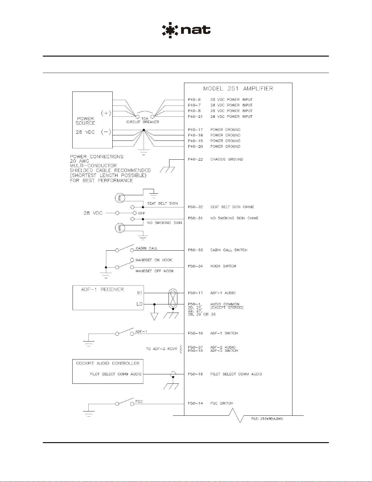
2.4.7 Wiring Diagram
ENG-FORM: 805-0120.DOT
CONFIDENTIAL AND PROPRIETARY TO NORTHERN AIRBORNE TECHNOLOGY LTD.
Model 251 Passenger Speaker Amplifier
SM251 Installation and Operation Manual
Section 2 Rev: 1.00 Issue 2 Page 2-6
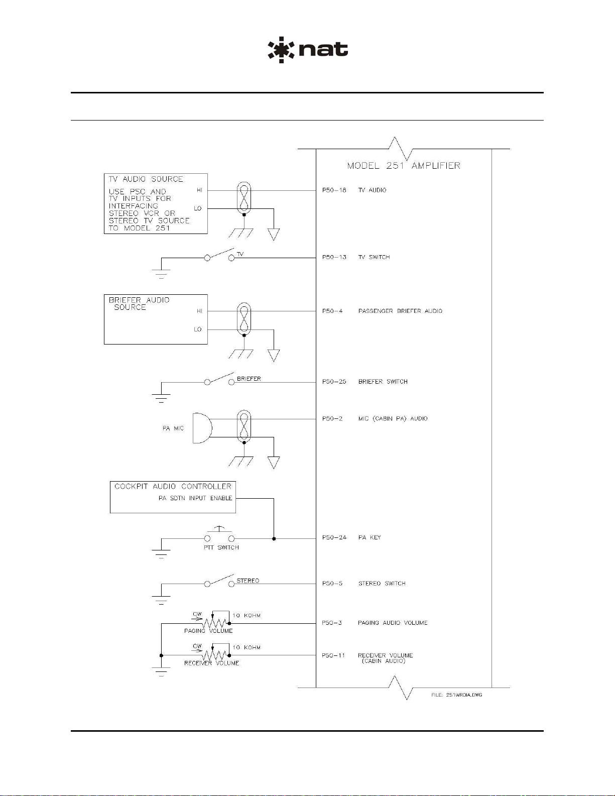
Wiring Diagram (continued)
ENG-FORM: 805-0120.DOT
CONFIDENTIAL AND PROPRIETARY TO NORTHERN AIRBORNE TECHNOLOGY LTD.
Model 251 Passenger Speaker Amplifier
SM251 Installation and Operation Manual
Section 2 Rev: 1.00 Issue 2 Page 2-7
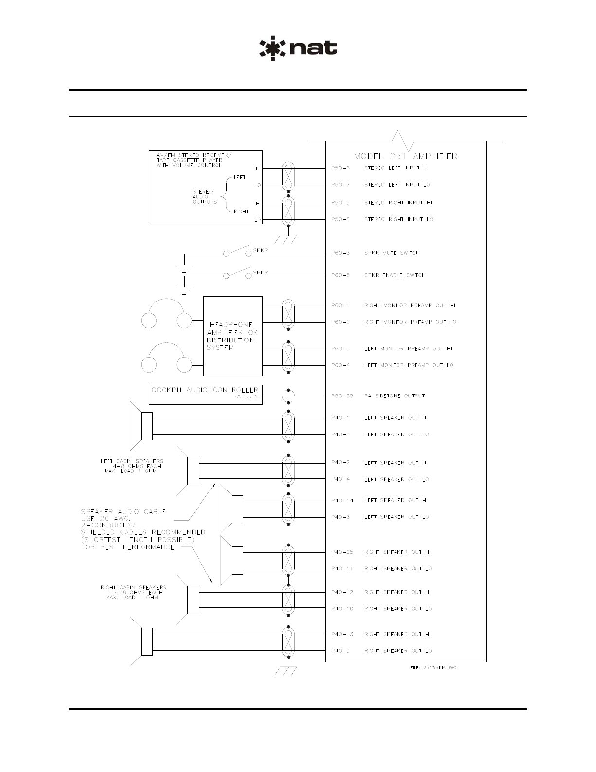
Wiring Diagram (continued)
ENG-FORM: 805-0120.DOT
CONFIDENTIAL AND PROPRIETARY TO NORTHERN AIRBORNE TECHNOLOGY LTD.

Model 251 Passenger Speaker Amplifier
SM251 Installation and Operation Manual
Section 2 Rev: 1.00 Issue 2 Page 2-8
ENG-FORM: 805-0120.DOT
CONFIDENTIAL AND PROPRIETARY TO NORTHERN AIRBORNE TECHNOLOGY LTD.
2.4.8 Pin Assignment
P40 (25-pin connector):
Pin Function Pin Function
1 Left Spkr Out HI 14 Left Spkr Out HI
2 Left Spkr Out HI 15 No connection
3 Left Spkr Out LO 16 No connection
4 Left Spkr Out LO 17 Power Ground
5 Left Spkr Out LO 18 Power Ground
6 28 VDC 19 Power Ground
7 28 VDC 20 Power Ground
8 28 VDC 21 28 VDC
9 Right Spkr Out LO 22 Chassis Ground
10 Right Spkr Out LO 23 No connection
11 Right Spkr Out LO 24 No connection
12 Right Spkr Out HI 25 Right Spkr Out HI
13 Right Spkr Out HI
P50 (37-pin connector):
Pin Function Pin Function
1 Audio Common (except stereo) 20 Audio Common (except stereo)
2 PA MIC HI 21 Audio Common(except stereo)
3 Paging Volume 22 Audio Common(except stereo)
4 Briefer Audio HI 23 No connection
5 Stereo Switch 24 PA Key
6 Left Input HI 25 Briefer Switch
7 Left Input LO 26 No connection
8 Right Input LO 27 Audio Common(except stereo)
9 Right Input HI 28 Audio Common(except stereo)
10 No Connection 29 Audio Common(except stereo)
11 Receiver Volume Control 30 No connection
12 No connection 31 Smoking Sign Switch
13 TV Switch 32 Seat Belt Sign Switch
14 PSC Switch 33 Cabin Call Switch
15 ADF2 Switch 34 Hook Switch
16 ADF1 Switch 35 PA Sidetone HI
17 ADF1 Audio HI 36 Audio Common(except stereo)
18 TV Audio HI 37 ADF2 Audio HI
19 PSC Audio HI
P60 (9-pin connector):
Pin Function Pin Function
1 Right Monitor Output HI 6 No Connection
2 Right Monitor Output LO 7 No Connection
3 Speaker Mute 8 Speaker Enable
4 Left Monitor Output LO 9 No Connection
5 Left Monitor Output HI

Model 251 Passenger Speaker Amplifier
SM251 Installation and Operation Manual
Section 2 Rev: 1.00 Issue 2 Page 2-9
ENG-FORM: 805-0120.DOT
CONFIDENTIAL AND PROPRIETARY TO NORTHERN AIRBORNE TECHNOLOGY LTD.
2.4.9 Post-Installation Checks
2.4.9.1 Voltage/Resistance Checks
Do not attach the Model 251 until the following conditions are met.
Check the following:
a) Check P40 pins <6> <7> <8> and <21> for +28 Vdc relative to ground.
b) Check P40 pins <17> <18> <19> and <20> for power ground (less than 0.5Ω).
c) Check P40 pin <22> for chassis ground (less than 0.5Ω).
c) Check P50 pins <33> <34> <16> <14> <13> <25> and <5>, and P60 pins <3> and <8> for
continuity to ground (less than 0.5Ω) when the relevant switches are closed.
2.4.9.2 Power On Checks
Power up the aircraft’s systems and confirm normal operation of all functions.
Upon satisfactory completion of all performance checks, make all required log book entries, electrical
load, weight and balance amendments and other documentation as required by your local regulatory
agency before releasing the aircraft for service.
Model 251 Passenger Speaker Amplifier
SM251 Installation and Operation Manual
Section 2 Rev: 1.00 Issue 2 Page 2-10
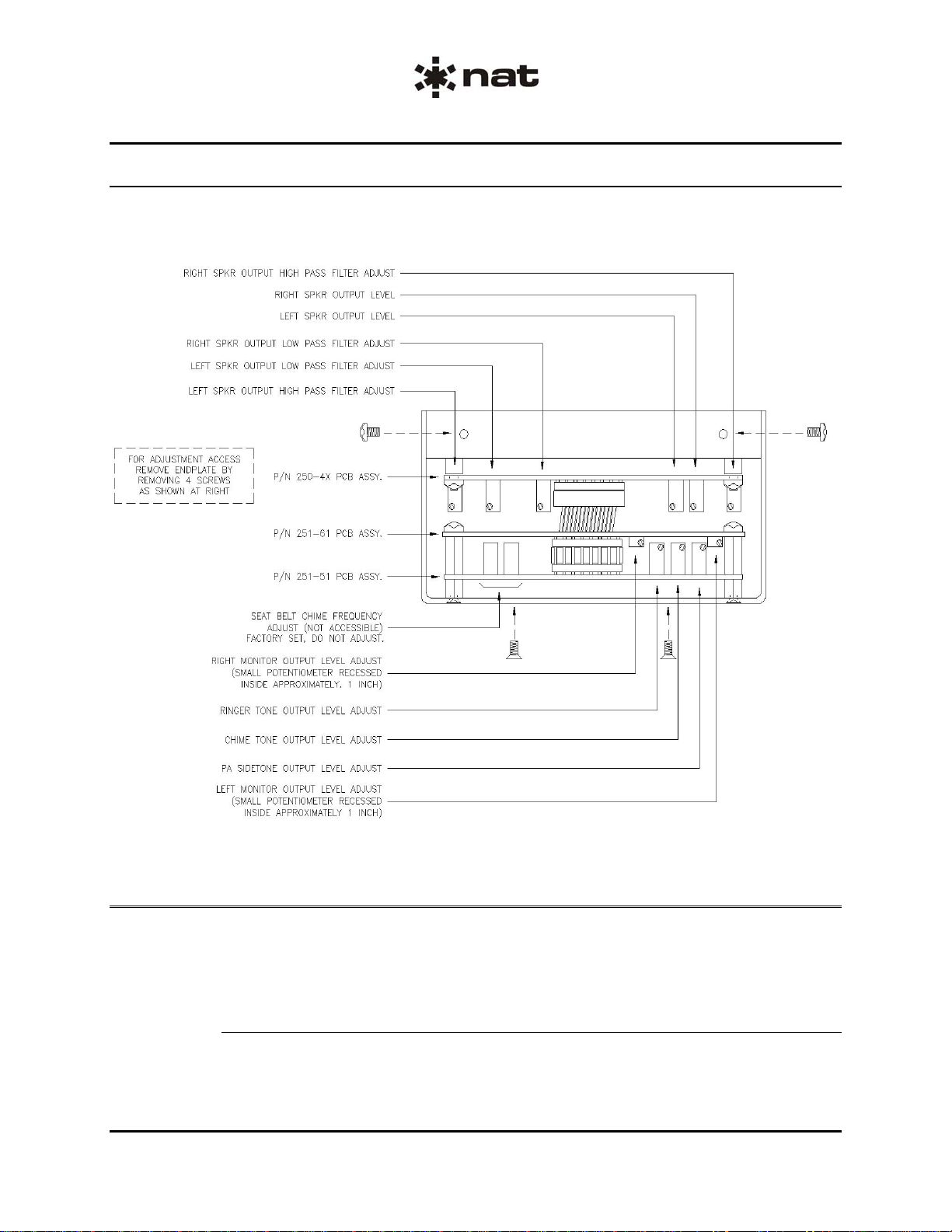
2.5 Adjustments and Connections
Internal screwdriver potentiometer adjustments are accessible, after removal of the Model 251 end plate,
to set various chime or ringer levels heard in the passenger speakers.
Figure 1: Internal Trim Pot Adjustments
2.6 Accessories Required But Not Supplied
Installation kits p/n D09SV-IKC, D25SV-IKC & D37SV-IKC (crimp) are required to complete the
installation. The kits consist of the following:
D09SV-IKC consists of:
Quantity Description NAT Part No.
1 D-min 9 Socket Housing 20-21-009
9 MS Crimp Socket 20-26-901
1 9 Pin JVL Hood/Locklever 20-29-090
ENG-FORM: 805-0120.DOT
CONFIDENTIAL AND PROPRIETARY TO NORTHERN AIRBORNE TECHNOLOGY LTD.

Model 251 Passenger Speaker Amplifier
SM251 Installation and Operation Manual
Section 2 Rev: 1.00 Issue 2 Page 2-11
ENG-FORM: 805-0120.DOT
CONFIDENTIAL AND PROPRIETARY TO NORTHERN AIRBORNE TECHNOLOGY LTD.
D25SV-IKC consists of:
Quantity Description NAT Part No.
1 D-min 25 Socket housing 20-21-025
25 MS Crimp Socket 20-26-901
1 25 pin JVL Hood/Locklever 20-29-250
D37SV-IKC consists of:
Quantity Description NAT Part No.
1 D-min 37 Socket Housing 20-21-037
37 MS Crimp Socket 20-26-901
1 37 Pin JVL Hood/Locklever 20-29-370
2.7 Installation Drawings
DOCUMENT REV. DESCRIPTION TYPE SERIAL No.
Model 251
251\251\521-0 1.00 Passenger Speaker Amplifier Environmental Qual. Form 1000 and up
251 1.52 Passenger Speaker Amplifier Outline 1000 and up
Section 2 ends following the above documents
ENVIRONMENTAL QUALIFICATION FORM
Description: Passenger Speaker Amplifier Document #: 251\251\521-0
NAT Part #: 251-xxx TSO#: TSO-C50c
Manufacturer’s Specification and/or Other Applicable Specification: RTCA DO-160C
Manufacturer: Wulfsberg Electronics Division
Address: 6400 Wilkinson Drive, Prescott, AZ USA 86301
Prepared By: Checked By: Approved By:
Rev: 1.00 Jul 28, 2009 Page 1 of 2
ENG-FORM: 521-0102.DOT
CONFIDENTIAL AND PROPRIETARY TO NORTHERN AIRBORNE TECHNOLOGY LTD.
Conditions Section Description of Conducted Tests
Temperature and Altitude
Low temperature
High temperature
In-flight loss of cooling
Altitude
Decompression
Overpressure
4.0
4.5.1
4.5.2, 4.5.3
4.5.4
4.6.1
4.6.2
4.6.3
Categories A2 and F2
-55°C Operating Low Temperature
+70°C Operating High Temperature
No cooling required
+70,000 feet
+8,000 feet to +55,000 feet
-15,000 feet
Temperature Variation 5.0 Category B
Humidity 6.0 Category A
Operational shocks and crash
safety
Operational shocks
Crash safety
7.0
7.2
7.3
Operational and Crash shocks per DO-160C,
paragraphs. 7.2.1, 7.3.1, 7.3.2 and 7.3.2.2
(without shock mounts)
Equipment meets Operational Shocks
requirement during application of 15g Crash
Shock
Vibration 8.0 Categories C and L (without shock mounts)
Curve L upper test frequency was extended
from 150 Hz to 2000 Hz at 3g PK
Explosion Proofness 9.0 Category X, no test performed
Waterproofness 10.0 Category X, no test performed
Fluids susceptibility 11.0 Category X, no test performed
Sand and dust 12.0 Category X, no test performed
Fungus resistance 13.0 Category X, no test performed
Table of contents
Other Northern Airborne Technology Amplifier manuals


