Northern Lights Everbright Rear Drive SE01 User manual

SE01 INSTRUCTION MANUAL

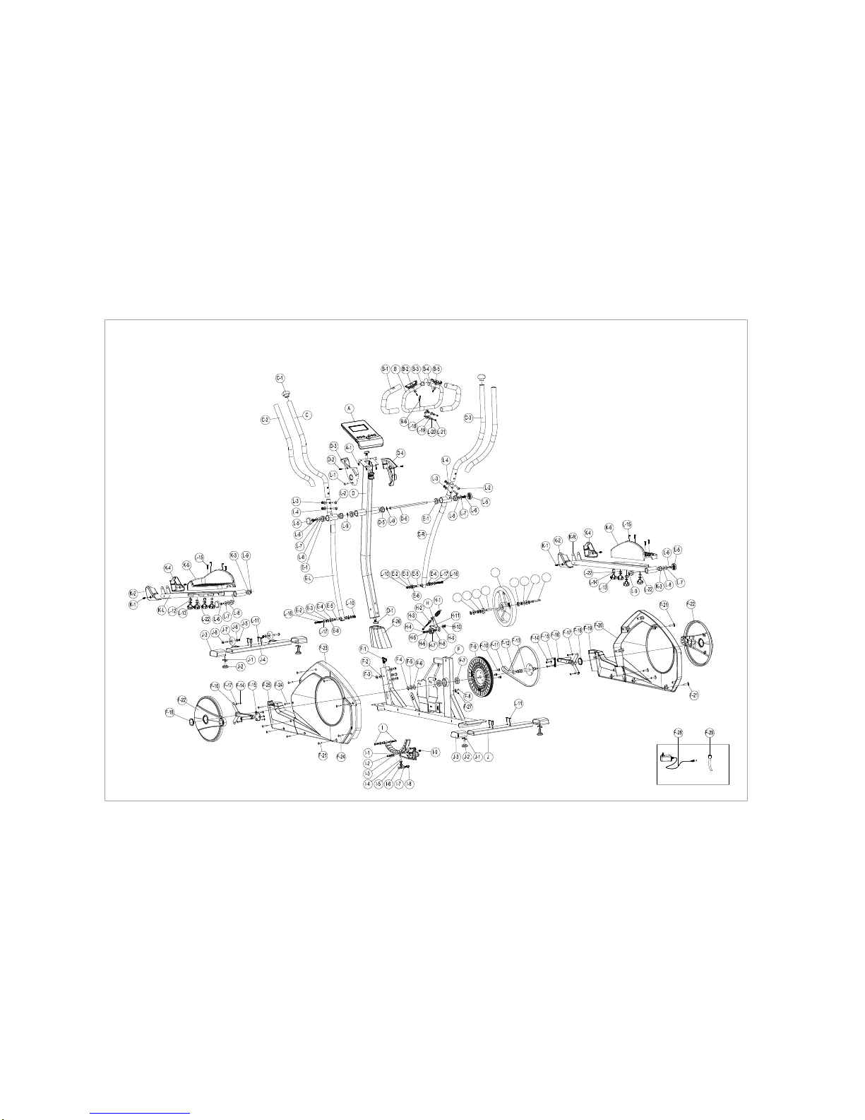
Exploded drawing.
G
G-4
G-3
G-2
G-1
G-5 G-6 G-7 G-8

Parts List
Number
Description
Q'ty
Unit
A, A-1
Console & Screw
1
PCS
B
Front handlebar set
1
PCS
B-1
Foam grip
2
PCS
B-2
Hand pulse
2
PCS
B-3
End cap
2
PCS
B-4
Screw M4x20L
2
PCS
B-5
Semi-circle washer 1.5T
2
PCS
B-6
Wire for hand pulse
1
PCS
C
Upper handlebar (Left)
1
PCS
C-1
End cap
2
PCS
C-2
Foam grip
2
PCS
C-3
Upper handlebar (Right)
1
PCS
D
Handlebar post
1
PCS
D-1
Cable (upper) for console
1
PCS
D-2
Screw M5xP0.8x12L
2
PCS
D-3
Cover for console holder(Left)
1
PCS
D-4
Cover for console holder(right)
1
PCS
D-5
Bushingφ38.1xφ17.12x15L
2
PCS
D-6
Axle for the handlebar
1
PCS
E-L
Lower handlebar(Left)
1
PCS
E-R
Lower handlebar(Right)
1
PCS
E-1
Bushing φ38.1xφ17.12x15L
4
PCS
E-2
C type ringφ12
4
PCS
E-3
Flat washerφ12xφ19x1t
4
PCS
E-4
Bushingφ12xφ16
4
PCS
E-5
Sleeveφ16*φ20*26L
2
PCS
E-6
Wave washerφ12.5xφ18x0.3t
4
PCS
F
Main frame
1
PCS
F-2
Flat washerφ8*φ19*2T
4
PCS
F-3
Allen bolt M8*P1.25*16L(6m/m)
4
4
F-4
C type ringφ20
1
PCS
F-5
Wave washerφ20xφ30x0.3t
1
PCS
F-6
Flat washerφ20.3xφ30x1t
1
PCS
F-7
Bearing
2
PCS
F-8
Sensor box
1
PCS
F-9
Big pulley
1
PCS
F-10
Hex. Screw M8xP1.25x12Lx5t
3
PCS
F-11
Belt
1
PCS
F-12
Sleeveφ20.5xφ25x7.5mm
1
PCS
F-13
Shaft
1
PCS
F-14
Screw M4*12L
5
PCS

F-15
Inside cover for the disc
2
PCS
F-16
Cross disc
2
PCS
F-17
Flat washerφ5xφ16x1t
4
PCS
F-18
Cap for the disc
2
PCS
F-19
Front cover (Right )
1
PCS
F-20
Chain cover(Right )
1
PCS
F-21
Screw M5x16L
8
PCS
F-22
Round disc
2
PCS
F-23
Chain cover(Left)
1
PCS
F-24
Self tapping screw
7
PCS
F-25
Front cover (Left)
1
PCS
F-26
Cover for the handlebar post
1
PCS
F-27
Screw for sensor box
1
PCS
F-28
Adaptor
1
PCS
F-29
DC wire
1
PCS
G~G-8
Flywheel set
1
PCS
H-1~H-11
Idler wheel set
1
SET
I ~I-9, F-1
Magnetic set + Gear box
1
PCS
J
Rear stabilizer
1
PCS
J-1
Block for the adjustable foot cap
4
PCS
J-2
Adjustable foot cap
4
PCS
J-3
Foot cap
4
PCS
J-4
Front stabilizer
1
PCS
J-5
Nylon nut M8
2
PCS
J-6
Flat washerφ8*φ19*2T
2
PCS
J-7
Transportation wheel
2
PCS
J-8
Screw M8xP1.25x40L
2
PCS
K-L
Left pedal arm
1
PCS
K-1
Screw M5xP0.8x12L
4
PCS
K-2
Front cover for Left pedal arm
2
PCS
K-3
Bushingφ26.7xφ17.12x15L
4
PCS
K-4
Front cover for pedal arm(R )
2
PCS
K-5
Left pedal
1
PCS
K-6
Right pedal
1
PCS
K-R
Right pedal arm
1
PCS
L-1~L-22
Bolts & Nuts pack
1
SET

Assembly Stage #1
1. Attach the Front Stabilizer (J-4) to the Main Frame (F) using four Allen bolt (L-11)
2. Attach the Rear Stabilizer (J) to the Main Frame (F) using four Allen bolt (L-11).
.
3. Please remove the handlebar post cover (F-26) from the main frame (F).
After assembly, the Trainer can be adjusted to slightly uneven ground by adjusting the height of
the foot caps at the front and back. The pre-assembled transportation wheels in the front allow
easy moving of the Elliptical and therefore during assembly, need to be pointing down at the front
(45°).
Assembly Stage #2
1. Assemble the pedal arm (K-L, K-R) to the disc by Plastic washer (L-7), flat washer (L-8),
wave washer (L-9) and nylon screw (L-6).
2. Assemble the cap (L-5) for pedal arm (K-L, K-R)
3.
1
2
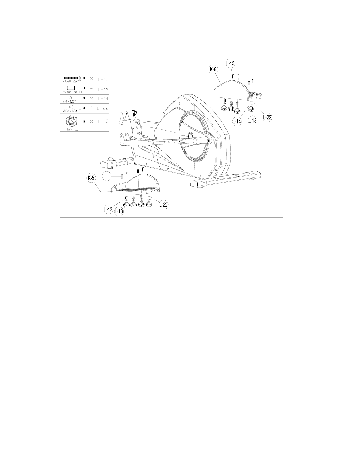
Assembly Stage #3
1. Put pedal(K-5, K-6) onto the pedal arm and tighten it, using 4 knob (L-13), flat washers
(L-22), spring washer (L-14), sleeve (L-12)and bolts(L-15) in each side
Please note that the left and right pedals need to be placed in identical positions.
3
L-15

Assembly Stage #4
1.Please remove four sets of theAllen bolt (F-3) and Flat Washer (F-2)from the Main
Frame (pt.F)
2.Take the Handlebar post (D) and pass it through the Handlebar post cover (F-26).
3. Hold the Handlebar Post (D) and connect the Lower Computer Cable (F-1) and the
Upper Computer Cable (pt. D-1)
4.Slide the Handlebar Post (D) into the Main Frame then fix with four sets of Allen bolt
(pt.F-3) and Flat Washers (pt.F-2).
4
12* 19*1T M8*16L
4* 1*

Assembly Stage #5
1. Disassemble one side of the pre-assembled screw (L-6) on axle, insert the axle into the whole
movable handlebars and handlebar post . Then tighten the end using one plastic washer (L-7),
flat washer (L-8), wave washer (L-9) and screw (L-6) in each side.
2. Tight the carriage bolts (L-16) with flat washer (L-17) and nylon nut (L-10) to connect the pedal
arm (K-L/R) and lower handlebar (E-L/R) in each side.
Assembly Stage #6
.
1. Please remove four sets of the screw (K-1) from the pedal arm (K-2, K-4).
2. Assemble the front cover for the pedal arm (K-2, K-4) by screw (K-1) in each side.
5
6
M5*12L
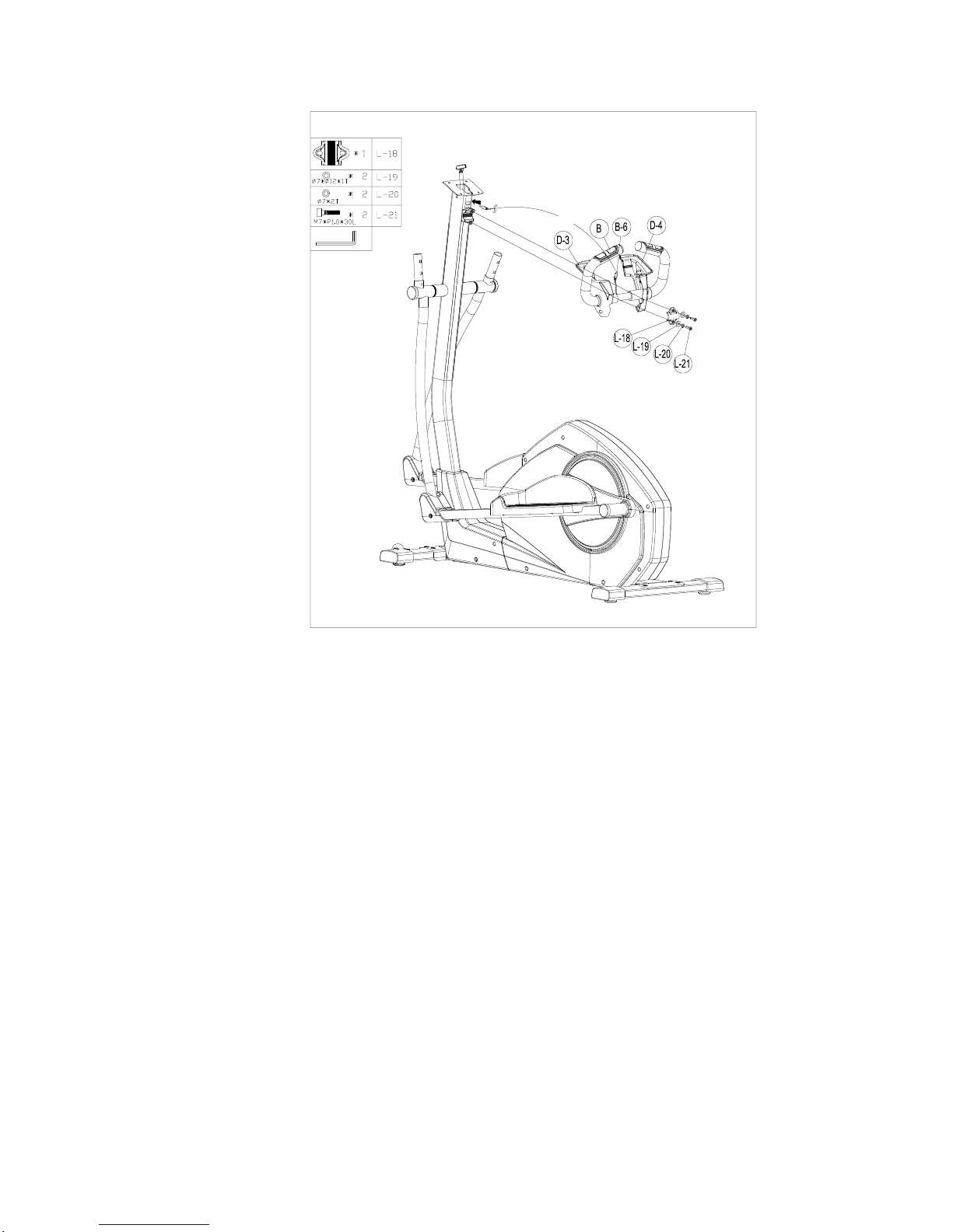
Assembly Stage #7
1. Pass the hand-pulse wire (pt.B-6) through the handlebar post hole.
2. Attach the Front handlebar (B) to the Handlebar post (D) using the clamp cover (L-18),
and then fix with two Flat Washers (L-19), two Spring Washers (L-20), two Fixing Bolt
(L-21).
7
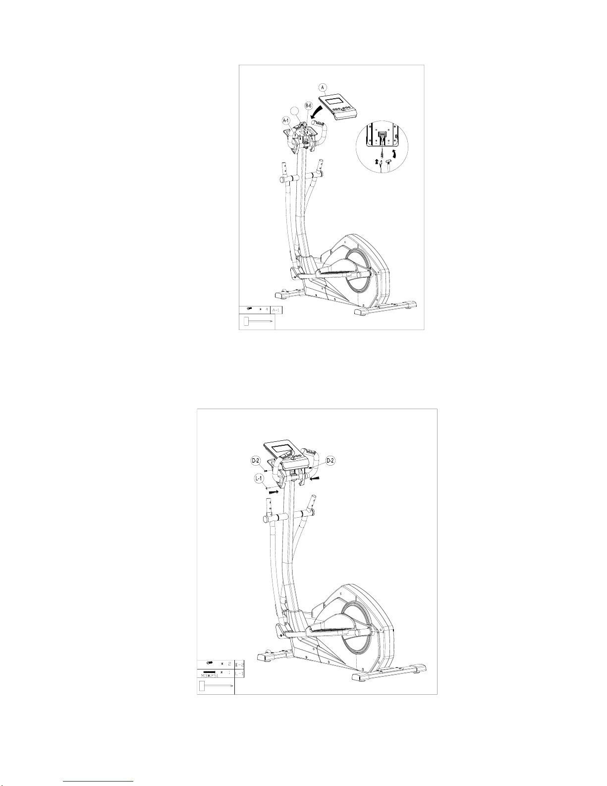
Assembly Stage #8
1. Connect the Computer cables (D-1) and Hand pulse wire (pt.B-6)to the computer, then
attach the Computer (pt .A-1) to the Computer bracket with the enclosed Screws
(pt .A-2).
Assembly Stage #9
1. Please remove four sets of the screw (D-2) from the handlebar post (D).
2. Assemble the console holder cover (D-3,D-4) for the handlebar post (D) by screw (D-2)
D-1
M5*10L
8
M5*12L
9

and self tapping screw (L-1)

Assembly Stage #10
1. Assemble the upper handlebar (C, C-3) by carriage bolts (L-2) with nut (L-3) and
semi-circle washer (L-4).

L-14: Spring
(8)
L-22: flat washer
*1T (4)
L-4:Curved Washer for M8 bolt (4)
L-6:Hex bolt
M8*P1.0*20L(4)
L-8:flat washer 10* *2T (4)
L-9:Curved Washer
17.5* 25*0.3T(4)
L-7:Teflon washer
10* *0.5T (4)
SE01
(8)

L-18:Metal cover (1)
L-20: Spring Washer for
(2)
L-19: flat washer 7* *1T (2)
L-21: Allen Bolt M7*P1.0*30L(2)
L-16: allen bolt M8*P1.25*55L (2)
L-15:Carriage Bolt M6*P1.0*50L (8)
Box Spanner (2)
Allen Key(1)
SE01
L-10:lock nut for M8 (2)
L-2:Carriage Bolt
M8*P1.25*40L (4)
L-3 :Acorn Nut for M8 Bolt (4)
L-11: Allen Bolt
M8*P1.25*16L 8pcs
L-17 Washer
16 t(2) L-1 Screw M3*25L(1)

2017/1/13P16/17
COMPUTER INSTRUCTION MANUAL
[BUTTON FUNCTION]
MODE/ENTER
In stop mode, the mode is to confirm all exercise data setting, and enter into program.
RESET
In stop mode, press the button back to main menu.
START/STOP
To start or stop exercise.
RECOVERY
To test hear rate recovery status.
UP
To select training mode and adjust function value up.
DOWN
To select training mode and adjust function value down.
BODY FAT
For body fat measurement
[DISPLAY EXERCISE DATA]
TIME
Display range 0:00~99:99 ; Setting range 0:00~99:00
DISTANCE
Display range 0.00~99.99 ; Setting range 0.00~99.90km
CALORIES
Display range 0~9999 ; Setting range 0.00~9990
PULSE
Display range P-30~240 ; Setting range 0-30~240
WATT
Display range 0~999 ; Setting range 10~350
SPEED
0~99.9km
RPM
0~999
[OPERATION PROCEDURE]
1. Connect power supply and computer will power on with a long beep sound, LCD display
all segments (FIGURE A) for 2 seconds and enter into personal data setting mode
(gender, age, height and weight) for U1~U4. (FIGURE B~C)
2. After user data set up, computer will display main menu (FIGURE D).
A B
C D
3. In main menu, first exercise program MANUAL will flash, user may press UP and
DOWN button to select MANUAL PROGRAM (12 profiles) (FIGURE E)
PROGRAMUSER PROGRAMHRC (FIGURE F) WATT.

2017/1/13P17/17
E F
4. Quick Start and Manual :
Before exercise in Manual mode, user my set up TIME, DISTANCE, CALORIES and
PULSE target.After power on, user may press START/STOP button to start exercise in
MANUAL immediately without any setting. Level can be adjusted during exercise by
press UP or DOWN.
5. PROGRAM:
Before exercise in Program mode, user may set up TIME target.
Press the UP/ DOWN key to select Program with 12 profiles and press ENTER/MODE
to confirm. Level can be adjusted during exercise by press UP or DOWN.
6. H.R.C.:
Before exercise, computer will ask for user AGE first to calculate TARGET pulse. User
may still press UP and DOWN to change target pulse from 30 to 240.
7. USER PROGRAM:
User may press UP, DOWN and then press MODE to create his own profile. (from
column 1 to column 20) User may hold on pressing MODE button for 2 seconds to quit
profile setting.
8. WATT :
The preset watt value 120 is flashing on screen in WATT setting mode. User may use
UP, DOWN button to set target value from 10 to 350. Press MODE button for confirm.
9. BODY FAT:
9-1 In STOP mode, press the BODY FAT button to start body fat measurement.
9-2 Then selected user (U1~U4) will blinking for 2 seconds. Then start measuring.
9-3 During measuring, user has to hold both hands on the handgrip. And the LCD will
display “--” “--“for 8 seconds until computer finish measuring.
9-4 LCD will display BODY FAT advice symbol, BODY FAT percentage, BMR, BMI for
30 seconds.
10. RECOVERY:
After exercising for a period of time, keep holding on handgrips and press
“RECOVERY” button. All function display will stop except “TIME” starts counting down
from 00:60 to 00:00.
Screen will display your heart rate recovery status with the F1, F2….to F6. F1 is the
best, F6
F6 is the worst. User may keep exercising to improve the heart rate recovery status.
(Press the RECOVERY button again to return the main display.)
NOTE:
1. This computer requires 9V, 0.5mA adaptor.
2. When user stop pedaling for 4 minutes, computer will enter into power save mode, all
setting and exercise data will stored until user start exercise again.
3. When computer act abnormal, please plug out the adaptor and plug in again.
Table of contents
Popular Elliptical Trainer manuals by other brands

ASUNA
ASUNA 4300 owner's manual

Domyos
Domyos VE 710 Assembly instruction

SPORTS ART
SPORTS ART E83 manual

Horizon Fitness
Horizon Fitness CLUB SERIES CSE3.6 user guide

Cosco Fitness
Cosco Fitness FURY 58 owner's manual
ICON Health & Fitness
ICON Health & Fitness NordicTrack Freestride Trainer FS10i user manual


