OM-NI 2/20
18
YEARLY
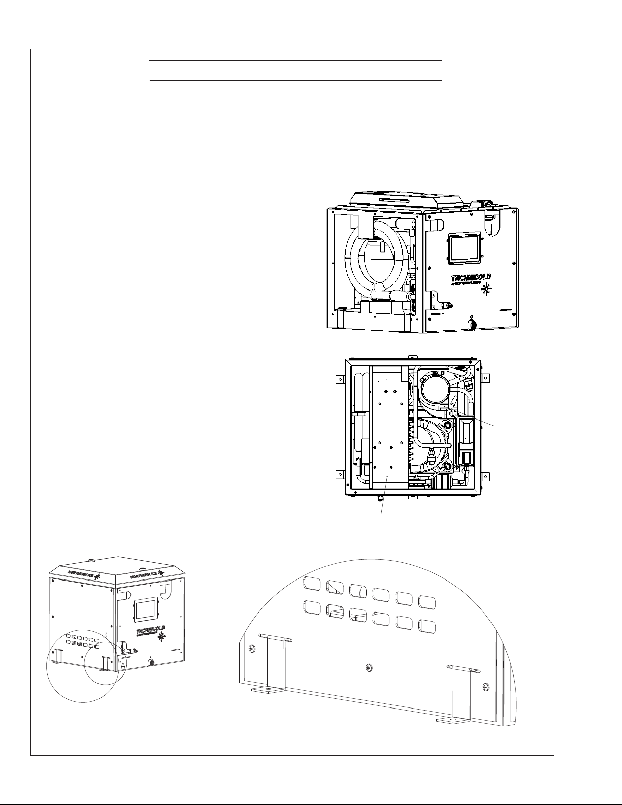
• Condenser Coils
Back ush condenser coils annually, or more frequently
depending on water quality. Periodically chemical clean-
ers are needed to remove marine growth or scale. Consult
the condenser coil cleaning section for instructions on
chemically cleaning the coils. We recommend that certi-
ed technicians perform this service.
Condenser Coil & Raw Water System Cleaning
Prior to cleaning the condenser coil or raw water piping
take baseline readings such as refrigerant pressures,
amperages and the temperature of each condenser coil
wrap.
Turn o the unit and raw water pump. Close the thru-hull
valve.
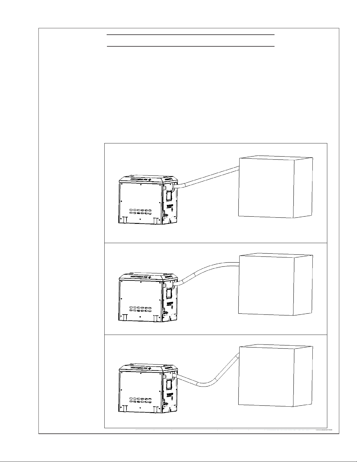
The entire raw water system can be ushed at the same
time. However, the most eective way to clean the system
is to isolate each section (condenser, manifold, piping)
and clean individually.
Before using chemicals to clean the system it should be
back-ushed with fresh water into a container. The pres-
sure generated from the dockside water connection or the
onboard fresh water pump is usually greater than what is
generated by the system's raw water pump. This pressure
can usually ush out a signicant amount of debris and
contaminants from inside the system.
After the back-ushing; the system should be checked
again to see if there was a change in the baseline read-
ings. If within the normal range then no further cleaning
is needed.
Back-ushing with fresh water should be part of your
maintenance schedule. The frequency is dependent on
the usage of the system and water conditions in the areas
where the boat operates. It may only require it once a year
or every 3 months. In harsh conditions it may be required
more frequently.
If the back-ushing has minimal impact on the system
cleanliness then chemical cleaning is needed.
There are numerous chemicals available for cleaning raw
water systems onboard vessels. Some are environmentally
friendly and some are more aggressive. Any chemical or
mix used for the cleaning of the system must be captured
and disposed of in accordance with Federal, State and/or
Local Regulations.
Maintenance
Follow all directions and warnings provided by the manu-
facturer of the chemical. Safety equipment and clothing
must be used to protect personnel and prevent damage to
the surrounding area or equipment.
Chemical cleaners are available at local Marine Whole-
salers, Online or at Commercial Supply Houses. When
selecting a cleaner make sure it is compatible with the
materials in the raw water circuit. Some cleaners are made
to clean a specic contamination such as Algae or Crusta-
ceans and Calcication, some clean a broad spectrum of
contaminants.
Some chemical manufacturers have a cleaning kit avail-
able for purchase. It usually includes a chemical container
with hose connections, hose, chemical pump, lter, and
other miscellaneous items. You could also make up your
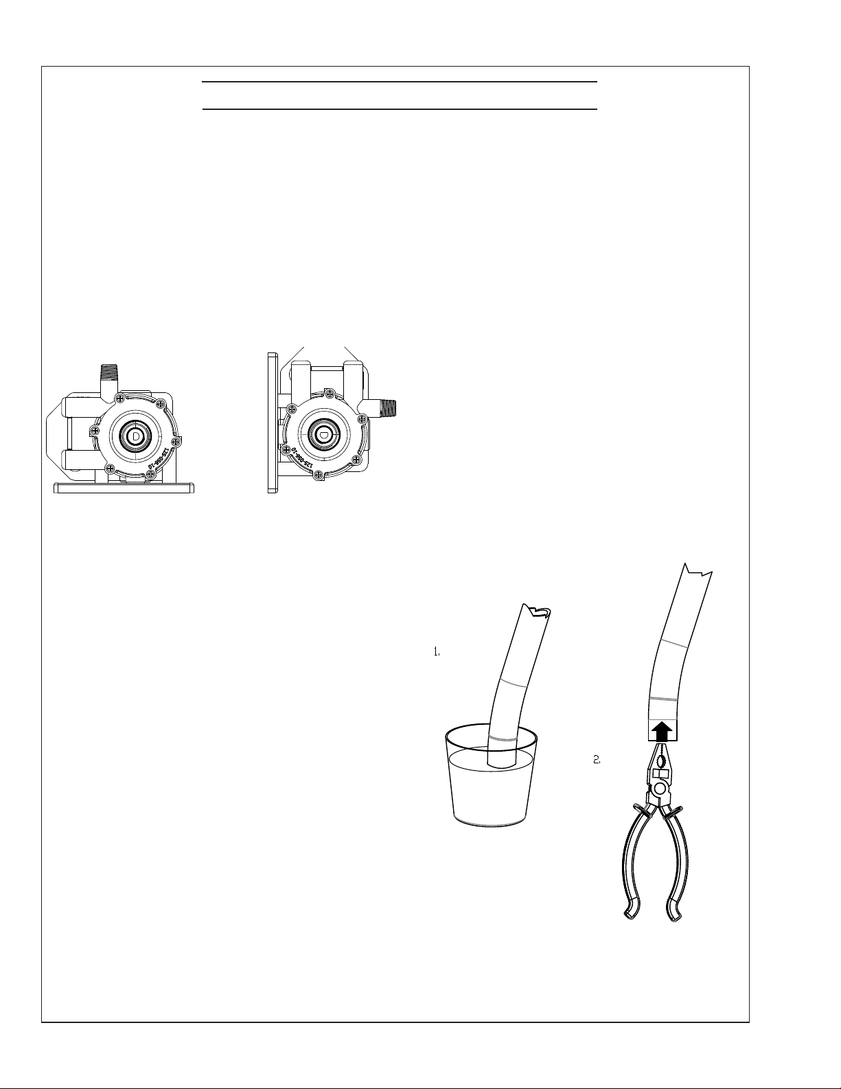
own kit. A Technicold TE500 pump is a good quality,
chemical resistant, submersible pump that can be used
for this purpose. When using any pump for cleaning, a
strainer/lter/screen must be installed on the inlet of the
pump to prevent debris from damaging the impeller.
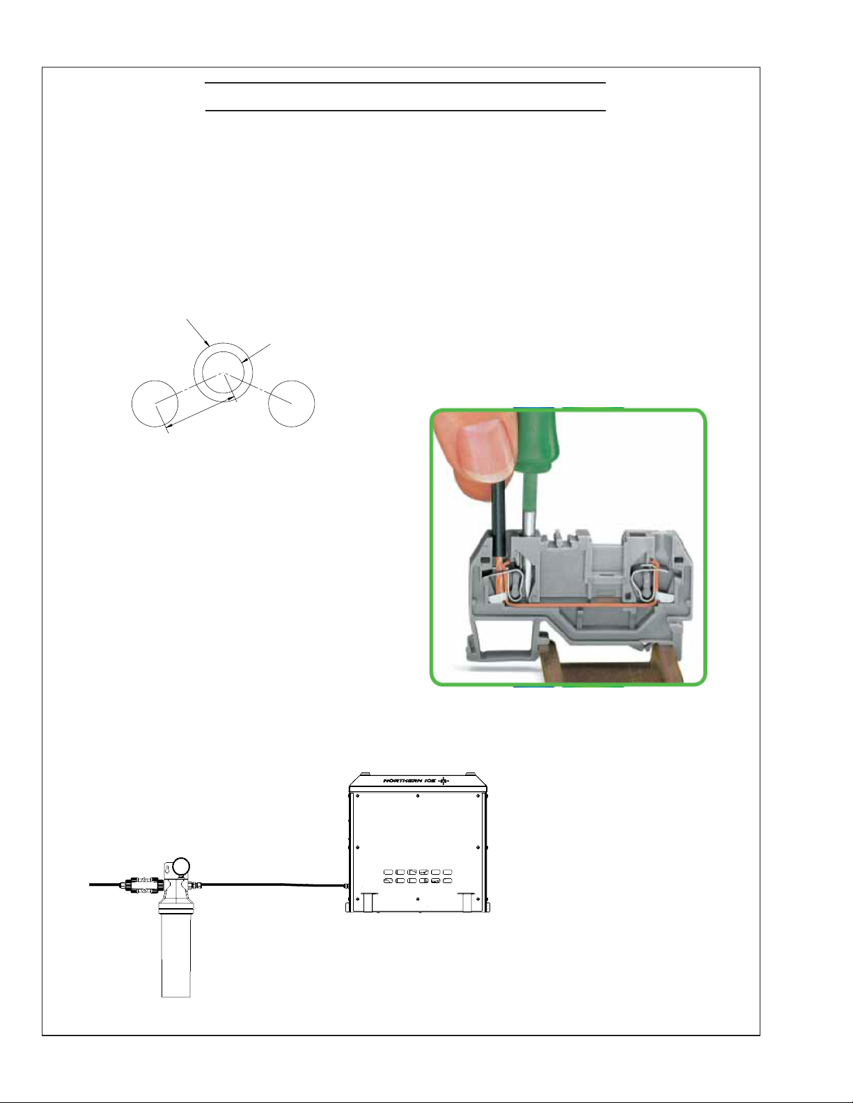
The container should be of sucient volume for the
chemical/water mix required. The chemical pump can be
placed outside of the container. A bulkhead tting would
be installed in the side of the container and a hose con-
nected from it to a strainer, then to the inlet of the pump.
Connect a hose from the discharge of the pump to the
inlet of the coil/manifold/piping to be cleaned. Another
hose goes from the outlet of the coil/manifold/piping back
into the bucket. If using a submersible pump a bulkhead
tting is not needed. The pump can be placed directly in
the container with a strainer/lter/screen attached to the
inlet. Check the ltration on the inlet of the pump regu-
larly and clean as needed.
Make sure that any materials used (container, hoses, t-
tings, pump, etc.) to ush the system are compatible with
the chemical used.
Use caution when mixing the chemical and water that you
do not splash it on yourself or the surrounding area.
Once you have set up your cleaning kit it should be oper-
ated with fresh water to check for leaks prior to adding the
chemical mix. Protect the area where you are working to
prevent damage from splashing or spilled chemical.