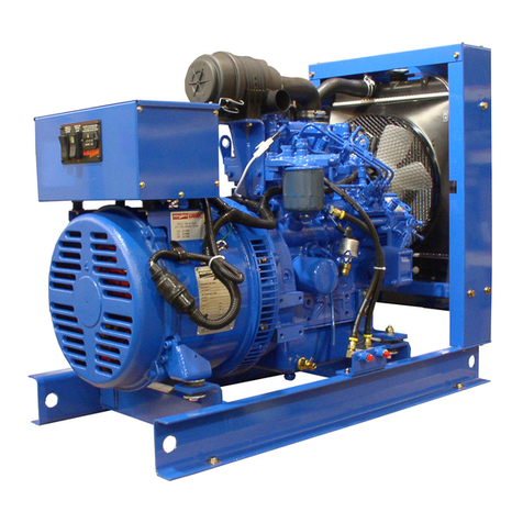
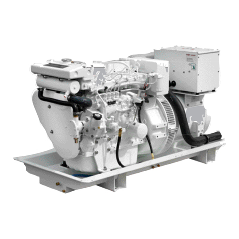
Northern Lights Lugger M773LW3 User manual

OPERATOR’S MANUAL
OPERATOR’S MANUAL
OM773LW3
For Model: M773LW3 and M773LW3G
www.northern-lights.com

Breathing Diesel engine exhaust and some of its constituents
are known to the State of California to cause cancer, birth
defects, and other reproductive harm.
* Always start and operate the engine in a well-ventilated area.
* If in an enclosed area, vent the exhaust to the outside.
* Do not modify or tamper with the exhaust system.
* Do not idle the engine except as necessary.
For more information, go to www.P65warnings.ca.gov/diesel.
— CALIFORNIA —
Proposition 65 Warning:
Northern Lights
4420 14th Avenue NW
Seattle, WA 98107
Tel: (206) 789-3880
Fax: (206) 782-5455
Copyright ©2019 Northern Lights, Inc.
All rights reserved. Northern Lights™, and
the Northern Lights logo are trademarks of
Northern Lights, Inc.
Printed in U.S.A.
PART NO.: OM773LW3 11/20

OM773LW3 11/20
1
Read this operator's manual thoroughly before starting to operate your equipment.
This manual contains information you will need to run and service your new unit.
OPERATOR'S MANUAL
for Model
M773LW3 and M773LW3G
INTRODUCTION ..................................................2
Models Included .................................................2
UnitIdentication...............................................2
SerialNumbers ...................................................2
WARRANTY ...........................................................3
SAFETY RULES..............................................3 - 7
LOCK OUT / TAG OUT PROCEDURES .......... 8
COMPONENT LOCATIONS
M773LW3GMarineGenerators...................... 10
M773LW3MarineGenerators..........................11
CONTROL PANELS
Series 1-B......................................................... 12
Series 3............................................................. 12
Series 4............................................................. 12
OPERATING PROCEDURES
Break-inPeriod................................................ 13
BeforeStarting................................................. 13
Starting............................................................. 13
Operating ......................................................... 13
Stopping........................................................... 13
ShutdownsandAlarms .................................... 14
SpareParts ....................................................... 14
SERVICING SCHEDULE CHART ................. 15
SERVICING
Lubrication-General....................................... 16
CheckingOil.................................................... 16
OilChanges ..................................................... 16
ChangingLubeOilFilter................................. 16
AirCleaner....................................................... 17
V-Belts ............................................................. 17
ValveClearances.............................................. 17
Fuels-General................................................. 18
FuelFilters ....................................................... 18
CoolingSystem-General................................ 19
Checkingcoolantlevel ................................... 19
CoolingSystemFlushing................................. 19
InjectorService................................................ 20
InjectionPump................................................. 20
HeatExchanger............................................... 22
RawWaterPump ............................................. 22
ExhaustElbow ................................................ 22
GeneratorEnds ................................................ 22
ElectricalSystem-General ............................. 22
GlowPlugs....................................................... 22
BoosterBatteries.............................................. 23
BatteryCare ..................................................... 23
Winterizing/Out-of-Service ........................... 23
TROUBLESHOOTING
Electrical .......................................................... 24
Engine ...................................................... 25 - 27
BleedingtheFuelSystem ................................ 28
WIRING DIAGRAMS (Current Production)
ACElectrical ........................................... 30 - 33
DCElectrical ........................................... 34 - 42
PanelWiring ............................................ 43 - 45
APPENDIX (Non-Current Production Diagrams)
DCElectrical ........................................... 46 - 49
PanelDiagrams........................................ 50 - 54
Proprietary Information
ThispublicationisthepropertyofNorthernLights,Inc.
ItmaynotbereproducedinwholeorinpartwithoutthewrittenpermissionofNorthernLights,Inc.
©NorthernLights,Inc.Allrightsreserved.LithoU.S.A.PublicationnumberOM773LW311/20
Table of Contents

OM773LW3 11/20
2
Servicingofmarineenginesandgeneratorsets
presentsuniqueproblems.Inmanycasesboats
cannotbemovedtoarepairfacility.Marineengines
cannotbecomparedtotheservicingofautomobiles,
trucksorevenfarmequipment.Failuresoftenoccur
inremoteareasfarfromcompetentassistance.
Marineenginesaretaxedfarmoreseverelythan
autoortruckengines;therefore,maintenancesched-
ulesmustbeadheredtomorestrictly.
Failuresbeginwithminorproblemsthatareover-
lookedandbecomeampliedwhennotcorrected
duringroutinemaintenance.
Asoperator,itisyourobligationtolearnaboutyour
equipmentanditspropermaintenance.Thisisnota
comprehensivetechnicalservicemanual.Norwillit
makethereaderintoanexpertmechanic.Itsaimis
toaidyouinmaintainingyourunitproperly.
Introduction
L, W, G, 3
M - Northern Lights marine
generator set
Model number of engine block
Bore Cylinders
77 mm 3
MODELS INCLUDED
Thismanualcoverstheoperatinginstructionsfor:
M773LW3 and M77LW3G marine generator setsthe
unit'application,blockmodel,aspiration,andRPM:
L- Long stroke
W- Auxiliary Winding in Generator
End
G- GEM series base frame
3 - US EPA Tier III compliant
++
Northern Lights marine generator set with a 773 engine, PX-309K2 generator end, AVR, US EPA Tier III.
M 773
M773LW3 =
Yoursethasthreeserialnumbers:1anenginenumberstamped
ontheblock,2 ageneratorplate,and3ageneratorsetplate.
Usetheserialnumberonthegeneratorsetplatewhenorderingparts
orincorrespondence.Thegeneratorsetplateisfoundontheservice
sideofthegeneratorandresemblesthedrawinginFigure 1.
Unit Identication
Serial Numbers
Model numbers give the unit’s application, block model, aspiration, and RPM
Northern Lights marine diesel generator set with a 773 engine, PX-309K2 generator end, GEM series,
US EPA Tier III.
M773LW3G =
Updated 7-6-18

OM773LW3 11/20
3
Awarrantyregistrationcerticateissuppliedwithyourset.Itentitlestheoriginalpurchaserofourequipment
toawarrantycoveringmaterialorassemblyfaults.TheextentofcoverageisdescribedintheLimitedWarranty
Statement.Werecommendthatyoustudythestatementcarefully.
NOTE:Ifthewarrantyistoapply,theservicinginstructionsoutlinedinthismanualmustbefollowed.Iffurther
informationisneeded,pleasecontactanauthorizeddealerorthefactory.
Safety Rules
Warranty
Updated 8-14-19
NOTICE: Accident reports show that careless use of engines causes a high percentage of accidents.
You can avoid accidents by observing these safety rules. Study these rules carefully and enforce them on the job.
IMPORTANTSAFETYINSTRUCTIONS.
Electromagneticequipment,includinggeneratorsets
andtheiraccessories,cancausebodilyharmand
lifethreateninginjurieswhenimproperlyinstalled,
operatedormaintained.Topreventaccidentsbeaware
ofpotentialdangersandactsafely.
READANDFOLLOWALLSAFETY
INSTRUCTIONSINTHISMANUAL,
PRIORTOTHEINSTALLATION
OFANYGENERATORSETOR
ACCESSORY.KEEPTHESE
INSTRUCTIONSFORFUTURE
REFERENCE.
Recognize Safety Symbols and Instructions
Inadditiontotheinformationfoundinthissection,this
operator’smanualusesthreedierentsignalwordsto
outlinepotentialdangersofaspecicnature.
Follow All Safety Instructions
Carefullyreadandunderstand
allsafetymessagesinthis
manualandonyourmachine’s
safetysigns.Keepsignsin
goodandcleancondition.
Replacemissingordamaged
signs.Besurenewequipmentcomponentsand
repairpartsincludethecurrentsafetysigns.For
replacementsigns,properplacementofsafetysigns
orclaricationonanysafetyissue,consultyour
NorthernLightsdealerorthefactory.
Therecanbeadditionalsafetyinformationcontained
onpartsandcomponentsfromoutsidesuppliers
thatisnotreproducedinthismanual.Consultthe
suppliersforadditionalsafetyinformation.
Learnhowtooperatethemachineandhowtouse
thecontrolsproperly.Onlytrainedpersonnelshould
operatemachines,orworkonoraroundthem.
Keepyoumachineinproperworkingcondition.
UNAUTHORIZEDMODIFICATIONSTOTHE
MACHINERYMAYIMPAIRITSFUNCTION
ANDSAFETYPARAMETERS.
Prevent Bypass and Accidental
Starting
!
WARNING
Donotstartenginebyshortingacrossstartterminal.
Enginewillstartifnormalcircuitryisbypassed,
creatingahazardbyrunawaymachinery.
Startengineonlyfromoperator’sstation.
!
DANGER
!
WARNING
!
CAUTION
DANGERindicatesahazardoussituationwhich,if
notavoided,willresultindeathorseriousinjury.
WARNINGindicatesahazardoussituationwhich,if
notavoided,couldresultindeathorseriousinjury.
CAUTIONindicatesahazardoussituationwhich,
ifnotavoided,couldresultinminorormoderate
injury.
DANGER: Northern Lights generator sets and /or any other diesel powered equipment provided by NLI is not provided
with ignition protected components, and therefore is not to be installed in the presence of combustible gases having a
ash point of 43.3 Degrees C (110 Degrees F) or lower, such as Gasoline, Propane, Natural Gas or other similar fuel
sources.

OM773LW3 11/20
4
Safety Rules (Continued)
Updated 4-12-17
Wear Protective Clothing
!
WARNING
Topreventcatchinganythinginmovingmachinery,
alwayswearclosettingclothesandsafety
equipmentappropriate
tothejob.
Prolongedexposure
toloudnoisecan
causehearinglossor
impairment.Wear
suitableauthorized
hearingprotection,
suchasearmusorplugstoprotectagainstloud
noises.
Operatingequipmentrequiresthefullattentionofthe
operator.Donotuseradioormusicheadphones
whileoperatingmachinery.
Practice Safe Maintenance
!
CAUTION
Understandallservice
proceduresbeforestartingwork.
Keepareacleananddry.Neverlubricate,service,or
adjustmachinewhileitisinoperation.
Keephands,feetandclothingawayfrompower-
drivenequipment.Whenshuttingdownanengine,
disengageallpowerandoperatorcontrols.Allow
theenginetocoolcompletelybeforebeginningany
servicework.
Securely support any machinery elements that must
be raised for service work with support or lifting
machinery specically intended for that purpose.
Keepallpartsingoodconditionsandproperly
installed.Fixdamageimmediately.Replaceany
wornorbrokenparts.Removeanybuildupof
grease,oilordebris.
Disconnectbatterygroundcable(-)beforemaking
anyadjustmentsorservicework.
Handle Fuel Safely - Avoid Flames
!
WARNING
Dieselishighlyammableandshouldbetreatedwith
careatalltimes.Dodonotrefuelwhilesmokingor
whennearsparksoropename.
ALWAYSSTOPENGINEBEFOREFUELING
MACHINE.Alwaysll
portablefueltankoutdoors.
Neverfuelahotengine.
Preventaccidental
dischargeofstartinguids
bystoringallcansina
cool,safeplace,away
fromsparksoropename.Storewithcapsecurely
oncontainer.Neverincinerateorpunctureafuel
container.
Preventresbykeepingmachinecleanofaccumulated
trash,greaseanddebris.Alwayscleananyspilledfuel
asswiftlyaspossible.Donotstoreoilyrags,which
canigniteandburnspontaneously.
Bepreparedifarestarts.Keeparstaidkitandre
extinguisherhandy.Keepemergencycontactnumbers
forredepartment,doctors,ambulanceandhospital
nearthetelephone.
Service Machines Safely
!
DANGER
Donotwearanecktie,scarf,necklace,ringsorother
jewelry,oranylooseclothing
whenworkingnearmoving
parts.Tielonghairbehindyour
head.Ifanyoftheseitemsget
caughtinmovingmachinery,
severeinjuryordeathcould
result.
Checkforanylooseelectricalconnectionsorfaulty
wiring.
Lookcompletelyaroundenginetomakesurethat
everythingisclearbeforestarting.

OM773LW3 11/20
5
Stay Clear of Rotating Drivelines
!
DANGER
Entanglementinrotating
drivelinescancauseserious
injuryordeath.Keep
shieldsinplaceatalltimes.Makesurethatrotating
shieldsturnfreelyinpacewiththedrivelines.
Donotwearloosettingequipmentaroundrotating
drivelines.Stoptheengineandmakesurethat
allmovingpartshavestoppedbeforemakingany
adjustments,connections,orperforminganyothertype
ofservicetotheengineorotherdrivenequipment.
Install all Safety Guards
!
WARNING
Directcontactwithrotating
fans,belts,pulleyanddrives
cancauseseriousinjury.
Keepallguardsinplace
atalltimesduringengine
operation.
Wearclose-ttingclothes.Stoptheengineandbe
sureallfans,belts,pulleysanddrivesarestopped
beforemakingadjustments,connections,orcleaning
nearfansandtheircomponents.
Donotallowanythingonyourpersontodangleinto
orcomeincontactwithamovingfan,belt,pulleyor
drive.Fanscanactasvacuumsandpullmaterials
upfrombelow,soavoidthatareaaswellwhilein
service.
Safe Battery Handling
!
WARNING
Prevent Battery Explosions
Batterygasishighlyammable.Batteryexplosions
cancausesevereinjuryordeath.Tohelpprevent
batteryexplosions,keepsparks,lightedmatches
andopenameawayfromthetopofbattery.When
checkingbatteryelectrolytelevel,useaashlight.
Safety Rules (Continued)
Updated 4-12-17
Nevercheckbatterycharge
bycontactingthepostswith
ametalobject.Useavolt-
meterorhydrometer.
Frozenbatteriesmayexplode
ifcharged.Nevercharge
abatterythathasnotbeen
allowedtowarmtoatleast
16oC(60oF).
Alwaysremovegrounded(-)batteryclamprstand
replacegroundclamplast.
S
ulfuricacidinbatteryelectrolyteispoisonousand
strongenoughtoburnskin,eatholesintoclothingand
othermaterials,andcauseblindnessifsplashedintoeyes.
To Avoid Hazards:
•Fillbatteriesonlyinwell-ventilatedareas.
•Wearappropriateeyeprotectionandrubbergloves.
•Neveruseairpressuretocleanbatteries.
•Wearappropriateventilationequipmenttoavoid
inhalingfumeswhenaddingelectrolyte.
•Donotspillordripelectrolyte.
•Usecorrectjump-startprocedureifrequired.
If acid is spilled on skin or in eyes:
1.Flushskinwithwater.
2.Applybakingsodaorlimeto
helpneutralizeacid.
3.Flusheyeswithwaterfor
15-30minutes.
4.Getmedicalattention
immediately.
Ifacidisswallowed:
1.DONOTinducevomiting.
2.Drinklargeamountsof
waterormilk,without
exceeding2liters
(2quarts)
3.Getmedicalattention
immediately
Batteryposts,terminals,andrelatedaccessories
cancontainleadandleadcompounds,chemicals
knowntotheStateofCaliforniatocausecancerand
reproductiveharm.Washhandsafterhandling.
!
WARNING

OM773LW3 11/20
6
Safety Rules (Continued)
Updated 4-12-17
Donotuseachlorinatedsolventinanareawhere
weldingwilloccur.Workonlyinareasthatarewell
ventilated.Disposeofpaintandsolventproperly.
Service Cooling System Safely
!
WARNING
Openingapressurizedcooling
systemcanreleaseexplosiveuids
andcausingseriousburns.
Beforeopeninganypressurized
coolingsystem,makesurethe
enginehasbeenshuto.Do
notremoveallercapunlessit
iscoolenoughto
comfortablygripwithbarehands.Slowlyloosencapto
relievepressurebeforeopeningfully.
Avoid High Pressure Fluids
!
WARNING
Relievepressurepriorto
disconnectingpressurized
lines.Escapinguidunder
pressurecanpenetratethe
skincausingseriousinjury.
Alwaysrelievepressurebeforedisconnecting
hydraulicorotherpressurizedlines.Tightenall
connectionsrmlybeforere-applyingpressure.
Ifsearchingforleaks,useapieceofcardboard.
Alwaysprotectyourhandsandotherbodypartsfrom
high-pressureuids.
Ifanaccidentoccurs,seeadoctorimmediately.Any
highpressuresprayinjectedintotheskinmustbe
removedwithinafewhourstopreventtheriskof
gangreneorotherinfection.
Avoid Heating Near Pressurized Fluid Lines
!
WARNING
Flammablespraycanbegenerated
byheatingnearpressurizeduid
lines,resultinginsevereburnsand
bodilyinjury.Pressurizedlines
canrupturewhenheatgoesbeyond
theimmediateamearea.Donotweld,solderoruse
atorchoropenamenearpressurizedlinesorother
ammableuids.
Handle Chemical Products Safely
!
WARNING
Directexposuretohazardous
chemicalscancauseserious
injury.Amongthepotentially
hazardouschemicalsthatmaybe
usedwithNorthernLights
productsarelubricants,coolants,
paintsandadhesives.
AllpotentiallyhazardouschemicalscomewithaMaterial
DataSafetySheet(MSDS).TheMSDSprovidesspecic
detailsonchemicalproducts,includingphysicalhazards,
safetyproceduresandemergencyresponsetechniques
ReadandunderstandtheMSDSforeachchemicalbefore
youstartanyjobthatincludesit.Followtheprocedures
anduseappropriateequipmentexactlyasrecommended.
ContactyourNorthernLightsdealerorNorthernLights
factoryforMSDS’susedonNorthernLightsproducts.
Work in Well Ventilated Areas
!
CAUTION
Exhaustfumesfromenginescontaincarbonmonoxide
andcancausesicknessordeath.Workinwellventilated
areastoavoidprolongedexposuretoenginefumes.Ifit
isnecessarytorunanengineinanenclosedarea,route
theexhaustfumesoutoftheareawithanapproved,leak
proofexhaustpipeextension.
Remove Paint Before Welding or Heating
!
WARNING
Hazardousfumescanbe
generatedwhenpaintisheated
bywelding,solderingorusinga
torch.Toavoidpotentiallytoxic
fumesanddust,removepaint
beforeheating.
•
Removepaintaminimumof100mm(4in.)fromthe
areathatwillbeaectedbyheat.
•
Ifpaintcannotberemoved,wearanapprovedrespirator.
•Ifyousandorgrindpaint,useanapprovedrespirator.
•Ifyouusesolventorpaintstripper,removestripper
withsoapandwaterbeforewelding.Remove
solventorpaintstrippercontainersfromthearea.
•Allowatleast15minutesforfumestodisperse
beforeweldingorheating.

OM773LW3 11/20
7
Safety Rules (Continued)
Updated 4-12-17
Avoidcreatingdust.Neverusecompressedairfor
cleaning.Avoidbrushingorgrindingmaterials
containingasbestos.Whenservicing,wearan
approvedrespirator.Aspecialvacuumcleaneris
recommendedtocleanasbestos.Ifthisvacuumisnot
available,applyamistofoilorwateronthematerial
containingasbestos.Keepallbystandersawayfrom
anyareawhereasbestosdustmaybegenerated.
Use Proper Lifting Equipment and Techniques
!
WARNING
Liftingheavycomponentsincorrectly
cancausesevereinjuryordamage
tomachinery.Avoidunbalanced
loads.Donotuseliftingeyes.Lift
thegeneratorsetusingliftingbarsinsertedthrough
theliftingholesontheskid.Followallrecommended
removalandinstallationproceduresinthisand
associatedNorthernLightsmanuals.
Use Proper Tools
!
CAUTION
Makeshifttoolsandprocedures
cancreatesafetyhazards.
Alwaysuseappropriatetoolsforthejob.
Usepowertoolsonlytoloosenthreadedpartsand
fasteners.Forlooseningandtighteninghardware,
alwaysusethecorrectsizedtools.
DonotuseUSmeasurementtoolsonmetric
fasteners,orviceversa.Useonlyservicepartsthat
meetNorthernLightsspecications.
Dispose of Waste Properly
!
CAUTION
Disposingofwasteimproperlycanthreatenthe
environmentandleadtounsafeworkingconditions.
PotentiallyharmfulwasteusedinNorthernLights
equipmentcanincludeoil,fuel,coolant,ltersand
batteries.
Useleakproofcontainerstodrainuid.Donot
usefoodorbeveragecontainersthatmaymislead
someoneintodrinkingfromthem.
Donotpourwasteontotheground,downadrainor
intoanywatersource.
Do Not Open High-Pressure Fuel System
!
DANGER
ManyNorthernLightsenginesusehigh-
pressurefuelinjection.High-pressureuid
remaininginfuellinescancauseserious
injury.Donotdisconnectorattempt
anyrepairoffuellines,sensors,orother
componentsbetweenthehigh-pressurefuelpump
andnozzlesonengineswithhighpressurefuel
systems.
ONLYAUTHORIZEDTECHNICIANSCAN
PERFORMREPAIRSONANHIGHPRESSURE
FUELINJECTIONSYSTEMS.
Avoid Hot Exhaust
!
WARNING
Avoidexposuretoandphysical
contactwithhotexhaustgases.Exhaustparts
andstreamscanreachhightemperaturesduring
operation,leadingtoburnsorotherseriousinjury.
Cleaningexhaustlterscanalsoleadtoexposureto
hotexhaustgasandtheinjuryriskassociatedwith
it.Avoidexposuretoandphysicalcontactwithhot
exhaustgaseswhencleaningexhaustlters.
Duringautoormanual/stationaryexhaustlter
cleaningoperations,theenginewillrunat
elevatedtemperaturesforanextendedperiodof
time.Exhaustpartsandstreamscanreachhigh
temperaturesduringoperation,leadingtoburnsor
otherseriousinjury.
Avoid Harmful Asbestos Dust
!
WARNING
Inhalingasbestosbersmay
causelungcancer.Avoid
breathinganydustthatmay
begeneratedwhenhandling
componentscontainingasbestos
bers,includingsomegaskets.
Theasbestosusedinthesecomponentsisusually
foundinaresinorotherwisesealed.Normal
handlingofthesecomponentsisnotdangerous,
aslongasairbornedustcontainingasbestosisnot
generated.

OM773LW3 11/20
8
General Policy
To avoid dangerous or hazardous situations, refrain from
any of the following:
• Removing or bypassing a guard or other safety device
• Placing any part of your body in a position where you
could be caught by moving machinery.
• Cleaning or oiling machinery when in operation.
• Adjusting circuits, chillers, pumps, air handlers, valves,
circuit breakers or fans while in operation.
• Working on piping or high pressure systems.
Lock Out/Tag Out Instructions -
Electrical Equipment
Be sure the equipment’s ON/OFF switch is in the OFF
position and is unplugged from any electrical source before
attempting to perform any type of work on the equipment.
Obtain an electrical plug cap cover with a lockset. Secure
the plug terminal end using the electrical plug lockout cap.
Lock the cap and retain the key.
If the equipment is directly wired into an electrical box with
a shut o switch, obtain a lock pad and/or the appropriate
colored tags and place the lock and tag through the shut
o lever. Retain the key until the repair is completed and
the machine is safe to start. Be certain the shut o lever
is in the OFF position before restarting. NEVER give a
lock out key to unauthorized personnel.
If the equipment is directly wired into an electrical box
without a shut o switch and lock out capability, then a
circuit breaker lock out will be required. Obtain a circuit
lock and tag set. Install the lock onto the circuit breaker
box. Ensure the unit ON/OFF switch is in the OFF position
before restarting.
Lock Out/Tag Out Instructions -
Pneumatic and Hydraulic Equipment
For servicing pneumatic and hydraulic equipment, the
following additional procedures must be implemented,
following completion of lock out/tag out procedures for
the unit to be serviced:
Shut o air, water or supply valves at the equipment to
be serviced.
Check the local bleed-o point for completed release of
pressurized air, water or oil.
If shutting o of air, water or other material cannot be
achieved at the local supply valve, shut o valves further
back in the system and re-check the bleed-o point until
complete shut-o is achieved.
Ax a DO NOT OPERATE tag to each valve handle that
requires shut o. Each DO NOT OPERATE tag must be
signed and dated by the authorized technician servicing
the equipment.
Lock Out/Tag Out Instructions -
Air Hose Connected Pneumatic Equipment
Equipment connected to the compressed air system
through an air hose with a detachable tting must be
shutdown and unplugged. Excess air must be bled prior
to removing the air hose, prior to any maintenance or
repair activities.
Ax a DO NOT OPERATE tag to the air hose near the
detachable tting. Each DO NOT OPERATE tag must be
signed and dated by the authorized technician servicing
the equipment. Check that the equipment cannot be
operated by activating the ON switch.
Stored Energy
Immediately after applying Lock Out or Tag Out devices,
ensure that all potentially hazardous stored or residual
energy is relieved, disconnected, restrained and otherwise
rendered safe.
Verication of Isolation
Verify the machinery or equipment is actually isolated and
de-energized prior to beginning work on a machine or on
equipment that has been locked out.
Restarting Procedures
Follow the procedures below prior to restoring energy:
• Ensure that all machinery or equipment is properly
reassembled. Inspect the machinery or equipment to
verify non-essential items have been removed.
• Ensure that all personnel are safely outside danger
zones. Notify personnel that lock out/tag out devices have
been removed and energy will be reapplied.
• Only authorized personnel may remove lock out/tag out
devices or notices.
Scope
During maintenance, repairs or retooling of a Northern Lights generator set, simply turning the machine o or unplugging
it while it is being worked on does not give enough protection to others who are not performing the maintenance or
repair. Many serious accidents happen when someone thought the machine was turned o, or all of its energy was
safely blocked or released.
!
CAUTION
!
WARNING
!
WARNING
!
WARNING
!
WARNING
!
CAUTION
!
CAUTION
Lock Out / Tag Out Procedures
Updated 4-12-17

OM773LW3 11/20
9
Notes

OM773LW3 11/20
10
Figure 1 (right): Service side M773LW3G
(S/N: 7732-54637 and above)
17
2 4
35
6
78
10
9
11
12
14
15
16
13
18
19
Marine Generator Component Locations
Figure 2 (left): Non-service side
M773LW3G (S/N: 7732-54367 and above)
20 2021 22
23
25
26
1. Generator control box
2. Coolant recovery bottle
3. Fuel lter
4. Air lter housing
5. Fuel lift pump
6. Fuel injector
7. Lube oil ll, top
8. Coolant ll
9. Injection pump
10. Stop solenoid
11. Lube oil ll, side
12. Sea water pump
13. Lube oil drain
14. Oil dipstick
15. Oil lter
16. Fuel manifold
17. Control panel plug
18. AC circuit breaker for AVR
19. DC circuit breaker
20. Heat exchanger end caps
21. Expansion tank
22. Starter
23. Exhaust elbow
24. Vibration mount
25. Alternator
26. Belt guard
24
1
Updated 10-19-20

OM773LW3 11/20
11
Marine Generator Component Locations
Updated 10-19-20
17
1
345
6
7
8
10
9
11
12
15
16 14 13
18
19
2
1. Generator control box
2. Coolant recovery bottle
3. Fuel lter
4. Air lter housing
5. Fuel lift pump
6. Fuel injector
7. Lube oil ll, top
8. Coolant ll
9. Injection pump
10. Stop solenoid
11. Lube oil ll, side
12. Sea water pump
13. Lube oil drain
14. Fuel manifold
15. Oil dipstick
16. Fuel lter
17. Control panel plug *
18. AC circuit breaker for AVR
19. DC circuit breaker
20. Heat exchanger end caps
21. Expansion tank
22. Starter
23. Exhaust elbow
24. Vibration mount
25. Alternator
26. Belt guard
Figure 3 (right): Service side M773LW3
(up to S/N: 7732-54636)
20 2021 22
23
25
26
24
Figure 4 (left): Non-service side M773LW3
(up to S/N: 7732-54636)
* Shown with round “Merc” style plug. Plug type may vary.

OM773LW3 11/20
12
Figure 6: Series 3 Generator Control Panel
Control Panels
Figure 5: Series 1-B Generator Control Panel
1. SHUTDOWN BYPASS-PREHEAT SWITCH
Therearetwofunctionsbuiltintothisswitch:
1.Preheatsthefuelbeforebeginningthestarting
process.Pressswitch10secondsbefore
attemptingstart-up.
2.Bypassesthesafetyshutdownfeatureduring
startingprocess.Keepswitchengagedwhilestarting
engineandforuptovesecondsafterwards,allowing
oilpressuretobuildbeyondshutdownsetpoint.
2. ENGINE CONTROL SWITCH
Tostarttheengine,holdthisswitchintheSTART
positionuntiltheengineisrunning.
NOTE: Excessive cranking of marine sets equipped
with water lift muer systems can cause engine
damage.
Aftertheenginestarts,releasetheswitchanditwill
returntoRUNposition.Tostoptheengine,holdthe
switchintheSTOPposition.
NOTE: The rocker switch is used on Series 1 panels
only, and has a light that glows when the set is running.
3. HOUR METER
Keepstrackofenginerunningtime.
4. OIL PRESSURE GAUGE
Showstheoilpressureintheenginelubricatingsystem.
5. WATER TEMPERATURE GAUGE
Registersthetemperatureofthecoolingwater.
6. D.C. VOLTMETER OR AMMETER
Whentheengineisstopped,thevoltmeterindicatesthe
conditionofthebattery.Whentheengineisrunning,
thevoltmeterindicatesthevoltageoutputofthe
alternator.
Updated 8-14-19

OM773LW3 11/20
13
BREAK-IN PERIOD
1. Therst100hoursonaneworreconditioned
enginearecriticaltoitslifeandperformance.
2. Operatetheengineundervariousconditions,
particularlyheavyloadstohelpseatengine
componentsproperly.50%loadisrequired;75%is
preferred.
3. Constantlychecktheenginetemperatureandoil
pressuregauges(setswithSeries3or4panels).
4. Oilconsumptionisgreaterduringbreak-inas
pistonringstaketimetoseat.
5. Break-InOilChanges:Changeengineoiland
lterat50hours.Changeoilandlteragainat
100hours,thenatevery200hours(consult
Lubricantssectionforoilrecommendation).
BEFORE STARTING
1. Checkthewaterlevelbyremovingthepressure
capfromtheexpansiontankorradiator.Inorderto
givethecoolingwateranopportunitytoexpand,
theexpansiontankshouldbefull.Overowbottle
shouldbehalffull.
Do not open the ller cap when the engine is
warm. Opening a warm ller cap can cause
severe burns.
2. Checktheoillevelinthecrankcasewiththe
dipstick.Theoillevelmustbeinthewaedareaon
thestick.Neverallowtheleveltogobelowthisarea.
Alwaysaddthesameviscosityofoilasisalreadyin
thecrankcase.Donotremovedipstickwhenengine
isrunning.
3. Checkthefueltanklevelandopenanyfuelvalves.
4. Checkandcleantheseastrainerandreopenthesea-
cock.
5. PlacethebatteryswitchintheONposition.
NOTE: The battery switch must always be kept
ON while the engine is running. If the switch is
turned OFF while the engine is running, the battery
charging regulator could be ruined.
STARTING
1. HoldtheShutdownBypass-Preheatswitchinthe
ONpositionfor10secondsbeforestartingacold
engine.Holdingtheswitchtoolongcanburnoutthe
glowplugs.Thisstepisnotnecessaryiftheengineis
alreadywarm.
2. WhileholdingtheShutdownBypass-Preheatswitch
intheONposition,pushtheEngineControlswitchto
theSTARTposition.
3. Assoonastheenginestarts,releasethestartswitch
andcontinuetoholdthebypass/preheatswitchfor
uptoveseconds.Donotcrankthestarterformore
than10secondsconsecutively.Iftheenginefailsto
startwiththerstattempt,besurethatithasstopped
completelybeforere-engaging.
NOTE: Excessive cranking of the starter on Marine
sets equipped with a water lift muer can cause
engine damage. If the engine does not start after three
10-second cranks, close the sea-cock, and remove the
impeller from the raw water pump. This will prevent
the muer from lling with water and backlling the
exhaust line and engine. Once the engine starts, shut
it o immediately and re-install the impeller and open
the sea-cock. Re-start the engine and check the exhaust
overboard outlet for gushes of water.
OPERATING
1. UnitswithSeries3ControlPanels:checkgauges
often.Oilpressuremustbeabove15PSI.TheD.C.
voltmetershouldreadbetween11and15voltsat80°F
(25°C)ambienttemperature.Thecoolanttemperature
gaugemustbebetween167°Fand194°F(75°Cto
90°C).ChecktheA.C.voltageandfrequencymeters
(Series4panel).Ifthegaugesdeviatefromnormal
levels,shutdownthegeneratorsetandinvestigate.
2. Afterstarting,addelectricalloadupto50%forrst
fewminutes.Loadnormallyafter5minutes.
STOPPING
1. Removeelectricalloadfromthegeneratorset.
2. Runtheenginefora3to5minutecooldownperiod.
3. MovetheEngineControlswitchtotheSTOPposition
momentarily.
4. Closethesea-cock,fuelvalve,andbatteryswitch.
Operating Procedures
Updated 10-19-20
!
DANGER

OM773LW3 11/20
14
SHUTDOWNS AND ALARMS
1. Generatorsetshaveshutdownsystemstostopthe
engineintheeventofhighwatertemperature,lowoil
pressureorhighexhausttemperature.
a. Otheralarmsandshutdownsareavailableas
optionalequipment.
Contact your Northern Lights dealer for
troubleshooting assistance if not equipped with
optional gauge panels.
2. Ifoptionalgaugepanelsareinstalled,dothe
followingwhenyourwarningorshutdownsystemis
activated:
a. Engagethepreheatswitchtocheckthetemperature
gauge,ifinstalled.
b. Ifabove205°F(96°C),usetheTroubleshooting
Guideonpage32toisolatethecauseofthe
overheat.
Do not open the ller cap when the engine is
warm. Opening a warm ller cap can cause
severe burns.
c.Makerepairs.Restartyourgeneratorsetafterthe
temperaturegaugeregistersbelow200°F(94°C).
d. Watchthetemperaturegaugeregularlyand
turnotheunitifthetemperaturerisesabove
205°F(96°C)onMarineunits.Repeattrouble-
shooting.
3. Ifshutdownisactivatedandthetemperaturegauge
showstemperaturewithinnormaltemperaturerange:
a. Thisshutdowncouldhavehappenedbecauseof
atoohighexhausttemperature.Thiscouldhave
beencausedbyadamagedimpellerorapartially
blockedseawaterstrainer.Checktheseawater
strainerrst.Ifitisclear,thencheckthe
conditionoftheseawaterpumpimpeller.
b. Checktheenginecrankcaseoillevel.
c. Iftheoillevelislow,llwithrecommended
lubricatingoilandrestart.Watchtheoilpressure
gaugecarefullyandshutotheengineifitdoes
notshowanormalreading(20-60PSI)aftera
fewsecondsofoperation.
d. Iftheoillevelisnormal,DONOTrestartthe
engine.Callyourdealerforassistance.
SPARE PARTS
NorthernLightsrecommendsthatyoukeepthe
followingsparepartsonhandforeldservice.The
partsareavailablefromyourlocalNorthernLights
dealer.Marinemodelshaveoptional“On-Board-
Kits,”ahandyboxthatcontainsthemostcommon
partsyouwillneed.
NorthernLightsstandardsparepartskit(P/N
38-08605)*
contains:
a. Primaryandsecondaryfuellterelements
b. Oillters
c. Airlterelement
d. Drivebelt
e. Thermostatandgaskets
f. Raw waterpumpimpellerwithgaskets
g.Waterpumpcovero-ring
h. Rockerarmcovergasket
Intendedforlong-distancecruisers,NorthernLights
worldclasssparepartskit(P/N38-08612)*contains:
a. Primaryandsecondaryfuellterelements
b. Oillters
c. Airlterelement
d. Drivebelt
e. Thermostatandgaskets
f. Raw waterpumpimpellerwithgaskets
g.Waterpumpcovero-ring
h. Rockerarmcovergasket
i. Impellerkitwithgasket
j.Injectorassembly
k. 12vglowplug
l.Gasketset
m.Fuelliftpumpandmtg.gasket
n.O-ring
o.Relay,SPDT12v50A
p.Workshopmanual
Operating Procedures
Updated 8-14-19
!
DANGER
*-ForusewithM773LW3andM773LW3Ggeneratorsetswithheat
exchangers.ConsultyourNorthernLightsdealerforyourunit’s
specicsparepartsrequirements.

OM773LW3 11/20
15
Servicing Schedule Chart
Updated 8-14-19
After After Every Every Every Every Every
SERVICE 50 100 100 200 500 1000 2500
POINT PAGE OPERATION DAILY Hours Hours Hours Hours Hours Hours Hours
ENGINE:
SP1 16Check oil level •
SP2 16Change engine oil 1) 4) •• •
SP3 16 Change lube oil lters 1) 4) •••
SP4 17Check air cleaner 1) •
SP417Change air cleaner 1) •
SP5 17 Check V-belt tension 1)
•
SP6 17 Check valve clearance 1) 2) •
FUEL SYSTEM:
SP7 18 Check primary lter (Racor) 2) 3) •
SP8 18 Change primary lter element 2) 3) •
SP918 Change secondary fuel lter 1) 3) •
SP12 20 Check injectors 1) 3) 5) •
SP13 20 Check fuel injection pump 6) •
COOLING SYSTEM:
SP10 19 Check cooling water level •
SP11 19 Check and ush cooling system •
SP14 22 Check and clean heat exchanger •
SP15 22 Change impeller in raw water pump 1) 3) •
SP16 22 Check exhaust elbow •
ELECTRICAL SYSTEM:
SP17 23 Check electrolyte level in batteries 1) •
SP18 23 Check condition of batteries 1) •
OUT OF SERVICE:
SP19 23 Winterizing or out-of-service 3)
TheServicingScheduleChartbelowshowstheserviceschedulerequiredforpropermaintenanceofyourgenerator
set.MoredetailedcoverageofeachServicePoint(SP)islistedonthepagenotedinthe‘page’column.
DAILY:
SP1 Checkoillevelinengine
SP7 Checkprimaryfuellter
SP10 Checkcoolingwaterlevel
AFTER FIRST 50 HOURS:
SP2/3 Changeengineoilandlter
AFTER FIRST 100 HOURS:
SP2/3 Changeengineoilandlter
EVERY 100 HOURS:
SP6 Checkv-belttension
SP17 Checkelectrolytelevelinbatteries
EVERY 200 HOURS:
SP2/3 Changeengineoilandlter
SP4 Checkaircleaner
SP18 Checkconditionofbatteries
EVERY 500 HOURS:
SP8 Changeprimaryfuellterelement
SP9 Changesecondaryfuellter
SP15 Changeimpellerinrawwaterpump
SP16 Checkexhaustelbow
EVERY 1000 HOURS:
SP5 Changeaircleanerelement
SP12 Checkinjectors
EVERY 2500 HOURS:
SP13 Checkfuelinjectionpump
SP11 Checkandushcoolingsystem
SP14 Checkandcleanheatexchanger
1) Perform all maintenance every two years at minimum, even if hour level has
not been reached.
2) Consult manufacturer's maintenance schedule, note on chart.
3) Whenever necessary.
4) After rst 50 hours, then at 100 hours, then every 200 hours.
5) Clean injection nozzles every 1500 hours.
6) For EPA emission standards fuel nozzle needs to be
cleaned every 1500 hours, the fuel nozzle and fuel pump
need to be cleaned, adjusted, or repaired every 3000
hours, and the quality guarantee for these parts is 1500
hours or 2 years.

OM773LW3 11/20
16
Servicing
LUBRICATION - GENERAL
1. Useonlyclean,highqualitylubricantsstoredinclean
containersinaprotectedarea.
2. Theselubricantsareacceptable:
a.APIServiceCJ/CK15-40singleviscosityoils.
b.APIServiceCJ/CK15-40multi-viscosityoils.
3. Usetheproperweightoilforyouraverageoperation
temperature.
Figure 7: Lube Oils
4. Someincreaseinoilconsumptionmaybeexpected
whenSAE5WandSAE5-20Woilsareused.Check
oillevelfrequently.
5. Neverputadditivesorushingoilincrankcase.
SP-1. CHECKING OIL LEVEL
1. Checktheoillevelinthecrankcasewiththedipstick.
Theoillevelmustbeinthewaedarea
onthestick.Neverallowtheleveltogobelowthis
area.Followthelubricationrecommendationsabove.
SP-2. OIL CHANGES
1. Thesetisdeliveredwithspecialbreak-inoil.
Changetheengineoilandoillterafter50hours
ofoperation.Usediesel-ratedbreakinoil(JohnDeere
pre-packagedorequivalent)duringtherst100hours.
Consultyourdealerformoreinformation.
2. Changetheoilandlteragainat100hoursusingthe
oilrecommendedinFigure7.Afterthis,changeoil
andlterevery200hours.
3. Duringintermittentcoldweatheroperation,changeoil
every100hoursorsixweeks,whichevercomesrst.
4. Changeoilatanyseasonalchangeintemperature
whenanewviscosityofoilisrequired.
5. Changeoilwhenengineiswarm.
6. Disposeofwasteoilinanapprovedmanner.
7. Neveruseaushingoil.
8. Loosentheclampontheoilchangetube.Removecap.
Drainoil.Replacethecapandtube.
9. Rellenginewithrecommendedoil.
10.Enginecapacitywithnewoillteris:
M773LW3(G) - 4.75 quarts (4.9 liters)
SP-3. CHANGING LUBE OIL FILTER
1. Changethelubeoillterwitheveryoilchange.
2. Usealterwrenchtoremoveoldlter.Disposeof
lterinapprovedmanner.
3. Makesurethegasketfromtheoldlterisremoved
anddiscarded.Cleanmountingsurface.
4. Spreadathinlmofengineoilontherubbergasket
onthenewlterandscrewitonnippleuntilgasket
meetsthesealingsurface.
5. Usinghandsonly–nowrench–tightenlter
one-halfturnfarther.Overtighteningcando
damagetolterelement.
6. Fillenginewithrecommendedoil.Startengineand
checkforleakage.Stopengine,wait3minutes,and
checkoillevel.Addadditionaloilifnecessary.
7. Oillterpartnumbersare:
M773LW3(G) - #24-02002
Air Single Multi-
Temperature Viscosity Viscosity
Above 32°F SAE 30W SAE 15-40W
(0°C)
-10 to 32°F SAE 10W SAE 10-30W
(-23 to 0°C)
Below -10°F SAE 5W SAE 5-20W
(-23°C)
Updated 11-2-20

OM773LW3 11/20
17
SP-4. AIR CLEANER
1. Inspectaircleanerevery200hours.Industycondi-
tions,checkmoreoften.
2. Ifdirty,washelementinsoapywater.Rinseanddry
thoroughlybeforere-installing.
Replaceifnecessary.Partnumbersare:
M773LW3 – #24-28602
NOTE: Failure to change air cleaner at recommended
times can cause severe engine damage. Change
every 1000 hours or two years, whichever comes
rst.
NOTE: Make absolutely sure no impurities enter the
engine while changing the element. Do NOT run the
engine with the air cleaner removed.
SP-5. V-BELTS
1. CheckthetensionandwearontheV-beltdaily.
2. Useyourthumbtopressonthebeltatthemidpoint
betweenthecrankshaftandalternatorpulleys.The
tensioniscorrectifthebeltcanbedepressedabout
3/16in.(5mm).
Servicing
Figure 8: Valve Adjustment
SP-6. VALVE CLEARANCES
1. Adjustvalveclearanceafter1000hoursorasneeded.
2. TobringtheNo.1cylindertotopdeadcenterinthe
compressionstroke,alignthetimingmark;thetop
markofthecrankpulleywiththatofthetiminggear
case.Removetherockerarmcoverandturnthe
crankshaftfowardandbackward.Iftheinletand
exhaustvalvesoftheNo.1cylinderdonotmoveitis
intopdeadcenterposition.Whenthevalvesmove,
orrock,turnthecrankshaftonefullturnandalignthe
topmarkofthecrankpulleywiththetopmarkofthe
timinggearcase.
3. Loosenthelocknutandadjusttheclearancebetween
therockerarmandvalveguideofboththeintakeand
exhaustvalveswiththeadjustmentscrew(Figure 10).
Clearanceonbothintakeandexhaustvalvesshouldbe
0.008in.(0.2mm).
4. Repeatsteps3and4foreachcylinder.Eachsetof
valvesmustbeadjustedindividually.
5. Replacetherockerarmcover.Tightencovernutsto
5-8ft/lbs(0.8-2.3kg/m).
Figure 9: Timing Mark
Cylinder No. 1 2 3
Valve Arrangement Int. Exh. Int. Exh. Int. Exh.
When No.1 cylinder
is at Top Dead Center
in the compression
stroke
With the crankshaft
turned 3600in
normal direction from
above
Valve Arrangement
Updated 8-14-19

OM773LW3 11/20
18
Servicing
FUELS - GENERAL
1. Useonlyclean,highqualityfuelsofthefollowing
specications,asdenedbyASTMdesignationD975
fordieselfuels:
a. Usegradeno.2dieselatambienttemperatures
abovefreezing32°F(0°C).
b. Usegradeno.1atambienttemperaturesbelow
freezing.
2. Uselowsulphurorultralowsulphurfuel.
3. Thecetanenumbershouldbeaminimumof45.
4. DONOTusetheseunsuitablegradesoffuel:
a. Domesticheatingoils,alltypes.
b. ClassBengine.
c. ClassDdomesticfuels.
d. ClassE,F,GorHindustrialormarinefuels.
e. ASTM-D975-60TNo.4-Dandhighernumber
fuels.
5. Storingfuel:
a. Keepdirt,scale,water,andotherforeignmatter
out of fuel.
b. Avoidstoringfuelforlongperiodsoftime.
c. Fillthefueltankattheendofeachday’s
operation.Thiswillreducecondensation.
FUEL FILTERS
1. Yourgeneratorsetshouldhaveaprimaryfuellter
installed.WerecommendtheRacorbrandoffuel
lter-waterseparators.
SP-7. PRIMARY FUEL FILTER
a. Checktheprimaryfuellterdailyas
recommendedbytheltermanufacturer.
Emptythecollectionbowlasnecessary.
SP-8. PRIMARY FUEL FILTER ELEMENT
b. Changetheelementasoftenasnecessaryor
every500hours.
c. Ifthebowlllswithwater,changetheprimary
andsecondaryelementimmediately.
SP-9. SECONDARY FUEL FILTER
2. Changesecondaryfuellterevery500hoursoras
necessary.
a. Removethespin-onlterbyturningit
counterclockwisewithalterwrench.Fillthe
newelementwithfuelandinstallitafter
applyingengineoiltogasketsurface.Screwon
untilthegasketsurfacecomesintocontactwith
sealingsurfaceoflterbase.Then,tightenit
two-thirdsofaturnbyhand.Donotovertighten.
b. Fuellterpartnumberis:
M773LW3(G): #24-52020
Updated 10-19-20
Other manuals for Lugger M773LW3
4
This manual suits for next models
1
Table of contents
Other Northern Lights Engine manuals

Northern Lights
Northern Lights OM944T User manual

Northern Lights
Northern Lights OM844W3 User manual

Northern Lights
Northern Lights OL1276 L1276A2 User manual

Northern Lights
Northern Lights M944T User manual
Northern Lights
Northern Lights TECHNICOLD OM-NI User manual

Northern Lights
Northern Lights OM150C12 User manual

Northern Lights
Northern Lights M843NW3G User manual
Northern Lights
Northern Lights M50C13 User manual

Northern Lights
Northern Lights M80A13S User manual

Northern Lights
Northern Lights NL673L4 User manual
