Northern Telecom DMS-100 Series Operating and installation instructions

NORTHERN TELECOM PRACTICE 297-2011-200
Issued: 88 12 08
Standard
REL.NO. 01.02
Printed in Canada Northern Telecom 1985 Page i
DIGITAL SWITCHING SYSTEMS
DMS-100* FAMILY
INTEGRATED BUSINES
NETWORK SERVICE
BUSINESS SET, GENERAL DESCRIPTION,
INSTALLATION,
Maintenance and Ordering Information
CONTENTS PAGE
* DMS-100 is a trademark of Northern Telecom.
Reason for Reissue: This revised issue replaces the Standard issue dated
86-05-27. The revisions include the addition of Automatic Call Distribution
(ACD) Sets, incorporation of Appendix 1 (Business Sets and Handsets
equipped with TELADAPT* connectors) and numerous other information
updates and corrections. Due to the substantial changes which require
repagination and renumbering of illustrations, revision marks would not be
helpful and are, therefore, not used in this Practice revision.

PRACTICE 297-2011-200
1. OVERVIEW
1.01 The available versions of the Business Set are as follows:
NT4X20AA Business Set without Alphanumeric Display - with
line cord equipped with Teladapt connectors at both
ends and handset cord hardwired to the set.
NT4X20AE Business Set without Alphanumeric Display - with
line cord equipped with Teladapt connector at the
set-end, spade tips at the other end, and handset cord
hardwired to the set.
NT4X20AL Business Set without Alphanumeric Display - both
line cord and handset cord equipped with Teladapt
connectors at both ends.
NT4X20AB Business Set with Alphanumeric Display - with line
cord equipped with Teladapt connectors at both ends
and handset cord hardwired to the set.
NT4X20AF Business Set with Alphanumeric Display - with line
cord equipped with Teladapt connector at the set-end,
spade tips at the other end, and handset cord
hardwired to the set.
NT4X20AM Business Set with Alphanumeric Display - both line
cord and handset cord equipped with Teladapt
connectors at both ends.
NT4X20AT Business Set with Alphanumeric Display for
Automatic Call Distribution (ACD) service. Equipped
with headset jacks at handset side of set. Line cord
and handset cord equipped with Teladapt connectors
at both ends.
BUSINESS SET
WITHOUT
ALPHANUMERIC
DISPLAY
1.02 These business sets (NT4X20AA/AL/AE) are equipped with:
•eight feature or Directory Number (DN) access keys and associated
Liquid Crystal Display (LCD) indicators
•two feature keys without LCD indicators
•four fixed feature keys without LCD indicators (Vol.Up, Vol.Down,
Hold, and Rls)
•a standard 12-button telephone key pad, and
•internal option switches.
1.03 All business sets use voice and “above voice band” signaling
transmission over a 2-wire line. Voice and signaling are frequency division
multiplexed, with binary data transmitted via absence or presence of the carrier
frequency. All feature activation is via this transmission.
Page 1-1

PRACTICE 297-2011-200
Feature Keys,
Assignable 1.04 The feature keys can be assigned a subset of the following features:
Key De- Acro-
signation Feature Description nym
Auto Dial Automatic Dialing AUD
Auto Line Automatic Line AUL
Call Fwd Call Forward CF
Call Park Call Park PARK
Call Wait Call Waiting CWT
Conf Conference Calls CON
Conf3 Three-way Conference TWC
I/C Group Intercom Group GIC
Intercom Intercom Calls ICM
Station.. Station Busy Indication SBI
Msg Wait Message Waiting MWT
Make Busy Make Busy MSB
Override Busy Override EBO
Pickup Call Pickup CPU
Privacy Privacy PRV
Priv Rls Privacy Release PRL
Ring Again Ring Again RAG
Speed Call Speed Call SCS
Time/Date Query Time and Date QTD
Transfer Call Transfer CXR
1.05 LCD indicators associated with the feature keys support the following
four key/LCD states:
FUNCTION LCD STATE
idle or feature inactive LCD off
active or feature active LCD on
incoming call or feature pending LCD flashing (60 IPM)
call on hold LCD winking (120 IPM)
Feature Keys, Fixed 1.06 Non-optional keys on the sets provide three permanent functions; call
Hold, call Release, and Volume Control.
1.07 Hold. The HOLD function has two modes of operation, manual and
automatic. With the user engaged in a call, the call can be put on hold either by
pressing the HOLD key or by pressing another DN key. In either case the DN
LCD indicator changes from ON to “winking” and the user is free to answer or
make another call.
1.08 Release. The RLS (release) key performs the same function as going
on-hook, i.e. when pressed, it terminates a call. The DN LCD indicator
associated with the released call changes from the ON state to the OFF state.
Page 1-2

PRACTICE 297-2011-200
1.09 Volume Control. The speaker volume is controlled by two keys,
VOL UP and VOL DOWN. Operating these keys incrementally increases or
decreases the speaker volume during an ongoing session. The handset receiver
volume is not affected in any way by these speaker volume adjustments. After
session has ended, the speaker volume returns to the default value. The
following adjustments to the default settings are possible:
(a) To change the default value for voice and dial tone, press both the VOL
UP and VOL DOWN keys simultaneously when the signal is present
and after the desired volume level has been obtained. This causes the
current volume setting to be stored as the new default value.
(b) To change the default value of the alerting tone, press the VOL UP or
VOL DOWN keys while the alerting signal sounds. Obtain the desired
level in the same manner as stated above for the speaker volume. The last
set value becomes the new default value.
Note: When the business set is powered down by disconnecting the loop
or the power supply, the voice and dialtone volume returns to the lowest
level, and the alerting tone level goes to the middle point setting when the set
is reconnected.
Basic Features 1.10 Every Business Set has the following basic features:
(a) Automatic Prime DN selection: allows the user to select the prime
DN (i.e., the DN assigned to the 1st key) by going off-hook to answer a
call without pressing a DN key.
(b) On-hook Dialing: allows a call to be dialed by selecting a line and
dialing the number without lifting the handset. The handset must be
lifted once the called party answers.
(c) Listen On Hold: allows the user, when placed on hold, to replace the
handset and listen via the speaker until the other party returns to the call.
(d) Alerting Tones: Warble tone sounds when telephone is on-hook,
buzzer tone sounds when telephone is off-hook.
BUSINESS SET WITH
ALPHANUMERIC
DISPLAY
1.11 In addition to the features provided by the basic business set, the
NT4X20AB, AF and AM sets include a 32-character alphanumeric LCD
display which permits access to the following features:
•Called Number Display
•Calling Number Display
•Query Time and Date (QTD) Display
•Feature Programming
Page 1-3

PRACTICE 297-2011-200
•Feature Usage.
Note: One feature key must be reserved for accessing the QTD display.
Because an LCD indicator is not required for this feature, a feature key
without an associated LCD indicator should be chosen for the QTD display
function. Other features can be assigned, from the switching software, to
function automatically or when called up by operating an assignable function
key. The “Calling Number Display” can be assigned to be activated either at
the first alerting tone, or after the handset (or handsfree option) has been
picked up (or activated). The “Called Number” display is always activated
automatically as dialing takes place.
ACD SET WITH
ALPHANUMERIC
DISPLAY
1.12 The NT4X20AT Automatic Call Distribution (ACD) business set is
intended for use by attendants. It provides head-set and handset capabilities
and makes use of DMS-100 switch software for incoming automatic call
distribution and an optional feature for equal loading of operators. An “agent
jack” (dual PJ327 type) is provided at the handset side of the set to allow
connection of an agent's headset assembly. The ACD business set can be
equipped with up to three 20-key/16-LCD indicator strip add-on units but it
cannot be provided with a Handsfree unit. The ACD set always requires
alternate (external) power. If the alternate power supply fails, the ACD set will
not be operational (no “Fail to POTS”). The following headset is
recommended for use in conjunction with the ACD set:
•Plantronics Supra, HS 0552-1
1.13 The NT4X20AT includes a 32-character alphanumeric LCD screen
which permits access to the following features:
•Called Number Display (BCS-28)
•Calling Number Display
•Query Time and Date (QTD) Display
•Feature Programming
•Feature Usage.
Note: One feature key is required for accessing the QTD display. Because
an LCD indicator is not needed for this feature, a feature key without an
associated LCD indicator should be chosen for the QTD display function.
Other features can be assigned, from the switching software, to function
automatically or when called up by operating an assignable function key.
The “Calling Number Display” can be assigned to be activated either at the
first alerting tone, or after the handset (or handsfree option) has been picked
up (or activated). The “Called Number” display is always activated
automatically as dialing takes place.
20-BUTTON ADD-ON
MODULE 1.14 The NT4X20AC is a 20-key/16-LCD add-on module which extends
the capability of a Business Set by adding more feature key/LCD indicator
strips. It features two rows of 10 keys; the top two keys in each row are not
Page 1-4

PRACTICE 297-2011-200
equipped with LCD indicators and are used for features which do not require
LCD indication (example: QTD key). This add-on unit attaches to the right side
of the business set if only one add-on unit is provided, or to the end of a row of
1 or 2 add-on units (the NT4X20AC is an end-unit which does not allow
further addition of any equipment at the right hand side of the unit).
Note: The NT4X20AC is rated A&M (additions and maintenace). Spare
parts for this module can still be ordered in accordance with Table 5-B.
1.15 The NT4X20AG is similar to the NT4X20AC add-on unit in
appearance and arrangement of key/LCD indicator strips, but can be used either
as an extendable add-on unit or as an end-unit.
AUTO-ANSWERBACK
(AAB) KIT 1.16 The NT4X20AJ Kit contains one NT4X21AD module which mounts
in the Business Set to provide the AAB feature, and two (2) P0180923
mounting screws. The Business Set must be equipped with a Handsfree Unit
when this feature is assigned. This kit cannot be used with the NT4X20AT
ACD business set.
HANDSFREE UNIT 1.17 The NT1L00AA or NT1L05AA Handsfree Units (HFU) are identical
in function to the Companion and Logic Handsfree units, and are designed for
connection to the left side of the Business Sets. Provision is made for:
•accepting incoming calls on either the HFU or the associated business set
•transferring calls between the HFU and the associated business set
•dialing outgoing calls with the handset either on-hook or off-hook
•automatic cutoff of the HFU when the handset is lifted off-hook for
handset operation.
1.18 Controls on the face of the HFU are as follows:
•Volume control: to set the volume of the received signal on the HFU
speaker.
•Indicator lamp: monitors the operating mode of the unit, i.e. the lamp
is on when the unit is in the transmit mode, and off when the unit is in
the receive mode.
•ON key: used to switch on the unit. The key must be depressed
momentarily to answer an incoming call with the handset on-hook or
before commencing on-hook dialing. The key must be held depressed
until the handset is placed on-hook to transfer from handset to handsfree
operation. The key may be held depressed to hold a call on the unit with
both transmission and reception cut off (Note).
•OFF key: used to terminate a call on the HFU (Note).
•MUTE key: used to cut off transmission without affecting reception
(Note).
Page 1-5

PRACTICE 297-2011-200
Note 1: On handsfree units designed for bilingual or international use
(example: NT4X05AA), keys are designated with icons. Refer to Fig. 1-1.
Note 2: The handsfree unit cannot be added to an ACD business set
(NT4X20AT).
Fig. 1-1
Handsfree Unit Key Designations
Page 1-6

PRACTICE 297-2011-200
2. INSTALLATION
INTERCONNECTIONS 2.01 Each Business Set is equipped with a 6-conductor line cord for
connection to standard telephone terminal connectors as follows:
•NT4X20AA, NT4X20AB, NT4X20AL, NT4X20AM, and
NT4X20AT sets are equipped with NE-D6QT-87 Teladapt connectors
•NT4X20AE and NT4X20AF sets are equipped with NA 800 905 spade
tips
2.02 The conductors in the line cords are color coded for termination as
given in Table 2-A.
2.03 For block diagrams of the interconnections of the business sets refer to:
Fig. 2-1 Business set without alphanumeric display
Fig. 2-2 Business set with alphanumeric display
Fig. 2-3 ACD business set with alphanumeric display
Table 2-A
BUSINESS SET CORD CONNECTIONS
CONNECTIONS TO (Note 1)
ALTERNATE POWER HANDSFREE UNIT
LEAD COLOR LINE SUPPLY (Notes 2,3) POWER SUPPLY
Green Tip
Red Ring
Yellow AP+
Black VSS
Blue HFRET
White HFAP+
Yellow Jumper AP+ VBB
(Note 4)
Note 1: Quick-Connect wire terminal locations are given in Fig. 2-13 (for basic set), Fig. 2-14 (for display
set), and Fig. 2-15 (for ACD set).
Note 2: Local ac power supplies (Plug-in transformer) must only be used with a 2.1 m (7 ft) linecord and a
T-adapter. Remote ac power is not recommended.
Table Continued ------------------------------------
Page 2-1

PRACTICE 297-2011-200
Table 2-A Continued
BUSINESS SET CORD CONNECTIONS
Note 3: Wire remote (closet) power supply 24 V dc secondary leads from the nearest outlet to the junction
box or Teladapt jack serving the unit to be powered. The following restrictions apply:
•Separate cables to each set (or workstation) must be used, only containing Tip, Ring and dc power supply
leads for that set (or workstation). No paralleling of pains to reduce line resistance is permitted.
•Distribution of closet power to a number of sets in the same cable is not permitted because noise pickup and
crosstalk can occur between power wires.
•A separate, isolated power supply circuit is required for each set (or workstation).
In a “fully loaded” situation (display and three add-ons), the maximum allowable run-lengths and minimum wire
gauges for these supply lead pairs are as follows:
•22 or 24 AWG run-length maximum = 76 m (250 ft) (.0324 Ohm/ft or .0514 Ohm/ft)*
•26 AWG run-length maximum = 46 m (150 ft) (.0820 Ohm/ft)
•Tinsel-wire line cord maximum = 2.1 m (7 ft) (1.7 Ohm/ft)
The maximum permissible power feed resistance (combined resistance of all feed wiring) is 25 Ohm. If any doubt
as to resistances and/or wire type used exists, the total resistance of the supply lead pair (total resistance of both
wires end-to-end) should be measured. The above figures assume a standard seven foot line cord. If a longer line
cord is used, the additional line cord resistance has to be considred and the total allowable run-length of power
feed wiring must be reduced accordingly.
*With the exception of the tinsel-wire linecord, which has a very high resistance, the resistance of the wiring
between the power supply and the telephone is not the sole limiting factor, but the noise pickup and crosstalk
susceptibility must also be considered. Consequently, the power feed line length cannot be extended beyond 76
m (250 ft) even if the wire size is increased from 24 AWG to 22 AWG, however, the 22 AWG could be used
where line resistance must be reduced due to a longer than 2.1 m tinsel-wire linecord.
Note 1: A spade tipped jumper P013E419 can be run from the Handsfree unit through the plug adaptor to
the AP+ terminal on the business set circuit board to provide power for one add-on unit, or for the
alphanumeric display portion of one business set in some cases (Fig. 2-11).
Page 2-2

PRACTICE 297-2011-200
Fig. 2-1
Block Diagram - Business Set without Alphanumeric Display - Interconnections
Page 2-3

PRACTICE 297-2011-200
Fig. 2-2
Block Diagram - Business Set with Alphanumeric Display - Interconnections
Page 2-4

PRACTICE 297-2011-200
Fig. 2-3
Block Diagram - ACD Business Set with Alphanumeric Display - Interconnections
Page 2-5

PRACTICE 297-2011-200
POWER SUPPLY
ARRANGEMENTS 2.04 Where loop powering is not sufficient, alternate power supplies must
be provided. Alternate power can be obtained through a remote (or closet) dc
power unit or through a local plug-in type ac transformer with ac output or dc
output. Wiring resistance requirements are noted in the preceding Table 2-A.
Fig. 2-4 illustrates a wiring schematic for the power supply arrangements. The
following text provides more detail.
Remote (Closet)
Powering 2.05 Supplying ac from a closet power unit with rectification at the business
set isnot recommended as this will generate excessive noise in the line.
2.06 Two closet dc power supply units are recommended:
(a) Shumway; No.TBA, 110 V ac input, 24 V dc, 200 mA outputs.
(b) NPS 50220-07.L8; CPC A0352921 (1 circuit), 110 V ac input, 24 V dc,
250 mA output.
2.07 When using the closet power supply, the following points should be
observed:
•A separate cable, containing Tip, Ring and power supply leads, is
required for each business set (or workstation).
•Each business (or workstation) is to be connected to a different power
supply circuit.
•run length between closet power supply and business set must not
exceed 76 m (250 ft) of 24 or 22 AWG wire, or 46 m (150 ft) of 26
AWG wire.
•Wire pairs should not be paralleled to reduce feed resistances.
Local Transformer
Powering 2.08 A plug-in type tranformer may be used for local powering. This
transformer must be within the immediate area of the business set or add-ons it
powers and no extension cords of any sort are allowed.
2.09 The NPS50220-08 L.4 (A329941) Power Supply equipped with a
NE267QA Duplex (or T-) Adapter is provided in conjunction with the
handsfree unit. This power supply plugs into a 110 V ac wall-outlet and
delivers 375 mA of 16 V ac from an insulated secondary winding. The
following points should be observed:
•Each business set (or workstation) must have a separate, individual
power supply.
•The linecord used with the business set must not be longer than 2.1 m (7
ft.) when this power supply is used.
•The secondary power supply lead between the plug-in transformer and
the T-adapter cannot be extended and is the limiting factor in the distance
at which the transformer can be located from the telephone.
Page 2-6

PRACTICE 297-2011-200
2.10 The NPS50220-07.L8 single circuit 24 V dc power supply shown
earlier under “remote powering” can also be used as a local power supply, in
which case the distance and wire gauge requirements listed under “remote
(closet) powering” apply.
Fig. 2-4
Wiring Schematic for Alternate Power Supply Arrangements
2.11 A general listing of business set, ACD set, or add-on unit powering
requirements and possible combinations of loop powering and alternate power
supplies is given in Table 2-B.
Table 2-B
ALTERNATE POWER SUPPLY REQUIREMENTS.
Caution: Where non-standard power arrangements are made (e.g. supplying a display unit
or one 20-button add-on unit through a fly-lead from the Handsfree unit), make certain that
the power supply lead which would normally carry the power to those units is removed
from the terminal (AP+ ) within the unit concerned, properly insulated, and safely stored
inside the set. Failure to do so may cause circuit board damage.
Set Configuration Alternate Power Required
Business Set without Alphanumeric
Display No
Table Continued ------------------------------------
Page 2-7

PRACTICE 297-2011-200
Table 2-B Continued
ALTERNATE POWER SUPPLY REQUIREMENTS.
Set Configuration Alternate Power Required
Business Set with Alphanumeric
Display Yes If loop is over 250 Ohm, a 24 V dc local power supply
or a remote 24 V dc closet power supply is required.
ACD Business Set with Alphanumeric
Display Yes A 24 V dc local power supply or a remote 24 V dc closet
power supply is always required. This set is
inoperative when alternate power is not available.
1 Add-On Module Yes If loop is over 250 Ohm, or if added to a Business Set
with Alphanumeric Display, a 24 V dc local power
supply or a remote 24 V dc closet power supply is
required.
2 or 3 Add-On Modules Yes A 24 V dc local power supply or a remote 24 V dc closet
power supply is always required.
Handsfree Unit (HFU) Yes Requires either a 16 V ac, a 24 V dc local power supply
or a remote 24 V dc closet power supply.
HFU and Add-On Modules Yes One Add-On Module or a Business Set with
Alphanumeric Display can be powered from the HFU
local power supply through a fly-lead. If there are more
than one add-on modules, they must be powered
through a 24 V dc local or remote power supply.
Business Sets without
Alphanumeric Display 2.12 Illustrations: The following schematic illustrations give the various
possibilities for powering the business sets without alphanumeric display:
Fig. 2-5 Business Set with HFU and one to three add-on
units: Powering with loop resistance less than or
equal to 250 Ohm.
Fig. 2-6 Business Set with HFU and one to three add-on
units: Powering with loop resistance greater than 250
Ohm.
Fig. 2-7 Business Set with HFU and one add-on unit:
Alternate power connections.
2.13 Illustration Notes: The following notes apply to Fig. 2-5, 2-6, and
2-7:
Note: 1 Refer to Chart 2-1, Table 2-C, Fig. 2-13 for further information
on installation, option switch settings, and wiring details respectively.
Note: 2 Refer to Chart 2-2, Table 2-D, and Fig. 2-16 for further
information on installation, option switch settings, and wiring details
respectively.
Page 2-8

PRACTICE 297-2011-200
Note: 3 When powering for only one add-on unit is required and the loop
resistance is 250 Ohm or less, set switch S2 in the business set to LP/HI,
and switch S2 in the add-on unit to LP. Do not connect alternate power to
the AP+ and VSS leads in that case.
Note: 4 If the loop resistance is over 250 Ohm and only one add-on unit is
equipped, power for that one add-on unit can be supplied through a fly lead
from the handsfree unit.
Note: 5 The maximum remote (closet) power feed resistance (combined
resistance of all feed wiring) is 25 Ohm, and the minimum supply voltage at
the set (measured at the jack under full load) is 18 V dc. The 25 Ohm power
feed resistance measurement assumes a standard seven foot line cord. If a
longer line cord is used, the additional line cord resistance has to be
subtracted from the maximum power feed resistance. Local ac power supply
must only be used with a 2.1 m (7 ft) linecord and a T-adapter.
Note: 6 A separate and isolated power feed is required where loop
conditions or configurations dictate an auxiliary feed:
(a) for each business set installation (or workstation),
(b) for each handsfree unit installed, even if this means a second power
supply (see also Note 7).
Note: 7 Handsfree power may also be supplied from an external remote
(closet) or local (plug-in) 24 V dc source, same as the type being used for the
20-button add-on; however, since both power consumption and installation
cost are increased with a dc feed, local ac powering should be used
wherever possible. This alternate power supply option requires the same
jumper arrangement as given in Note 8.
Note: 8 Install a yellow 26 AWG spade tip jumper (P013E419) between
terminal AP+ in the Business Set and terminal VBB in the Handsfree Unit
to provide power for one 20-button add-on unit from the Handsfree Unit.
Observe caution note in Table 2-B.
Page 2-9

PRACTICE 297-2011-200
Fig. 2-5
Business Set without Alphanumeric Display, equipped with HFU and One to
Page 2-10

PRACTICE 297-2011-200
Three Add-On Units: Powering when Loop-Resistance is less than or equal to 250 Ohm
Fig. 2-6
Page 2-11

PRACTICE 297-2011-200
Fig. 2-7
Business Set without Alphanumeric Display, equipped with HFU and One to Three Add-On
Units: Powering when Loop-resistance is greater than 250 Ohm
Page 2-12

PRACTICE 297-2011-200
Fig. 2-8
Business Set without Alphanumeric Display, equipped with HFU and One Add-On Unit:
Alternate Power Connections for all Loop Lengths
Business Sets with
Alphanumeric Display 2.14 Illustrations: The following schematic illustrations give the various
possibilities for powering the business sets with alphanumeric display:
Fig. 2-8 Business Set with Alphanumeric Display, HFU, and
one to three add-on units: Powering with loop
resistance less than or equal to 250 Ohm.
Fig. 2-9 Business Set with Alphanumeric Display, HFU, and
one to three add-on units: Powering with loop
resistance greater than 250 Ohm.
Fig. 2-10 Business Set with Alphanumeric Display, HFU, and
one add-on unit: Alternate power connections with
loop resistance less than or equal to 250 Ohm.
Fig. 2-11 Business Set with Alphanumeric Display, HFU, and
one add-on unit: Alternate power connections with
loop resistance greater than 250 Ohm.
Fig. 2-12 ACD Business Set with Alphanumeric Display and
one to three add-on units: Alternate power
connections always required
2.15 Illustration Notes: The following notes apply to Fig. 2-8, 2-9.
2-10, 2-11, and 2-12:
Note: 1 Refer to Chart 2-1, Table 2-C, and Fig. 2-14 for further
information on installation, option switch settings, and wiring details
respectively.
Note: 2 Refer to Chart 2-2, Table 2-D, and Fig. 2-16 for further
information on installation, option switch settings, and wiring details
respectively.
Note: 3 Powering of only one 20-button Add-on unit from the Handsfree
unit is possible if loop resistance is 250 Ohm or less; refer to Fig. 2-10.
Note: 4 Powering of the alphanumeric display from the Handsfree unit
when loop resistance is greater than 250 Ohm is possible; refer to Fig. 2-11.
Note: 5 The maximum remote (closet) power feed resistance (combined
resistance of all feed wiring) is 25 Ohm, and the minimum supply voltage at
the set (measured at the jack under full load) is 18 V dc. The 25 Ohm power
feed resistance measurement assumes a standard seven foot line cord. If a
longer line cord is used, the additional line cord resistance has to be
subtracted from the maximum power feed resistance. Local ac power supply
must only be used with a 2.1 m (7 ft) linecord and a T-adapter.
Page 2-13
Other manuals for DMS-100 Series
9
Table of contents
Other Northern Telecom Switch manuals
Popular Switch manuals by other brands

Dataprobe
Dataprobe iBoot-WiFi manual

Indu-Sol
Indu-Sol PROmesh B8 compact Quick start user guide
Siemens
Siemens SIMATIC NET RUGGEDCOM RSL910 installation manual
HP
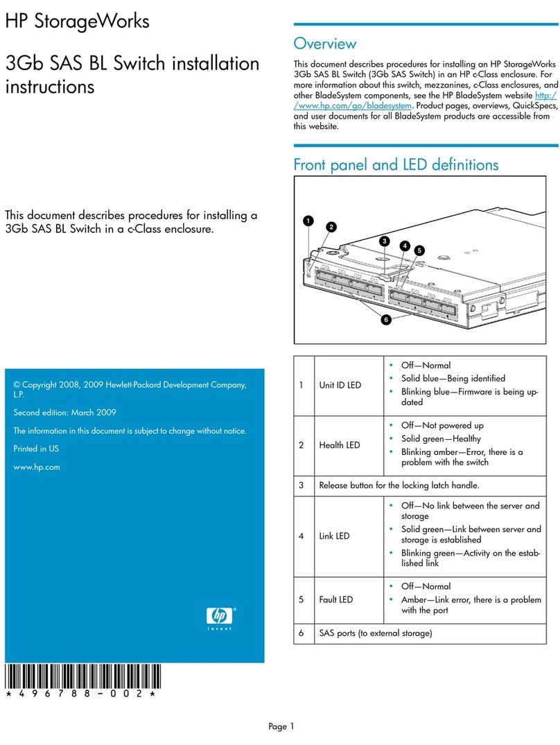
HP StorageWorks 9100 - Extreme Data Storage... installation instructions
Kramer
Kramer VP-773AMP user manual
Force 10
Force 10 S50 quick reference
