NORTHROP GRUMMAN NAVIGAT X MK 1 Manual

Northrop Grumman Sperry Marine B.V. (Representative Office)
Woltmanstr. 19 • D-20097 • Hamburg, Germany
Tel.: +49-40-299 00-0 • Fax: +49-40-299 00-146 • E-mail: service.de@sperry.ngc.com
Operation, Installation and Service Manual
NAVIGAT X MK 1
Digital Gyrocompass Systems
Type 4914-CA, Stock No. 74807 and Type 4914-CC, Stock No. 74811
056343/C, 08 May 2008

056343/C NAVIGAT X MK 1
© 2008 Northrop Grumman Sperry Marine B.V.
This document and the information herein is the intellectual property of Northrop Grumman
Sperry Marine B.V. [NGSM BV] and it’s associate companies and may not be copied or repro-
duced without the express permission of NGSM BV.
Specifications were correct at time of press but may be varied in accordance with NGSM BV’s
policy of continuous product development.
Any technical content should be verified with NGSM BV.
Sperry Marine, with worldwide headquarters in Charlottesville, VA, and major engineering and
support offices in Melville, NY, New Malden, England, and Hamburg, Germany, is part of the
Northrop Grumman Electronic Systems sector.
Revision Record
Rev. Date Remarks
C 08 May 2008 Added new options (AD10 output, alarm mute relay, speed filter).
B 17 Nov 2006 Removed gyrospere installation/service instructions. These are now
contained in separate documents delivered with the respective gyro-
sphere and container.
All information regarding the master PCB refers to the new PCB, stock
no. 20672.
A 18 Jan 2005 initial release.

NAVIGAT X MK 1 056343/C
i
Safety Instructions
Safety Notice Conventions
The following safety notice conventions are followed throughout this
manual:
DANGER
A Danger notice contains an operating or main-
tenance procedure, practice, condition, state-
ment, etc., which, if not strictly observed, will
result in injury or death of personnel.
WARNING
A Warning notice contains an operating or
maintenance procedure, practice, condition,
statement, etc., which, if not strictly observed,
could result in injury or death of personnel.
CAUTION
A Caution notice contains an operating or main-
tenance procedure, practice, condition, state-
ment, etc., which, if not strictly observed, could
result in damage to, or destruction of equip-
ment.
Note
A Note contains an essential operating or main-
tenance procedure, condition or statement,
which is considered important enough to be
highlighted.
Special safety symbols may be used in this
manual to indicate:
Risk of electrical shock.
Used in conjunction with a Danger or Warning
notice.
Electrical components sensitive to electrostatic
discharge.
Used in conjunction with a Caution notice.
056343/C NAVIGAT X MK 1
ii
General Safety Information for the Operator
WARNING
Never rely on one heading source alone to navigate a vessel.
Always confirm the plausibility of the NAVIGAT X MK 1 heading and the
speed and position input data against all available aids to navigation.
WARNING
After a power-up from cold, the NAVIGAT X MK 1 requires a settling time
of three hours before reliable heading data is available.
Power up the system at least three hours before leaving harbour.
Power down the system during long docking periods only.
Make sure that the NAVIGAT X MK 1 has settled before using its heading
as the reference for heading control systems, RADAR, ECDIS, etc.
A magnetic heading source should be made active only in case of failure
of the gyrocompass(es).
WARNING
Before using this system, operators must be appropriately trained and
familiar with the operating procedures and safety instructions contained
in this manual.
Keep system manuals in a well-known, readily available location.
CAUTION
The supporting fluid in the gyrosphere container will start freezing at
temperatures below 0 °C.
The NAVIGAT X MK 1 may no longer be operated when the ambient tem-
perature at the gyrocompass’ location falls below –10 °C while the com-
pass is in operation or when the ambient temperature falls below 0 °C
while the compass is not in operation.
CAUTION
Any service work on the gyrosphere is to be carried out by authorized
service personnel only.
CAUTION
Do not clean the compass housing with organic solvents, acetone or any
other substance which could damage or discolour plastic.
Use only soapy water or a mild detergent to clean the compass housing.

NAVIGAT X MK 1 056343/C
1-iii
General Safety Information for Service Personnel
DANGER
When the compass is energized, the gyrosphere operating voltage of
100 VAC @ 337 Hz is present on the master PCB, the gyrosphere supply
lines, and across the gyrosphere contacts.
When the AC main supply is switched on, live voltages are present at the
line filter and the power transformer’s terminals.
CAUTION
The gyrosphere is always to be transported in its carrying box in the orig-
inal transport container.
Do not throw or drop the transport container.
The transport container is to be transported in an upright position only.
Carry the carrying box containing the gyrosphere by hand only and han-
dle it with extreme care. Remove the gyroshpere from the carrying box
only if required for immediate installation.
CAUTION
After power-down of the compass system, it may take up to 45 minutes
for the gyroscopes to stop rotating.
During this time, the container must be handled with extreme care.
Should the sphere touch the wall of the container, the momentum of the
rotating gyroscopes will make it topple and damage the center pin.
CAUTION
The NAVIGAT X MK 1 contains electrostatic sensitive components.
Electrostatic discharge may permanently damage components.
When servicing the NAVIGAT X MK 1, take precautions to prevent elec-
trostatic discharge. Avoid touching any of the electronic circuitry.
CAUTION
It cannot be guaranteed that parameter settings in the User and Setup
menus and the entries made in the Magnetic Compass Calibration table
are left intact when the software is exchanged.
Before exchanging the system software IC, record all parameter settings
to be able to re-enter them manually, if required.

056343/C NAVIGAT X MK 1
1-iv

NAVIGAT X MK 1 056343/C
v
Contents
Safety Instructions
Safety Notice Conventions........................................................................... i
General Safety Information for the Operator ............................................ ii
General Safety Information for Service Personnel................................... iii
Chapter 1: Introduction
1.1 Design and Main Features........................................................................ 1-1
1.2 Operating Principle ................................................................................... 1-2
1.3 Example System Configurations ............................................................. 1-3
Standalone Gyrocompass/TMC System ................................................. 1-3
Dual NAVIGAT X MK 1 Gyrocompass/TMC System................................ 1-4
1.4 Technical Data............................................................................................ 1-5
Chapter 2: Operation
2.1 Operating Conditions ............................................................................... 2-1
2.2 Display and Operating Keys ..................................................................... 2-2
Control and Display Unit .......................................................................... 2-2
2.3 External control devices ........................................................................... 2-3
2.4 Power-up Sequence .................................................................................. 2-4
2.5 Selecting the active heading source ....................................................... 2-5
2.6 Adjusting the display brightness............................................................. 2-5
2.7 Optional Functions.................................................................................... 2-6
Muting Alarms Remotely.......................................................................... 2-6
Reversing the Heading Display (180° offset)........................................... 2-6
Resetting/Acknowledging a Central Watch Alarm .................................. 2-6
2.8 Operating Menu ........................................................................................ 2-7
Entering and Quitting the Main Menu..................................................... 2-7
Navigating the Menu ................................................................................ 2-7
Selecting Parameter Settings ................................................................... 2-8
Editing Parameter Values ......................................................................... 2-8
2.9 Selecting a Display Data Page ................................................................. 2-9
2.10 Manual Settings Menu ........................................................................... 2-10
Manual Settings – Overview .................................................................. 2-10
Manual Settings – Parameters ............................................................... 2-12
2.11 User Setup ............................................................................................... 2-16
User Setup – Overview ........................................................................... 2-16
User Setup – Parameters ........................................................................ 2-17

056343/C NAVIGAT X MK 1
vi
Chapter 3: Errors and Alarms
3.1 Alarm Indication ........................................................................................ 3-1
Audible Alarm Indication .......................................................................... 3-1
Visual Alarm Indication............................................................................. 3-1
3.2 Acknowledging Alarms/Muting the Audible Alarm............................... 3-2
Alarm Acknowledge ..................................................................................3-2
Alarm Mute ................................................................................................3-2
3.3 Error messages .......................................................................................... 3-3
3.4 Service Info Menu (Service Setup 2) ....................................................... 3-5
Service Setup 2 – Access Code ................................................................ 3-5
Service Setup 2 – Overview......................................................................3-6
Service Setup 2 – Parameters................................................................... 3-7
Chapter 4: Scheduled Maintenance
4.1 Maintenance by Shipboard Personnel .................................................... 4-1
4.2 Gyrosphere Maintenance Specifications ................................................ 4-1
18-Month Maintenance ............................................................................. 4-1
Five-Year Maintenance.............................................................................. 4-2
Chapter 5: Preventive Maintenance
5.1 Protecting the Gyrosphere from Low Temperatures..............................5-1
Removing the container from the compass housing ............................. 5-2
Parts, materials and tools required .......................................................... 5-2
Procedure ................................................................................................... 5-2
Re-installing the container in the compass housing .............................. 5-4
Parts, materials and tools required .......................................................... 5-4
Procedure ................................................................................................... 5-4
Power-up function test .............................................................................. 5-6
Procedure ................................................................................................... 5-6
Chapter 6: Installation
6.1 Mechanical Installation............................................................................. 6-1
Installing the Compass Housing .............................................................. 6-1
6.2 Electrical Installation................................................................................. 6-2
AC Supply Power Configuration .............................................................. 6-2
Wiring Up the System............................................................................... 6-2
6.3 Gyrosphere Installation ............................................................................ 6-3
6.4 Initial System Configuration .................................................................... 6-4
6.5 Alignment Error Correction ...................................................................... 6-6
Magnetic Compass Calibration ................................................................ 6-7

NAVIGAT X MK 1 056343/C
vii
Chapter 7: System Configuration
7.1 Configuration Menu (Service Setup 1).................................................... 7-1
Setup Access Code.................................................................................... 7-1
Service-Setup 1 – Overview ..................................................................... 7-2
Service Setup 1 – Parameters .................................................................. 7-6
7.2 Factory Settings Menu (Technical Pages) ............................................. 7-16
Setup Access Code.................................................................................. 7-16
Technical Pages – Overview ................................................................... 7-16
Technical Pages– Parameters ................................................................. 7-17
Chapter 8: Troubleshooting
8.1 Troubleshooting Instructions ................................................................... 8-1
8.2 Location of Parts on the Master PCB ...................................................... 8-2
Exchangeable Components...................................................................... 8-3
Connectors................................................................................................. 8-3
Test Resistor / Trimpots............................................................................. 8-4
Diagnostic LEDs......................................................................................... 8-4
Chapter 9: Corrective Maintenance
9.1 Exchanging the System Software ........................................................... 9-1
9.2 Replacing Socketed ICs ............................................................................ 9-2
Appendix
A Setup and Configuration Tables
B Drawings

056343/C NAVIGAT X MK 1
viii

NAVIGAT X MK 1 056343/C
Design and Main Features 1-1
Chapter 1: Introduction
1.1 Design and Main Features
The NAVIGAT X MK 1 is a microprocessor controlled marine gyrocom-
pass system with integrated automatic North speed error correction.
As a gyrocompass, the system complies with IMO resolutions A.424(IX)
and A.694(17) and with EN ISO 8728.
The HSC-version (stock no. 74811) with a specially selected gyrosphere
also complies with IMO resolution A.821(19).
The rate of turn output of the NAVIGAT X MK 1 complies with IMO reso-
lution A.526(13).
The NAVIGAT X MK 1 has been type approved by the German Federal
Maritime and Hydrographic Agency (BSH), in accordance with the
Marine Equipment Directive (MED) 96/98/EC, as modified by Directive
2002/75/EC.
The single unit design with a polyurethane hard foam housing allows
the gyrocompass to be installed on any bridge. If required, the operating
unit may be installed at a location remote from the compass or an addi-
tional remote operating unit may be used.
The unique method of supporting the gyrosphere by means of mere
buoyancy ensures North stabilisation during short power failures. E.g.,
after a three minute loss of power, no more than two degrees of devia-
tion may be expected. Once power has been restored, the gyrocompass
will return quickly to the correct heading. The combined effects of the
twin rotors and the liquid damping system virtually eliminate latitude
error.
Heading is measured as a 13-bit absolute value with a digital shaft
encoder. The high-speed follow-up system (follow-up speed up to
100°/s) ensures that accurate heading and rate of turn data is provided
under all operating conditions.
Integrated monitoring of the supply powers, gyroscope current and the
follow-up system ensure secure and trouble-free operation.

056343/C NAVIGAT X MK 1
1-2 Operating Principle
1.2 Operating Principle
The north-seeking element used in the NAVIGAT X MK 1 system is the
gyrosphere, a hermetically sealed unit with a funnel-shaped recess,
reaching from the outer skin down to its center.
Inside the gyrosphere, two mechanically linked gyroscopes are mounted
with their spin axes horizontal in a carrying frame. The gyroscopes are
allowed to turn around the vertical, but torsion bands effect a defined
rest position, while a mechanical linkage ensures that the resultant spin
vector of the gyros remains stationary relative to the gyrosphere. This
twin gyro arrangement eliminates intercardinal roll error. Once the
gyros have run up to speed, their resultant spin vector, and with it the
sphere, settles in the direction of true North.
Figure 1-1:
The gyrosphere
The top of the gyrosphere contains an annular damping trough, half
filled with a viscous fluid. The fluid damps azimuthal oscillations of the
gyroscope system. The oscillation period is tuned to the Schuler period
of 84.4 minutes, so that heading errors during horizontal acceleration
due to changes in speed and/or direction are prevented.
The gyrosphere floats in a supporting fluid inside the gyrosphere con-
tainer. Because the buoyancy of the sphere is a little greater than its
weight, a bearing cup at the bottom of the recess is pressed against the
centering pin and keeps the sphere exactly centered in the container.
In order to make the gyroscope system pendulous, that is, to provide the
gravity controlling moment, the gyrosphere is designed so that its cen-
tre of gravity lies slightly below the centre of bouyancy.
The gyroscopes are in fact squirrel-cage induction motors, which attain
a speed of nearly 20000 rpm at a voltage of 100 VAC @ 337 Hz.
In the Mod. 10/3 container, their supply power is applied through the
electrolytically conducting supporting fluid, via the top and bottom con-
tacts. In the Mod. 10/2 and Mod. 7/2 containers, the power is applied via
the centering pin and the bottom contacts.
A follow-up control circuit keeps the container aligned with the sphere at
all times, thus heading can be derived from the container’s orientation.
While systems with the Mod. 10/3 container employ an optical pickoff to
provide the follow-up control signal, systems with the Mod. 10/2 and
Mod. 7/2 containers use a resistance bridge circuit, formed by the con-
ducting paths from the contact pins in the container, through the sup-
porting fluid and to the equator contact of the gyrosphere.
centering pin
N gyro
gyro linkage
damping trough
S gyro
gyrosphere shell
NAVIGAT X MK 1 056343/C
Example System Configurations 1-3
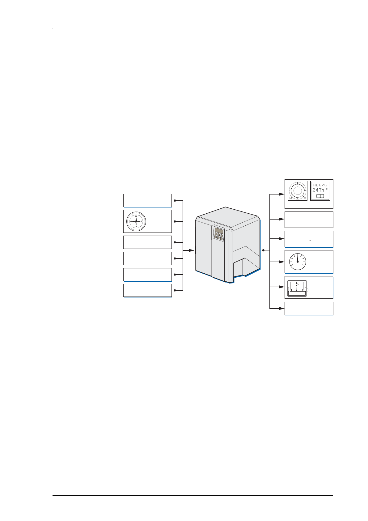
1.3 Example System Configurations
Standalone Gyrocompass/TMC System
As a standalone system, the NAVIGAT X MK 1 provides North-speed
error corrected true heading as well as rate of turn data.
If a fluxgate sensor, type 4863, or an electronic magnetic compass is
installed, the NAVIGAT X MK 1 applies magnetic variation and distrib-
utes magnetic heading data to external equipment (TMC function).
The heading diff. alarm function permits to monitor the difference
between the gyro and magnetic heading sources.
In case of failure of the gyrocompass, the magnetic heading source may
be activated to provide an emergency heading reference for repeaters
and other peripheral equipment.
Figure 1-2:
Standalone
Gyrocompass/TMC
system
Magnetic
Compass
Position Receiver
Speed Log
Rudder Angle
Feedback Unit(s)
Status Signals In
Ext. Gyrocompass
ROT
Serial Repeaters
Equipment using
serial input
Equipment using
6 step/ input
Analogue
R.o.T.
Indicators
Nav. Data
Printer
Status Signals Out

056343/C NAVIGAT X MK 1
1-4 Example System Configurations
Dual NAVIGAT X MK 1 Gyrocompass/TMC System
The system shown in Figure 1-3 below is the standard configuration for
a dual NAVIGAT X MK 1 gyrocompass system.
In addition to the two NAVIGAT X MK 1 compasses, this system com-
prises the NAVITWIN IV heading management system and the Switch-
Over Unit Type 4932.
By selecting the active heading source at the NAVITWIN IV, the operator
determines which compasses’ data is distributed via the Switch-Over
Unit to external equipment, such as heading control systems, RADAR,
compass repeaters etc.
The NAVITWIN’s heading diff. alarm function permits to monitor the dif-
ference between any two of the available heading sources.
The off heading alarm function permits to monitor the difference
between the actual heading from the active source and the set heading
order, as received from a heading control system or entered manually.
Alarms generated locally by a NAVIGAT gyrocompass are indicated and
may be acknowledged at the NAVITWIN IV.
In turn, the NAVITWIN IV transmits system-wide operational settings
and setup parameters to the NAVIGAT gyrocompasses.
The available heading sources, the current source selection and the hdg.
diff. threshold are also indicated at both gyrocompasses.
If a magnetic heading source is installed, the NAVITWIN applies mag-
netic variation and distributes the data to external equipment (TMC
function). In case of failure of the gyrocompasses, the magnetic heading
source may be activated to provide an emergency heading reference for
repeaters and other peripheral equipment.
Figure 1-3:
NAVIGAT Dual
Gyrocompass System
GYRO
1
GYRO
2
MAGN
COMP
246.8
246.7
247.0
G1 Hdg.
G2 Hdg.
M Hdg.
Source Sel.
Status
Alarm Status
(Hdg. Diff, Off Hdg)
G/ M Headings,
RoT, and all other
data/signals
distributed via
Switch-Over Unit
Switch-Over Unit
NAVITWIN IV
G2
M
G1
Note
A system with one NAVIGAT X MK 1 and one NAVIGAT 2100 fiber-optic
gyrocompass is also possible in an otherwise identical configuration.

NAVIGAT X MK 1 056343/C
Technical Data 1-5
1.4 Technical Data
Accuracies
heading:
lin. mean settle point error
static error
dynamic error
deviation after 3 min. power interruption
≤0.1° secant latitude
≤0.1° secant latitude
≤0.4° secant latitude
< 2°
rate of turn ≤0.5°/minute
Operational Characteristics
mean setting time < 3h
max. follow-up speed 100°/s
freedom of roll and pitch
- with container Mod. 10
- with container Mod. 7
±40°
±90°
MTBF 40 000 h
Environmental Requirements
ambient temperature, operation –10 to +55 °C
ambient temperature, storage
(without supporting fluid)
–25 to +70 °C
environmental conditions / EMC in accordance w. IEC 60945
Protection Grade
according to IEC 60529/DIN 40050 IP 23
Magnetic Clearance
to standard magnetic compass 0.6 m
to steering magnetic compass 0.4 m
reduced, to standard magnetic compass 0.3 m
reduced, to steering magnetic compass 0.3 m
Power Supply
supply voltage main: 115/230 VAC, 50/60 Hz;
backup: 24 VDC (18-36 V), includ-
ing automatic switchover to
backup supply in case of main
supply failure
max. ripple content DC supply ±4 Vpp; extreme values may not
exceed 36 V or fall below 18 V
power consumption:
start-up
operation
each repeater compass
AC: 125 VA; DC: 80 W
AC: 75 VA; DC: 45 W
7 W

056343/C NAVIGAT X MK 1
1-6 Techni cal D ata
Dimensions and Weight
width 404 mm
height 520 mm
depth 420 mm
weight 25 kg approx.
Data Inputs
ext. gyro heading NMEA 0183 / IEC 61162-1
or PLATH protocol
or Lehmkuhl (1200, 2400, 4800 or
9600 Bd.)
magnetic heading NMEA 0183 / IEC 61162-1
or PLATH protocol
or NAVIPILOT
position NMEA 0183 / IEC 61162-1
speed NMEA 0183 / IEC 61162-1
compass monitor NAVITWIN NMEA 0183 / IEC 61162-1
Signal and Status Inputs
magnetic heading,
fluxgate sensor
sin., cos. and ref. voltages from
Sperry Marine fluxgate sensor
type 4863
speed, 200 pulse/nm connection to P.Gnd via ext. con-
tact, momentary
rudder angle feedback unit
(2x; reads rudder angle for output
to NAVIPRINT)
0 – 5 VDC return voltage from
feedback potentiometer(s)
steering mode status (auto/man) connection to P.Gnd via ext. con-
tact, latching
ext. heading reference sel.
(gyro1/gyro2)
connection to P.Gnd via ext. con-
tact, latching
ext. heading reference sel.
(gyro/mag)
connection to P.Gnd via ext. con-
tact, latching
ext. alarm acknowledge (mute) connection to P.Gnd via ext. con-
tact, momentary
status input port (log status or
hdg. +180° function)
connection to P.Gnd via ext. con-
tact, latching
404
520
420420

NAVIGAT X MK 1 056343/C
Technical Data 1-7
Data Outputs
serial repeater outputs
(12x TTL)
NMEA 0183
sensor data outputs
(4x RS-422; 3 available if AD10
output active)
NMEA 0183 / IEC 61162-1
FAST output
(1x RS-422)
NMEA 0183 / IEC 61162-1
or PLATH protocol
SuperFAST output
(2x RS-422; 1 available if AD10
output active)
NMEA 0183 / IEC 61162-1
or NMEA 0183 / IEC 61162-2
or PLATH protocol
AD10 heading data output AD10 serial data and clock
NAVITWIN output NMEA 0183 / IEC 61162-1
to ext. gyro / compass monitor
NAVITWIN
NAVIPRINT output serial data to nav. data printer
Signal and Status Outputs
6 step/° output (2 x) 3 phases, switched to 0V potential
if active („minus switching“),
common positive;
internal supply 24 VDC
max. 18 W
(12–70 VDC phase voltage when
ext. power supply is used)
rate of turn, analogue ±0.1–999.9 mV/°/min;
max. 10 V, 10 mA
power failure/general alarm
heading difference alarm
max. ROT exceeded alarm,
heading source sel. status
status out to switch-over unit
watch alarm acknowledge
AC power status
DC power status
potential-free contact closures,
each rated
30 VDC/1.0 A,
100 VDC/0.3 A,
125 VAC/0.5 A

056343/C NAVIGAT X MK 1
1-8 Techni cal D ata

NAVIGAT X MK 1 056343/C
Operating Conditions 2-1
Chapter 2: Operation
2.1 Operating Conditions
The permitted ambient temperature for the operation of the gyrocom-
pass system is -10 – +55 °C.
When the ambient temperature at the gyrocompass’ location falls below
-10 °C while the compass is in operation or when the ambient tempera-
ture falls below 0 °C while the compass is not in operation, the gyro-
sphere container must be removed from the compass housing and
stored in a place where the ambient temperature will not fall below 0 °C.
If no storage place is available where the ambient temperature will not
fall below 0 °C, the gyrosphere must be removed from the gyrosphere
container to prevent possible damage by frozen supporting fluid.
CAUTION
The supporting fluid in the gyrosphere container will start freezing at
temperatures below 0 °C.
The NAVIGAT X MK 1 may no longer be operated when the ambient tem-
perature at the gyrocompass’ location falls below –10 °C while the com-
pass is in operation or when the ambient temperature falls below 0 °C
while the compass is not in operation.
CAUTION
The gyrosphere may be removed from the gyrosphere container by
authorized service personnel only.

056343/C NAVIGAT X MK 1
2-2 Display and Operating Keys
2.2 Display and Operating Keys
Control and Display Unit
Figure 2-1:
NAVIGAT X MK 1
control and display unit
Display
Operating Keys
➀LCD Display: 4x20 character text display
In normal operational mode, shows the available heading sources
and the heading diff. alarm threshold.
In menu mode: displays the currently active op. menu screen
➁MENU /F1 key: Calls up the main menu from normal operational
mode. When pressed in menu mode, returns to next higher menu
level.
When pressed simultaneously with the SHIFT key, the F1 function is
executed.
➂Up () / F2 key: In menu mode, returns from the main menu to nor-
mal operational mode. Within a sub-menu, scrolls up through avail-
able pages on same menu level.
When pressed simultaneously with the SHIFT key, the F2 function is
executed.
➃Down () / F3 key: Calls up the Main Menu from normal operational
mode. Within a sub-menu, scrolls down through available pages on
same menu level.
When pressed simultaneously with the SHIFT key, the F3 function is
executed.
➄SHIFT key: Pressed with other key to call up key’s SHIFT function.
➅DIM+ / RESET key: Adjust the display brightness.
When pressed simultaneously with the SHIFT key, the RESET function
is executed.
➆DIM- / ENTER key: Adjust the display brightness.
When pressed simultaneously with the SHIFT key, the ENTER func-
tion is executed.
5
1
2
3
6
4
7
Table of contents
Popular Boating Equipment manuals by other brands


Seamax
Seamax Sunlitec manual

JRC
JRC Fleet F77 Operation manual

Lippert
Lippert Taylor Made EasyGuide 2022106874 Installation and owner's manual

Raymarine
Raymarine Dragonfly-4 DV Installation and operation instructions

SLEIPNER MOTOR AS
SLEIPNER MOTOR AS Side-Power Series installation manual

DockCraft
DockCraft DockSider DS200 Assembly, Installation, Setup, and Operating Instruction


