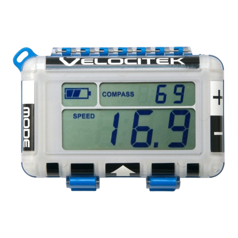
Velocitek Prostart User manual

Made by Velocitek in San Mateo, California
Firmware Version v2.0
Revision Date July 21, 2020

Contents
INTRODUCTION 4
FEATURES 5
INSTALLATION 6
BATTERIES 8
BATTERY LIFE 8
RECHARGING THE BATTERY 8
BUTTONS 9
ICONS 10
MODES 10
START MODE 11
TIMER 11
DISTANCE TO LINE 11
START LINE PACING GUIDES 11
RACE MODE 12
SPEED 12
MAGNETIC HEADING 13
COURSE OVER GROUND 13
HEEL ANGLE BAR GRAPH 14
OPERATION 15
POWER ON AND OFF 15

ACQUIRE A GPS SIGNAL 15
USING THE BACKLIGHT 16
SHOW OFF YOUR MAXIMUM SPEEDS 16
KEEP YOUR HAND ON THE TILLER 17
SET THE START LINE 18
USE THE TIMER 19
CONFIGURATION 20
CONFIGURING YOUR PROSTART 20
SETTING COMPASS DECLINATION AND BOW OFFSET 21
SETTING DIRECTION OUTPUT AND COMPASS DAMPING 22
MAGNETIC DECLINATION 23
THREE RESOURCES FOR FINDING YOUR LOCAL MAGNETIC DECLINATION: 23
BOW OFFSET 23
HEADING /COG 23
COMPASS DAMPING 23
UNDERSTANDING ‘DISTANCE TO LINE’ 25
PINGING WITHOUT THE BOW OFFSET 25
PINGING WITH THE BOW OFFSET 25
SETTING THE ENDS 26
HOW TO USE TIME AND DISTANCE 26
UNDERSTANDING ‘LINE SQUARE TO’ 27
RECALLING ‘LINE SQUARE TO’ERROR!BOOKMARK NOT DEFINED.
DATA STORAGE 28
DOWNLOAD DATA 28
SOFTWARE 28
VELOCITEK CONTROL CENTER 28
REPLAYS 28
FIRMWARE 28

Introduction 4
Introduction
The new ProStart is the distillation of more than a decade of experience and customer feedback building
stand-alone, GPS-based, distance-to-line starting aids. It’s all about time and distance.
Now, the best distance-to-line tool ever just got better. The new ProStart has the same great user
experience you know and love and now features crystal-clear optics, zero-latency navigation, and
multicolor backlight.
Made by Velocitek in San Mateo, California.

Features 5
Features
Only essential features used by professional sailors are included in the product.
High-contrast LCD bonded to Gorilla® Glass anti-reflective / anti-glare lens
4 Hz screen update rate (4 times per second)
Red and white LED backlight
72 channel, 18Hz multi-constellation GPS receiver
100 Hz solid-state 6-axis inertial measurement unit (IMU)
High-precision 3-axis geomagnetic sensor (compass)
100 hour Lithium-ion battery
GPS Speed, magnetic compass, and distance to line updated four times a second
Countdown start timer
Maximum and best 10 second average speed recall
Over 1000 hours of data storage at a 4 Hz (4 times per second)
Data download through USB link
User configurable magnetic declination
Line Square To
Heel angle
Waterproof (IPX8) to 3m
Two year warranty

Installation 6
Installation
The ProStart comes with a cradle that interlocks with it. Install the cradle permanently on your boat.
Press the tab on the cradle to unlock the ProStart from it.
The ProStart Cradle works with M4 Metric flat head countersunk machine screws. Alternatively, you can
use Imperial No. 6 flat head countersunk machine screws in place of M4 fasteners. Always use Marine
Grade fasteners when mounting the ProStart Cradle and/or Mounting Brackets.

Installation 7
Do not use rounded head screws with the ProStart cradle. Non-countersunk screw heads will interfere
with mounting the ProStart in its cradle.
The ProStart now features a magnetic compass. If you intend to use the magnetic compass feature,
mount the back of the cradle perpendicular to the centerline of the boat. The cradle should be installed
at least 1.0m away from steel, iron, other ferromagnetic metals and permanent magnets.
If you only intend to use the GPS features of the ProStart, the cradle can be installed anywhere on the
boat with a view of the sky.
For instructions on changing the ProStart from magnetic compass to course over ground, see the
Configuration section on page 20.
Several mounting options are available for the ProStart. For details, go to
https://www.velocitek.com/collections/accessories.

Batteries 8
Batteries
The ProStart is powered by an onboard Lithium Polymer battery.
Battery life
The battery indicator is located on the bottom of the LCD screen. When the battery is fully charged, the
device will last 100 hours in normal operation with the white or red backlight on. From a full charge with
the backlight off, the ProStart will run for 200 hours with no additional charge. When the battery is
empty the device will go into low battery mode and flash the battery outline.
When the battery is exhausted, connect the ProStart to a USB port or a phone charger using the supplied
cable. From low battery the ProStart takes approximately 11 hours to charge completely using a 5 volt, 1
amp wall adapter (iPhone or similar) or 55 hours to charge completely via a USB port on a computer.
Recharging the Battery
To recharge the battery, connect the ProStart to a USB port or a phone charger using the supplied Micro
USB cable. The ProStart uses a standard Micro USB cable.
While the ProStart is charging the LCD will display “>USb”, the USB trident logo will be visible at the
bottom of the LCD screen and the battery icon will show the charging progress (see illustration below).
When the battery is completely charged the cycling animation will stop and the battery will show full
with both bars showing.
Full Battery
Half Full
Low Battery
Low battery
< ½ full - One
bar flashing
> ½ full - One
bar solid, one
bar flashing
Full battery -
both bars solid
Full charge.
Go sailing!

Buttons 9
Buttons
There are a total of eight buttons on the ProStart as illustrated above. The buttons will be referred to
in capitalized blue text throughout this document as follows, PWR,MODE,MAX,RESET,+1,PIN,RC and
GUN.
Pin
Sets current
location as
pin end of
start line
Mode
Max Speed
On/Off
Timer Reset
Timer +1
Gun
Timer Start/Sync
Race Committee
Sets current
location as
boat end of
start line

Icons 10
Icons
Modes
The ProStart has two modes: Start Mode and Race Mode. Each mode provides you with the essential
information at different stages of the race, before and after the gun.
The mode indicator can be found at the upper left hand corner of the LCD screen.
Start Mode: time & distance
Race Mode: speed & heading
Speed
Heading
Timer
Distance
Max
Speed
Best 10
Sec.
Speed
USB
Battery
GPS
Available

Modes 11
Start Mode
Start mode combines a timer and perpendicular distance to line display to provide the information
necessary for a perfect start at the gun.
The semi-circles next to the PIN and RC buttons indicate if the respective ends are set. When both ends
are set a line appears between them to illustrate that the line is set.
Timer
The count-down timer displayed as mm:ss. The time can be set from 1:00 to 15:00.
Distance To Line
‘Distance To Line’is the perpendicular distance to the user defined line. Refer to Set Start Line on page
18 for detailed information on setting the start line. ‘Distance To Line’ is displayed in meters. A negative
‘Distance To Line’ means that the boat is over the line. Three hyphens ‘---’ are displayed when the line is
not defined and a GPS signal is available. When the ‘Distance To Line’ is larger than 1000 meters ‘>999’ is
displayed.
Start line pacing guides
In the final minute of the countdown the bar graph segments will display ‘Pacing Guides,’ giving you an
indication of whether you are on track to be early or late to the line given your current boat speed and
heading. Below is a description of how this algorithm works so that you can employ this feature in your
starts with confidence.
Line is Set
Start Mode
Indicator
Distance-
to-line
Display
Indicator
Timer
Display
Indicator
Line End
Set
Indicator
Distance
Timer

Modes 12
The early / late bar graph provides a graphical representation for your estimated location at the gun
based on your current position, speed, Course Over Ground, and the time remaining in the countdown.
The bar graph extends above the illustrated line if the calculated future location is over the line and
below the illustrated line if your future location is under the line. When no bar graph segments are
showing - the “0” display - your estimated future location at the gun is between the line and 2 meters
below the line. Each segment shown represents +/- 2m from this “0" location. For example, 2 bar graph
segments showing above the line represents that you are predicted to be between 2m and 4m over the
line at go. For simplicity’s sake this algorithm assumes the line to be of infinite length so it does not
compensate for any situation where your current heading would not take you through the starting line.
The goal is to eliminate all the bar segments around the perimeter and only have the semicircles
showing. This indicates that at your current speed and heading you are expected to be within 2 meters
of the line at the gun.
Race Mode
Race mode displays information crucial during the race: speed, magnetic heading or COG, and heel
angle.
Speed
Speed is calculated by the GPS unit by measuring the Doppler shift in GPS signals. It is displayed in Knots
(Nautical Miles per Hour).
Heading / COG
Speed
Race Mode
Indicator
Speed
Display
Indicator
Heading
Display
Indicator

Modes 13
Magnetic Heading
With the addition of a solid-state geomagnetic (compass) sensor, the ProStart’s factory default direction
output is magnetic heading. The default heading is magnetic heading of the device expressed in degrees
with 360˚ being North.
When the ProStart’s direction output is set to magnetic heading, the ProStart’s top line will show
compass heading with three digits at all times. Leading zeros will be displayed when the heading is not
three digits, i.e. eleven degrees will be shown as 011° and three degrees will be shown as 003°.
See the Configuration section on page 20 for instructions on changing the ProStart’s direction output
from magnetic compass to course over ground.
Course Over Ground
The user has the option to substitute Course Over Ground (COG) in place of Heading. COG is calculated
by the GPS unit by measuring the Doppler shift in GPS signals.
Either true or magnetic COG can be displayed by entering your local magnetic declination into the
ProStart. “True COG” is referenced to true north. “Magnetic COG” is referenced to the local magnetic
north. When using a magnetic compass in conjunction with the ProStart, displaying COG in degrees
magnetic can be useful since both measurements will be referencing magnetic north.
By default, COG is displayed in degrees true. To display COG in degrees magnetic the local magnetic
declination must be entered in the device settings. See the Configuration section on page 20 for
instructions on entering your local magnetic declination into the ProStart.
The ProStart displays COG only when your speed is greater than 0.5 knots. If your speed is less than 0.5
knots the ProStart will display ‘- - -’ for COG regardless of which direction you are moving.
Unlike the magnetic heading from a compass, COG requires movement. COG depends only on the
direction you are moving, not the direction the device is pointing. If your ProStart is configured to display
COG, the ProStart will give you accurate COG information regardless of the orientation in which it is
mounted on your boat (i.e. mounted on the sides of a boom, or a tacking bracket on a Moth).
When the ProStart’s direction output is set to COG, the ProStart’s top line will show COG with no leading
zeros, i.e. eleven degrees will be shown as 11° and three degrees will be shown as 3°.

Modes 14
Heel Angle Bar Graph
In Race Mode, with magnetic heading selected as the direction output, the ProStart detects the heel
angle of the vessel allowing the sailor to balance the power and keep the boat on her lines. Each bar
segment represents 2.5° of heel.
To zero out the heel angle, press RESET when the ProStart is in Race Mode.
When COG is selected as the direction output, the heel angle feature is disabled.
Heel angle is also recorded in the ProStart’s data storage. Heel to starboard is shown as positive degrees.
Heel to port is shown as negative degrees.
Each segment represents 2.5°of heel
-12.5°
12.5°
0°

Operation 15
Operation
Power On and Off
Press the POWER / LIGHT button (top-center) to turn on your ProStart.
Press and hold POWER / LIGHT for three seconds to shut down your ProStart.
Acquire a GPS Signal
The operation of the ProStart relies on low-power radio signals from GPS satellites that orbit the earth at
an altitude of approximately 20,000 km. As a result, the ProStart must be outdoors with a clear view of
the sky to function properly. Stay away from tall buildings and forests when acquiring a signal off the
water since these obstacles block or reflect the signals making it difficult to obtain signal.
GPS Found
GPS Lost
Searching for GPS signal
Searching indicator is displayed
at the bottom and bar segments
travel around the circumference
of the LCD.
GPS Signal Acquired
GPS Search
GPS Acquired

Operation 16
When the ProStart is first turned on, it must download information from GPS satellites before it can
acquire a GPS signal.
The satellite acquisition process can take up to 5 minutes.
Using the Backlight
The ProStart features a white or red LED backlight.
With the ProStart powered on, press POWER / LIGHT to cycle the backlight between white, off, and red.
If your ProStart has a low battery, the backlight will automatically turn off to reduce power consumption
and extend the runtime of your ProStart.
Show Off Your Maximum Speeds
Everyone likes to know how fast you went. The ProStart max speed recall pulls your best speeds up with
the click of a button.
Display both your instantaneous and 10 second average maximum speed by holding MAX. The maximum
speeds are stored in non-volatile flash memory and are stored until overwritten with higher speeds or
the user resets the maximum speeds.
The ProStart’s max speed Instantaneous Max is a two second average and the Ten Second Average Max
is self-explanatory. These max speeds are calculated from Doppler speeds.
The maximum speeds are not limited by track storage capacity.
Press RESET while max speeds are
displayed to reset the max speeds
Maximum 10
second Average
Speed
Maximum
Instantaneous
Speed
Hold MAX to display max speeds

Operation 17
To reset the maximum speeds, press RESET while holding MAX.
Keep Your Hand on the Tiller
Modes switch automatically to minimize the need for your input. The mode switches from Start to Race
mode when the timer expires. The mode switches from Race to Start mode when any of the start related
buttons, RC, PIN, GUN, RESET and +1, are pressed.
when timer expires
when RC, PIN, GUN, RESET, +1 is pressed

Operation 18
Set the Start Line
Race Committee Set
Pin Set
Set the right end by pressing RC.
The set end is indicated by a semi-circle next to
RC in the illustration.
When an end is set, an indicator will flash for 3
seconds at the bottom of the LCD at the
respective ends.
Set the start line pin and race committee ends
by pressing PIN and RC respectively.
The semi-circles next to PIN and RC indicate if
the respective ends are set. The semi-circles
flash when the end is not set and go solid
when set.
The ends can be set in either order.
The ends can be set again by pressing PIN or
RC.
Press both PIN and RC simultaneously to clear
the ends.
Perpendicular distance-to-line is displayed
numerically, in Meters.
Line Square To
Start Line Set
Distance to Line
No Ends Set
Once the start line is set, the ProStart will
display a line between the semi-circles to
indicate that the line is set.
The direction to which the start line is square
will flash three times (° magnetic). See
understanding ‘Line Square To’ section on
page 27 for more information.

Operation 19
Use the Timer
+1 min
+1 min
Sync Timer
Timer Expired
Timer Counting Down
Add one minute to the timer without
stopping the timer by pressing +1.
Reset timer by pressing RESET.
Sync timer by pressing GUN. The
timer will round down to the nearest
minute, 4:00 in this case.
RESET Timer
Start Timer
Timer Reset
Change the reset time by pressing +1
to scroll through the minutes. The
timer can be set to 1:00 ~ 15:00.
Start the timer by pressing GUN.
Post Timer Expired
The timer will display the ‘Distance
to Line’ at 0:00 for 10 seconds after
the timer expires.
After the 10 seconds, the display will
switch automatically to race mode.
Other manuals for Prostart
2
Table of contents
Other Velocitek Boating Equipment manuals
Popular Boating Equipment manuals by other brands

Garelick
Garelick 19250 installation instructions

Quick
Quick ARIES user manual

Rave Sports
Rave Sports Mambo owner's manual

MINN KOTA
MINN KOTA RAPTOR installation instructions

Ideal Windlass
Ideal Windlass CWM Installation, operation & maintenance instructions

Quick
Quick mc2X 25k Installation and use manual

Uflex
Uflex Velair i10 VSD SMART Installation and user manual

Sea Eagle
Sea Eagle NeedleNose SUP 116 instructions

Dynamic Dollies & Racks
Dynamic Dollies & Racks UFO Assembly instructions

Legend
Legend DUV 31 TRAILER install guide

Seastar Solutions
Seastar Solutions i7700 installation manual

Hobie
Hobie Mirage Adventure Island owner's manual