Offshore 3345 NMEA2000 User manual

Revision 1.0
NMEA2000® MULTIFUNCTION DISPLAY
Part Numbers: 3345
USER MANUAL
3345


1 of 30
Contents
1 Introduction ...................................................3
1.1 Firmware Revision ........................................ 3
1.2 Product Features ..........................................3
2 Installation .....................................................4
2.1 Unpacking the box.........................................4
2.2 Mounting the unit .........................................4
2.3 Connecting the NMEA2000 Interface Cable ......4
3 Display Screens ...............................................5
3.1 Screen / Keypad Brightness Control .................5
3.2 Tank Display .................................................5
3.3 Battery / DC Source Supply ............................ 7
3.4 Generator / AC Source Supply .........................8
4 Conguration...................................................9
4.1 Cong Menu .................................................9
4.2 PIN Entry .....................................................10
4.2.1 Settings Menu ............................................11
4.2.2 Tank Setup ................................................11
4.2.2.1 Tank Name Setup .....................................12
4.2.2.2 Tank Volume Calibrate .............................13
4.2.2.3 Fluid Units Setup .............................. ......14
4.2.2.4 Tank Alarm Setup ....................................14

2 of 30
4.2.2.5 Percent Only Display ...............................15
4.2.3 Battery Setup ............................................15
4.2.3.1 Battery Name Setup .................................15
4.2.3.2 Battery Cong Setup ................................17
4.2.3.3 Battery Alarm Setup ................................17
4.2.4 External Control Setup ...............................18
4.2.5 AC Setup ...................................................19
4.2.5.1 AC Source Name Setup .............................19
4.2.5.2 AC Custom Setup .....................................21
4.2.6 Sys & Dev Instances ....................................21
4.2.7 Cong PIN Setup ........................................22
4.3 Com Viewer .................................................23
4.4 Demo On/Off Toggle ......................................23
4.5 About ..........................................................24
5 Maintenance ...................................................25
6 Technical Specication .................................... 26
7 Technical Support ........................................... 28
8 Warranty ........................................................29
9 Troubleshooting/FAQ ....................................... 30

INTRODUCTION
1
3 of 30
The Offshore System’s NMEA2000® 3345 MultiFunction Display is designed to monitor and
display information about the vessel’s tanks, DC supplies such as battery banks, Wind
Generators or Photovoltaic panels and AC Supplies such as generators, shore power or AC
busses.
This unit is designed to operate in a protected marine environment such as at the helm, chart
table or an engine room. It is very important that it is installed and set up correctly according
to this manual. Please read and follow the installation and setup instructions carefully to
achieve the best results.
The information in this manual corresponds to rmware v3.0
1.2 PRODUCT FEATURES
The NMEA2000® 3345 MultiFunction Display has the following features:
● Full Colour Sunlight Readable QVGA Display
● Pages displaying Tank, DC and AC source information
● User Selectable high and low level alarm limits
● User Selectable Display Units
● PIN protected setup and conguration
● NMEA2000 Interface

INSTALLATION
2
4 of 30
2.1 UNPACKING THE BOXx
You should nd the following items in the 3345 shipping box:
1 x 3345 NMEA2000® 3345 MultiFunction Display
1 x 3345 NMEA2000® Interface Cable
1 x Bag containing 4 mounting studs and thumbwheel nuts
1 x 3345 User Manual (This document)
2.2 MOUNTING THE UNIT
The unit should be mounted to a at surface by the 4 mounting studs and thumbwheel nuts.
Use the following unit drawing to identify the positioning of the central clearance hole and the
4 mounting stud locations.
2.3 CONNECTING THE NMEA2000 INTERFACE CABLE
The NMEA2000 interface cable rectangular plug should be plugged into the rear of the unit
taking care to observe the orientation pips on the plug match the corresponding recesses on
the unit’s socket. The other end of the cable should be connected to a nearby NMEA2000 Tee
connector (part number 3802). The male end of the cable should be inserted into the female
Tee connection noting the position of the keyway in the plug and the socket. Ensure that the
locking ring is securely tightened so that the connection remains waterproof and sound.
84.8 mm
51.3 mm
69.8 mm
69.8 mm
SECONDARY CONNECTOR
MATES WITH DT04-12PB
PRIMARY CONNECTOR
MATES WITH DT04-12PA

DISPLAY SCREENS
3
5 of 30
When the unit powers on it displays the initial product identity screen for a few seconds and
then displays the Tank Display.
3.1 SCREEN / KEYPAD BRIGHTNESS CONTROL
The unit has ve tactile buttons along its lower face and pressing any of the rst four buttons
will bring up the button bar which identies the current button function. Pressing the required
button will then execute the function chosen and the button bar will disappear a few seconds
later leaving the whole screen displaying the required data.
The fth button allows the user to vary the screen brightness and keyboard illumination which
is shown below.
Pressing the rst two buttons varies the screen brightness and the next two buttons vary the
key backlights. When the desired levels have been set press the fth button to clear the display
brightness control.
3.2 TANK DISPLAY
The rst display screen is Page 0 of the tank levels / volumes display and this can always be
selected by pressing the rst or most left hand button on the unit.
An example of this display is shown on the next page.

6 of 30
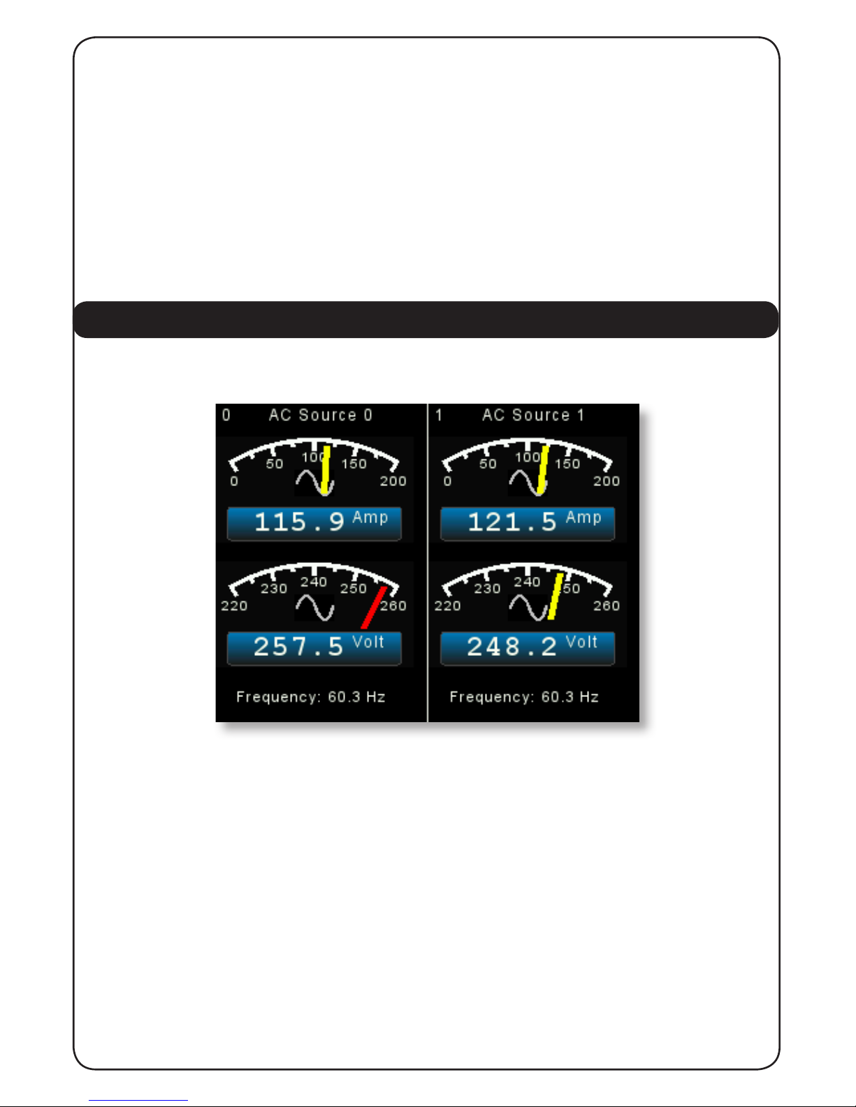
Here we can see that the Tank Display screen is split into 4 quadrants so the user can monitor
4 tanks at once. The centre of the screen at the junction of the four quadrants displays the
Quadrant Page Number which in the above case is Page 0. The display has eight different pages
available which are selected by repeatedly pressing the “TANK” button which will progressively
step through each display page. This allows the user to display up to eight pages each of four
tanks to a total of thirty two tanks.
Each quadrant of the above display contains the following information:
1. In the top centre of the quadrant is the user assignable tank name. When the
unit is delivered each tank type has a generic tank type name that can be set to
any name the user wishes to help identify the tank. See section 4.2.3 later in this
manual for information on how to do this.
2. At the top left hand side of the quadrant is the Tank Number or Instance which
needs to correspond with the number set on the tank sender Address or Instance
switch.
3. At the top right hand side of the quadrant (not shown above) there may be a
small alarm bell symbol which indicates that this tank level is outside it’s
alarm level limits and the alarm has been notied and acknowledged by the user.
See the section on Tank Level Alarms in section 4.2.6
4. In the centre of the quadrant is a gauge showing the tank level / volume per
centage and a pictogram of the tank type.
5. In the lower part of the quadrant is a digital display panel. This panel will show
the tank level as a percentage, ie 45%, if the total tank volume is not being trans
mitted by the sender. If the sender is transmitting the total tank volume as well as
the tank level then the digital display panel will show the remaining uid
volume in either Litres, US Gallons or Imperial Gallons as chosen by the
user conguration in section 4.2.2 below.
6. The gauge arc will display partially in red (not shown) if either the low or high
level alarm has been set to a suitable value and the alarm has been enabled. See
section 4.2.6 later in this manual for information on how to do this.
The user can select which tanks are displayed on each quadrant of each Quadrant Page by
pressing the “TANK” button to bring up the button bar then pressing the “RIGHT ARROW”
button which will alter the buttons to allow each quadrant to be changed.

7 of 30
Pressing the rst button the top left hand quadrant will change to display each of the different
tank sender levels being received and then a blank page in case the user does not wish to
display any tank in a given quadrant. Then by pressing the “BACK ARROW” button that selection
will be remembered and the display will revert to the normal tank display.
This can be repeated for each quadrant on each Quadrant Page giving the user the opportunity
to tailor the tank displays exactly as they wish.
3.3 BATTERY / DC SOURCE SUPPLY
By pressing the “BATT” button the display will show information about the rst two battery or
DC sources as shown below.
Repeated pressing of the “BATT” button will display the next two batteries or DC sources to a
total of 16 sources. Each side of the display contains the following information:
1. In the top centre of each side is the Battery or DC Source user assignable name. When the

8 of 30
unit is delivered each battery or DC source has a generic name that can be set to any
name the user wishes to help identify the Battery or DC source. See section 4.2.4 later in
this manual for information on how to do this.
2. At the top left hand side of each side there is a Battery or DC Source Instance number
which needs to correspond with the Instance of the DC Monitor supplying the data to the
network.
3. The top display gauge is the current charging or being drawn from the battery / DC
source. This gauge scale has our “Autoranging” feature so that if the current exceeds 60
amps the gauge scales will automatically autorange to a higher scale. This gauge also
includes a digital display panel showing the current ow numerically.
4. The second display gauge shows the voltage of the battery or DC source, also with
autoranging between 12 and 24 volt systems and a digital display panel.
5. At the bottom of each side is a battery temperature gauge.
3.4 GENERATOR / AC SOURCE SUPPLY
By pressing the “ACPWR” button the display will show information about the rst two AC
Generators or AC Busses or Shore Power as shown below.
Repeated pressing of the “ACPWR” button will display the next two AC sources to a total of 16
sources.
Each side of the display contains the following information:
1. In the top centre of each side is the AC Source user assignable name. When the unit is
delivered each AC source has a generic name that can be set to any name the user wishes
to help identify the AC source. See section 4.2.5 later in this manual for information on
how to do this.
2. At the top left hand side of each side there is an AC Source Instance
number which needs to correspond with the Instance of the AC Monitor supplying the data
to the network.
3. The top display gauge is the current being drawn from the AC source. This gauge also
includes a digital display panel showing the current ow numerically.
4. The second display gauge shows the voltage of the AC source, also with autoranging
between 110 and 240 volt systems, and a digital display panel.
5. At the bottom of each side is an AC Source frequency gauge.

CONFIGURATION
4
9 of 30
There are a number of congurable settings on the 3345 to allow the user to congure the unit
to most closely match their requirements. These are accessed by pressing and holding the right
hand button for at least 5 seconds which will start the Cong Menu.
4.1 CONFIG MENU
On this menu use the up and down arrow keys to change the yellow highlight to the action
required and then press “ENTER”
This menu allows you to do four things:
1. To go into the PIN protected settings menu to change the unit’s settings.
2. To look at the communications trafc. (This is an engineering function not normally
used).
3. To ip the unit in and out of Demo mode.
4. To display the about screen to check on version levels and serial numbers etc.
The use of these options is described on the next page.

10 of 30
4.2 PIN ENTRY
By moving the yellow highlight to “SETTINGS (PIN Reqd)” and pressing enter the display will
show the “CONFIG PIN ENTRY” screen to allow the user to enter a security PIN to access the
conguration screens. This is designed to ensure that only authorised persons can make changes
in this area.
By using the Up and Down and Right arrow buttons the user selected PIN can be entered and
the “ENTER” key will go to the “SETTINGS MENU” if the PIN is correct. If the PIN is not correct
the user is offered the choice to re-enter the PIN or exit back to the “CONFIG MENU” detailed
in 3.1 above.
The system is shipped with a PIN of 0000 and this can be reset to the user’s choice from the
“SETTINGS MENU” “CONFIG PIN SETUP”.

11 of 30
4.2.1 SETTINGS MENU
The “SETTINGS MENU” offers multiple options as shown below
Note the small arrow on the left hand screen indicates that there are more options than can
be shown on one page. All these options and the ones not shown are accessed by moving the
yellow highlighter to the chosen option and then pressing “ENTER”
4.2.2 TANK SETUP

12 of 30
4.2.2.1 TANK NAME SETUP
This screen is used to assign a 16 character name to each tank to identify the tanks more easily
on the tank display pages as can be seen on the following screen.
Firstly the user must select the tank type that is being named by pressing the “TANK TYPE”
button. This will cycle around all the available tank types and the display must be left on the
type of tank to be named.
Secondly, by pressing the “UP” arrow and “DOWN” arrow buttons select the tank instance or
tank number to be named then press “ENTER”.
Next use the “UP” and “DOWN” arrow keys to change the rst character of the name then
press the right key to move to be able to change the next character and so on. Please note that
the characters will cycle through A to Z upper case then a to z lower case, then a blank then
numbers from 0 to 9.

13 of 30
4.2.2.2 TANK VOLUME CALIBRATE
This screen is used to set the volume calibration table inside an Offshore System’s 3271 or 3281
Tank Level Sender.
The rst screen allows the user to choose the tank type and tank instance of the sender to be
calibrated.
When these have been chosen press “ENTER” to go to the next screen.
The user then enters the volume of uid at each desired level starting at the lowest chosen
point in as many or as few steps to 100%.
Note that this screen is re-presented at each step until the nal level of 100% is entered. When
this happens the unit calculates all the intermediate levels and stores that information in the
chosen sender.

14 of 30
4.2.2.3 FLUID UNITS SETUP
This screen is used to choose between displaying the Fluid Units in Litres, US Gallons or
Imperial Gallons as can be seen by the following screen.
The user can change the units by using the “UP” and “DOWN” arrows and pressing “ENTER” to
select their units of choice. Pressing “EXIT” will return to the “SETTINGS MENU”
4.2.2.4 TANK ALARM SETUP
This screen is used to set the Tank Level Alarm settings for each tank.
The user can select both low and high level alarms for each tank and the alarm level for each
type of alarm.
By pressing the “UP” and “DOWN” arrows the value in the highlighted line will change.
By pressing the “RIGHT” arrow the selector will highlight the Tank Type, Tank Instance, Alarm

15 of 30
Type Status and Alarm level for each alarm type. When the selected alarms have been set press
the “ENTER” key to store them and then the “EXIT” key to return to the settings menu.
4.2.2.5 PERCENT ONLY DISPLAY ON/OFF
This is a toggle menu item which will always show the uid level numeric value in percent
rather than amount.
4.2.3 BATTERY SETUP
4.2.3.1 BATTERY NAME SETUP
This screen is used to assign a 16 character name to each battery to identify the battery more
easily on the battery display pages as can be seen on the following screen.

16 of 30
Firstly, by pressing the up arrow and down arrow buttons select the battery instance or battery
number to be named then press “ENTER”.
Next use the “UP” and “DOWN” arrow keys to change the rst character of the name then
press the right key to move to be able to change the next character and so on. Please note that
the characters will cycle through A to Z upper case then a to z lower case, then a blank then
numbers from 0 to 9.
When the desired name has been written press “ENTER” then “EXIT” to store that name.

17 of 30
4.2.3.2 BATTERY CONFIG SETUP
This screen allows you to select an Offshore Systems DC monitor by instance and change its
properties. First select the instance using the “UP” & “DOWN” arrows on the left (if the battery
instances have been given names this will also show up) then press enter to select. A new right
arrow button will appear once the instance has been selected. To change the values you use
the “UP” & “DOWN” arrows and to proceed to the next eld you use the “RIGHT” arrow. Press
the ‘”ENTER” button at anytime to save the conguration.
4.2.3.3 BATTERY ALARM SETUP
To set an alarm rstly select the instance using the up/down buttons on the left (if the battery
instances have been given names this will also show up) then press enter to select. The rst
eld enables or disables the alarm. The next two elds are low/high voltage alarm values. When
the 3345 Multi function display detects a voltage under the low voltage value or higher than the
high voltage an alarm is displayed. The last temperature eld will show an alarm if the display
detects a temperature higher than the set threshold. The setup can be cancelled at any time
using the exit button on the far right.
Please see next page.

18 of 30
4.2.4 EXTERNAL CONTROL SETUP
This screen is used to set up the conditions to operate the 3478 Relay Output Module so that it
can control external alarms, external pumps and other relay controlled actions.
Firstly the user needs to select the Device Instance of the 3478 by using the following screen.
When the Device Instance has been chosen pressing “ENTER” will go to the next screen to allow
choice of the actions to operate each of the eight relays in the 3478 unit.
Table of contents
Popular Boating Equipment manuals by other brands

Ruddersafe
Ruddersafe Volvo Penta manual

DockCraft
DockCraft The DockSider 400 Series Assembly, installation and operating instructions

Gumotex
Gumotex SEAWAVE user guide

Vetus
Vetus BOW35 Series Installation Recommendations

Legend
Legend DUV 31 TRAILER install guide

PURSUIT
PURSUIT 2650 Outboard Bracket owner's manual