NORTHROP GRUMMAN NAVITWIN IV Manual
Northrop Grumman Sperry Marine B.V.
Woltmanstr. 19 • D-20097 • amburg, Germany
Tel.: +49-40-299 00-0 • Fax: +49-40-299 00-146 • E-mail: service.eu@sperry.ngc.com
Operation, Installation and Service Manual
Original Documentation / Keep for Future Reference
Off Hdg.
10°
Set Hdg.
246.0
DISPLAY DATA
MONITOR
ALARM
NO ACTIVE
ALARM
Hdg. Diff
10°
Gyro 1
Gyro 2
GYRO
1
GYRO
2
GYRO
3
MAGN
COMP
246.8
246.7
246.8
247.0
12.8 kn
AUTO
SPEED
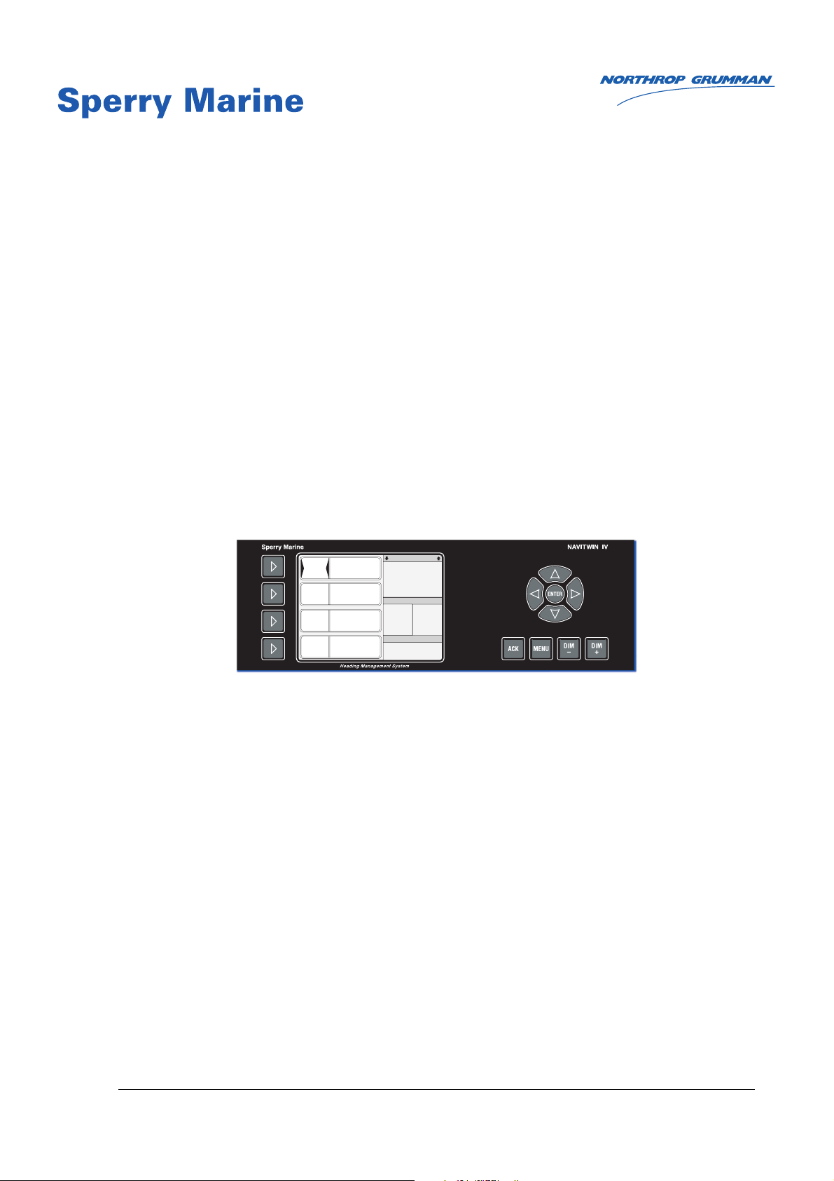
NAVI WIN IV
Heading Management System ype 4994-AB/AC
for GAS support
with Switch-Over Unit ype 4932
056360/E, 04994-0128-02, 27 Oct 2016

056360/E NAVITWIN IV
© 2016 Northrop Grumman Sperry Marine B.V.
This document and the information herein is and remain the intellectual property of Northrop
Grumman Sperry Marine B.V. NGSM BV] and it’s associate companies and may not be copied,
reproduced or translated without the express permission of NGSM BV.
A limited license is granted for the user to reproduce this documentation for his own internal
use, but not for distribution to third parties. Reproduction of this document for resale or com-
mercial gain is expressly prohibited.
Specifications were correct at time of press but may be varied in accordance with NGSM BV’s
policy of continuous product development.
Any technical content should be verified with NGSM BV.
Sperry Marine, with major engineering and support offices in New Malden, England, and
Hamburg, Germany, is part of the Northrop Grumman Navigation & Maritime Systems Division
N&MSD.
Revision Record
Rev. Date Remarks
E 27 Oct 2016 Update, SUSI software upload procedure amended
D2 17 Feb 2016 Update, CAM settings and alarm handling amended, alarm lists
enhanced
D1 05 Nov 2014 Update, external alarm and error list amended
D 30 Sep 2014 Updated version, alarm system and error list updated, usage info of
Central Alarm Management System and Central Dimming added
C 03 Mar 2014 Updated version, manual settings, user setup updated, service setup
amended regarding CAM interface, error list updated
B 13 Feb 2013 Reworked version, GAS heading substitution updated
A 23 Dec 2009 Initial version;
This manual applies to NAVITWIN IV types 4994-AB and 4994-AC for
GAS support. Manual 056344 remains valid for the now discontinued
NAVITWIN IV types 4994 and 4994-AA

NAVITWIN IV 056360/E
iii
Contents
Safety Instructions
Safety Notice Conventions ....................................................................... vii
General Safety Information for the Operator ........................................ viii
General Safety Information for Service Personnel ................................... x
Chapter 1: Introduction
1.1 System Information .................................................................................. 1-1
Intended Use ...............................................................................................1-1
Not Intended Use.........................................................................................1-1
1.2 Design and Main Features........................................................................ 1-2
NAVITWIN IV................................................................................................1-2
Switch-Over Unit, Type 4932........................................................................1-3
1.3 Standard System Configurations ............................................................ 1-4
Single NAVIGAT Gyrocompass/TMC System...............................................1-4
Dual NAVIGAT Gyrocompass Systems ........................................................1-5
Triple NAVIGAT Gyrocompass Systems .......................................................1-6
1.4 Support for G S according to DNV Naut- W ........................................ 1-7
1.5 Technical Data............................................................................................ 1-9
NAVITWIN IV................................................................................................1-9
Switch-Over Unit, Type 4932......................................................................1-12
1.6 Declaration of Conformity ...................................................................... 1-14
Chapter 2: Operation
2.1 Display and Operating Keys ..................................................................... 2-1
2.2 External control devices ........................................................................... 2-2
2.3 Power-up Sequence .................................................................................. 2-2
2.4 Selecting the active heading source ....................................................... 2-3
2.5 Selecting additional display data ............................................................ 2-4
2.6 djusting the illumination brightness .................................................... 2-5
2.7 Toggling between daylight/night colour schemes ................................ 2-5
2.8 Optional Functions.................................................................................... 2-6
Muting Alarms Remotely ............................................................................ 2-6
Resetting/Acknowledging a Central Watch Alarm ...................................... 2-6
Reversing the eading Display (180° offset)............................................... 2-6
External Dimming........................................................................................ 2-6
2.9 Operating Menu ........................................................................................ 2-7
Entering and Quitting the Menu Mode ....................................................... 2-7
Navigating the Menu................................................................................... 2-8
Selecting Parameter Settings...................................................................... 2-9
Editing Parameter Values ...........................................................................2-10

056360/E NAVITWIN IV
iv
2.10 Off Heading Monitor Settings ................................................................ 2-11
2.11 Heading Diff. Monitor Settings .............................................................. 2-12
2.12 Manual Settings Menu ........................................................................... 2-13
Manual Settings – Overview ..................................................................... 2-13
Manual Settings – Parameters .................................................................. 2-15
2.13 User Setup ............................................................................................... 2-19
User Setup – Overview ............................................................................. 2-19
User Setup – Parameters .......................................................................... 2-20
Chapter 3: Grounding voidance System (G S)
3.1 G S Heading Substitution ....................................................................... 3-1
3.2 G S utomatic Switch Over Functionality ............................................ 3-1
3.3 Sequence of Events and ctions ............................................................. 3-2
Chapter 4: larm System
4.1 C M Interface ............................................................................................ 4-1
4.2 larm Indication ........................................................................................ 4-2
Audible Alarm Indication.............................................................................. 4-2
Visual Alarm Indication ................................................................................ 4-3
4.3 cknowledging larms/Muting the udible larm............................... 4-4
Alarm Acknowledge at NAVITWIN IV.......................................................... 4-4
Alarm Mute from External Device............................................................... 4-5
4.4 Viewing ctive larms ............................................................................. 4-6
Viewing of Internal Alarms .......................................................................... 4-6
Viewing of External Alarms ......................................................................... 4-6
4.5 larm messages ........................................................................................ 4-7
Internal Alarms (from NAVITWIN IV) ........................................................... 4-7
External Alarms (from NAVIGAT Compasses) ............................................4-11
Chapter 5: Scheduled Maintenance
5.1 Maintenance by Shipboard Personnel .................................................... 5-1
Chapter 6: Installation
6.1 Mechanical Installation............................................................................. 6-1
NAVITWIN IV............................................................................................... 6-1
Switch-Over Unit, Type 4932....................................................................... 6-2
6.2 Electrical Installation................................................................................. 6-2
Wiring Up the System ................................................................................. 6-2
6.3 Initial System Configuration .................................................................... 6-2
6.4 Magnetic Compass Heading Calibration................................................. 6-3
Calibration Procedure .................................................................................. 6-3

NAVITWIN IV 056360/E
v
Chapter 7: System Configuration
7.1 Service Setup Menu.................................................................................. 7-1
Setup Access Code..................................................................................... 7-1
Service-Setup – Overview ........................................................................... 7-2
Service Setup – Parameters ........................................................................ 7-7
Chapter 8: Troubleshooting
8.1 General Troubleshooting Instructions..................................................... 8-1
NAVITWIN IV............................................................................................... 8-1
Switch-Over Unit, Type 4932....................................................................... 8-2
8.2 Location of Parts on the N VITWIN IV PCB ........................................... 8-3
Diagnostic LED Indicators ........................................................................... 8-4
Connectors.................................................................................................. 8-5
Exchangeable Components ........................................................................ 8-5
8.3 Location of Parts on the Switch-Over Unit PCB..................................... 8-6
Diagnostic LED Indicators ........................................................................... 8-7
Connectors.................................................................................................. 8-7
Chapter 9: Corrective Maintenance
9.1 Exchanging the System Software ........................................................... 9-1
Downloading Software from the Flashboard .............................................. 9-1
Uploading Software from a PC using SUSI ................................................. 9-4
Upload Procedure........................................................................................ 9-5
9.2 Replacing the RS-422 Output Driver IC ................................................. 9-10
9.3 Replacing the larm/Status Output Relays ......................................... 9-10
Chapter 10: N VITWIN IV Spare Parts
10.1 Illustrated Parts List (IPL) Overview ...................................................... 10-1
bbreviations
ppendix
Setup and Configuration Tables
Drawings

056360/E NAVITWIN IV
vi

NAVITWIN IV 056360/E
vii
Safety Instructions
Safety Notice Conventions
The following safety notice conventions are followed throughout this
manual:
D NGER
A Danger notice contains an operating or main-
tenance procedure, practice, condition, state-
ment, etc., which, if not strictly observed, will
result in injury or death of personnel.
W RNING
A Warning notice contains an operating or
maintenance procedure, practice, condition,
statement, etc., which, if not strictly observed,
could result in injury or death of personnel.
C UTION
A Caution notice contains an operating or main-
tenance procedure, practice, condition, state-
ment, etc., which, if not strictly observed, could
result in damage to, or destruction of equip-
ment.
Note
A Note contains an essential operating or main-
tenance procedure, condition or statement,
which is considered important enough to be
highlighted.
Special safety symbols may be used in this
manual to indicate:
Risk of electrical shock.
Used in conjunction with a Danger or Warning
notice.
Electrical components are sensitive to electro-
static discharge.
Used in conjunction with a Caution notice.
056360/E NAVITWIN IV
viii
General Safety Information for the Operator
W RNING
Risk of misusage
Before using the N VITWIN IV system, operators must be appropriately
trained and familiar with all operating procedures and safety instruc-
tions contained in this manual. The manual is to be completely read
before the first usage of the N VITWIN IV system.
Keep all system manuals in a well-known, readily available location
W RNING
Limited data accuracy during settling time
N VITWIN IV permits to activate a heading source as soon as valid
heading data is received from the respective device.
Make sure that a gyrocompass has settled before using its heading as
the reference for heading control systems, R D R, ECDIS, etc.
magnetic compass heading source should be made the active refer-
ence only in case of failure of the gyrocompass(es).
C UTION
Risk of erroneous operating conditions through inaccurate alignment
When the NAVITWIN IV is used in a system with the fiber-optic gyrocom-
pass NAVIGAT 2100 / NAVIGAT 3000:
At each new alignment (restart) of the NAVIGAT 2100 / NAVIGAT 3000,
make sure that the FOG aligns correctly, using valid speed and position
data.
The correctness of speed and position data must always be confirmed at
the respective FOG CDU each time a new alignment is carried out.
C UTION
Risk of erroneous operating conditions through inaccurate error alarm
recovering
When acknowledging an external alarm from a NAVIGAT 2100 /
NAVIGAT 3000, make sure that the FOG fully recovers from the error.
Upon alarm acknowledge, the NAVIGAT 2100 / NAVIGAT 3000 executes
the command which corresponds to confirming the alarm message, i.e.
pressing the F1 key, at the compass.
In certain cases, it may be necessary to take further action to return the
NAVIGAT 2100 / NAVIGAT 3000 to normal operation, e.g. it might be
required to change the speed or position data source or to execute a new
align (restart) of the system.
C UTION
Risk of erroneous CAM handling
Selecting ALR for the ALARM SELECT setting of RS-422 output 2 AND 3
simultaneously, will result in erroneous CAM handling.
Newer select ALR for the ALARM SELECT setting of RS-422 output 2 AND
3 simultaneously.
Always make sure to either select ALR for the ALARM SELECT setting of
RS-422 output 2 OR RS-422 output 2, and to select OFF or PPLAA/PPLAB/
PPLAD for the remaining RS-422 output.

NAVITWIN IV 056360/E
ix
Note
The NAVITWIN IV provides a serial bidirectional interface for a
centralized alarm management system (CAM) according to DNV class
notation NAUT-OC, NAUT-AW, NAUT_OSV.
The CAM functionality is available from software version:
NAVITWIN IV 4994-1091, Rev. E, 1.346,
NAVIGAT X MK1 4914-1290, Rev. L, 1.300,
NAVIGAT 2100 IPSU 4902-1090 Rev. L, 2.013 and
NAVIGAT 3000 IPSU 4902-1095 Rev. E, 2.301 on.
Note
For usage of the centralized alarm management system (CAM) according
to DNV class notation NAUT-OC, NAUT-AW, NAUT-OSV,
the NAVITWIN IV and the relevant gyrocompass(es) need appropriate
software update.
056360/E NAVITWIN IV
x
General Safety Information for Service Personnel
W RNING
Risk of electrical shock or burn
lways make sure that the power supplies for the N VITWIN IV and
Switch-Over Unit are switched off and safeguarded against accidental
switching-on, when wiring up the system.
W RNING
Risk of electrical shock or burn
Hazardous voltage is present inside the N VITWIN IV.
Danger of electrical shock or burn may occur when the CCFL inverter
connections are touched.
Disconnect power before opening the device.
Never touch the PCB when servicing the device without the back cover
installed and while power is applied to the board.
C UTION
Risk of damage of electrostatic-discharge-sensitive components
The NAVITWIN IV system contains electrostatic sensitive components.
Electrostatic discharge may permanently damage components.
When servicing the NAVITWIN IV, take precautions to prevent electro-
static discharge. Avoid touching any of the electronic circuitry.
C UTION
Risk of erroneous CAM handling
Selecting ALR for the ALARM SELECT setting of RS-422 output 2 AND 3
simultaneously, will result in erroneous CAM handling.
Newer select ALR for the ALARM SELECT setting of RS-422 output 2 AND
3 simultaneously.
Always make sure to either select ALR for the ALARM SELECT setting of
RS-422 output 2 OR RS-422 output 2, and to select OFF or PPLAA/PPLAB/
PPLAD for the remaining RS-422 output.
Note
For parallel usage of a Central Alarm Management System (CAM) and a
Central Dimming Device, a multiplexer device must be used for the
shared RS422 interface at J6.36 / J6.37 of the NAVITWIN IV.
All the central dimming input settings remain active with input baudrate
set to 4800 baud.
C UTION
Risk of loss of parameter settings through software exchange
It cannot be guaranteed that parameter settings in the User and Setup
menus and the entries made in the Magnetic Compass Calibration table
are left intact during an exchange of the system software.
Before exchanging the flash-memory chip, IC 9, record all parameter set-
tings to be able to re-enter them manually, if required.
NAVITWIN IV 056360/E
xi
C UTION
Risk of inoperable device state
Updating a device’s firmware using the FlashUpdate mode is a risky
operation, as SUSI writes directly to the device’s flash memory. Further-
more, SUSI cannot verify whether the file supplied is indeed intended for
the device under service.
Under adverse circumstances, a failed update attempt may leave the
device in an inoperable state from which it can only be recovered by
replacing the flash memory chip.
Always maintain a stable power supply during the update process.
Never interrupt an update in progress.
Note
The UpdateFlash Mode may equally be used either via RS-232 cable or
via USB standard connection.
For Sperry devices equipped with a USB port, the safer and more
convenient update mode via USB connection is recommended.
When SUSI is installed under Windows 10™, the UpdateFlash mode via
USB port is not available for the NAVITWIN IV CDU.
Note
The exemplary screens in the FlashUpdate mode procedure present are
produced with the SUSI application installed under Windows XP™.
For procedures with SUSI installed under Windows 7™ and higher, refer
to the SUSI Installation Guide, Sperry document no. 056358.

056360/E NAVITWIN IV
xii

NAVITWIN IV 056360/E
System Information 1-1
Chapter 1: Introduction
1.1 System Information
Intended Use
The Heading Management System NAVITWIN IV is a central control and
display device for multi-compass systems for the maritime navigation of
vessels.
The NAVITWIN IV can be configured to perform a number of different
functions such as:
• Heading Source Selector
• Heading Difference Monitor
• Off Heading Monitor
• Magnetic Compass Heading Source
• Central Gyrocompass Control Unit
• Heading Source for Grounding Avoidance System (GAS) or Track
Control System (TCS)
• Centralized Alarm Management (CAM) support by means of a serial
bidirectional interface
The usage of the NAVITWIN IV for the navigation of Offshore Service
Vessels (OSV) is only allowed when the Heading Difference Monitor and
Off Heading Monitor functions are deactivated.
The Heading Management System NAVITWIN IV must only be operated
from appropriately trained and educated personnel familiar with all
mandatory safety and operating procedures.
Not Intended Use
The Heading Management System NAVITWIN IV central control and dis-
play device for multi-compass systems is not allowed to be used for the
navigation of inland water vessels and river boats.
The usage of the NAVITWIN IV for the navigation of Offshore Service
Vessels (OSV) is not allowed with active Heading Difference Monitor and
Off Heading Monitor functionality.
Since the NAVITWIN IV is used for displaying secondary navigation data
(heading input data) generated from other connected devices, the oper-
ator must not take displayed secondary data for granted and is obliged
to confirm the validity of secondary data independently.

056360/E NAVITWIN IV
1-2 Design and Main Features
1.2 Design and Main Features
N VITWIN IV
The Heading Management System NAVITWIN IV is a central control and
display device for multi-compass systems for the maritime navigation of
vessels.
The NAVITWIN IV has been type approved by Germanischer Lloyd (GL),
in association with the Marine Equipment Directive (MED) 96/98/ EC, as
amended, as Heading Management System optional with the Gyrocom-
pass Systems
NAVIGAT MK1 (certificate no. 94 418-10 HH, 94 428-10 HH),
NAVIGAT MK2 (certificate no. 94 420-10 HH),
NAVIGAT 2100 (certificate no. 94 416-10 HH, 94 426-10HH) and
NAVIGAT 3000 (certificate no. 37 757-12 HH, 37 957-12 HH).
The NAVITWIN IV is compliant with the requirements of DNV rules for
Ships Pt.6 Ch.8 and Ch.20 with regard to distribution of heading infor-
mation.
The automatic heading switch over functionality of the NAVITWIN IV as
part of a Grounding Avoidance System (GAS) is in compliance with rules
according to DNV Naut-AW.
The NAVITWIN IV provides a serial bidirectional interface for a central-
ized alarm management system (CAM) according to DNV class notation
NAUT-OC, NAUT-AW.
The NAVITWIN IV is also compliant with NAUT-AW/OSV class require-
ments for offshore service vessels (OSV), with deactivated Heading Dif-
ference Monitor and Off Heading Monitor functionality, see “Off
Heading Monitor Settings” on page 2-11, "Heading Diff. Monitor Set-
tings" on page 2-12 and "CAM Interface" on page 4-1 for details.
For further details see also "Declaration of Conformity" on page 1-14.
Depending on the system at hand, the NAVITWIN IV may be configured
to perform a number of different functions:
• Heading source selector
The NAVITWIN IV displays heading data from up to three true head-
ing sources and one magnetic compass heading source.
By selecting the active heading source at the NAVITWIN IV, the oper-
ator determines which source is to be used as the reference for dis-
tribution via the Switch-Over Unit to other equipment, such as
compass repeaters, heading control systems, RADAR, ECDIS etc.
• Heading difference monitor
NAVITWIN IV can monitor the difference between any two of the
connected heading sources. Should this difference exceed a user-
defined threshold, a “Heading Difference Alarm” is raised.
• Off heading monitor
In automatic steering modes, NAVITWIN IV can monitor the differ-
ence between the actual heading from the active source and the
commanded set heading. Should this difference exceed a user-
defined threshold, an “Off Heading Alarm” is raised. The set heading
may be received automatically from a heading control system or

NAVITWIN IV 056360/E
Design and Main Features 1-3
may be entered manually.
• Magnetic compass heading source
In conjunction with a Sperry Marine fluxgate sensor type 4863, fitted
to a compatible magnetic compass, NAVITWIN IV senses the ves-
sel‘s magnetic compass heading and converts it to the NMEA 0183
(IEC 61162) format, including automatic correction for magnetic vari-
ation and sensor calibration values.
• Central gyrocompass control unit
In single, dual and triple gyrocompass systems comprising current
models from the NAVIGAT gyrocompass line, the NAVITWIN IV acts
as the system‘s central control and display unit.
System-wide operational settings are entered at the NAVITWIN IV
and transmitted to the connected compasses. In turn, alarm mes-
sages from the gyrocompasses are indicated and may be acknowl-
edged at the NAVITWIN IV.
• Heading source for Grounding Avoidance Systems
The NAVITWIN IV may form part of a grounding avoidance system
(GAS) according to DNV.
In case of failure of the active heading source, substitute heading
data is automatically provided to the GAS by smoothly changing
over from the last known heading of the active source to the current
heading of a secondary (none-active) source.
Switch-Over Unit, Type 4932
The Switch-Over Unit (SOU), type 4932, is a passive data distribution
unit, which is able to switch a large number of data and signal outputs
from one source to another.
Through control signals from the NAVITWIN IV, the SOU may be put in
either one of three source selection modes:
G1: Connects the outputs to the inputs from source “G1”.
G2: Connects the outputs to the inputs from source “G2”.
M: Connects the repeater and sensor data outputs to the data input
from the NAVITWIN IV.
In case of failure of the gyrocompass(es), magnetic compass head-
ing data is available at these outputs as an emergency heading refer-
ence for repeaters and other external equipment.
All other outputs are connected to the corresponding inputs from
source “G1”.
The SOU uses electro-mechanical relays for switching signal and data
lines. As the unit is designed to be used in conjunction with Sperry
Marine‘s NAVIGAT gyrocompasses, the designations of the in- and out-
puts largely correspond to those of the outputs at the NAVIGAT X MK 1,
X MK 2, and NAVIGAT 2100 / NAVIGAT 3000.
The repeater data (TTL) and single-ended signal lines share a common
ground connection, while data lines for general use (RS-422) are electri-
cally isolated from each other and are all-pole switched.
056360/E NAVITWIN IV
1-4 Standard System Configurations
1.3 Standard System Configurations
The NAVITWIN IV with Switch-Over Unit type 4932 is an integral part of
Sperry Marines standard single, dual and triple gyrocompass configura-
tions with NAVIGAT X MK1, X MK2 gyrocompasses and NAVIGAT 2100
NAVIGAT 3000 FOGs.
Single N VIG T Gyrocompass/TMC System
In a single gyrocompass system with the NAVIGAT X MK 1, X MK 2 or
NAVIGAT 2100 / NAVIGAT 3000, the NAVITWIN IV‘s main function is to
provide an independent magnetic compass heading source (TMC func-
tion).
In case of failure of the gyrocompass, the magnetic compass may be
used as emergency heading reference for repeaters and other external
equipment.
The NAVITWIN IV may receive an analogue sine/cosine signal from the
Sperry Marine fluxgate sensor, type 4863, or may receive NMEA head-
ing data from an electronic compass.
The NAVITWIN IV applies magnetic variation to the raw sensor value
and provides a correction table to compensates for the sensor‘s devia-
tions from the magnetic compass heading.
The “heading diff.” alarm function permits to monitor the gyrocompass
against the magnetic compass heading. The “off heading” alarm func-
tion permits to monitor the difference between the actual heading and
the heading to steer received from a heading control system.
Operating parameters entered at the NAVITWIN IV are transmitted to
the NAVIGAT gyrocompass. In turn, alarms generated by the compass
are indicated and may be acknowledged at the NAVITWIN IV.
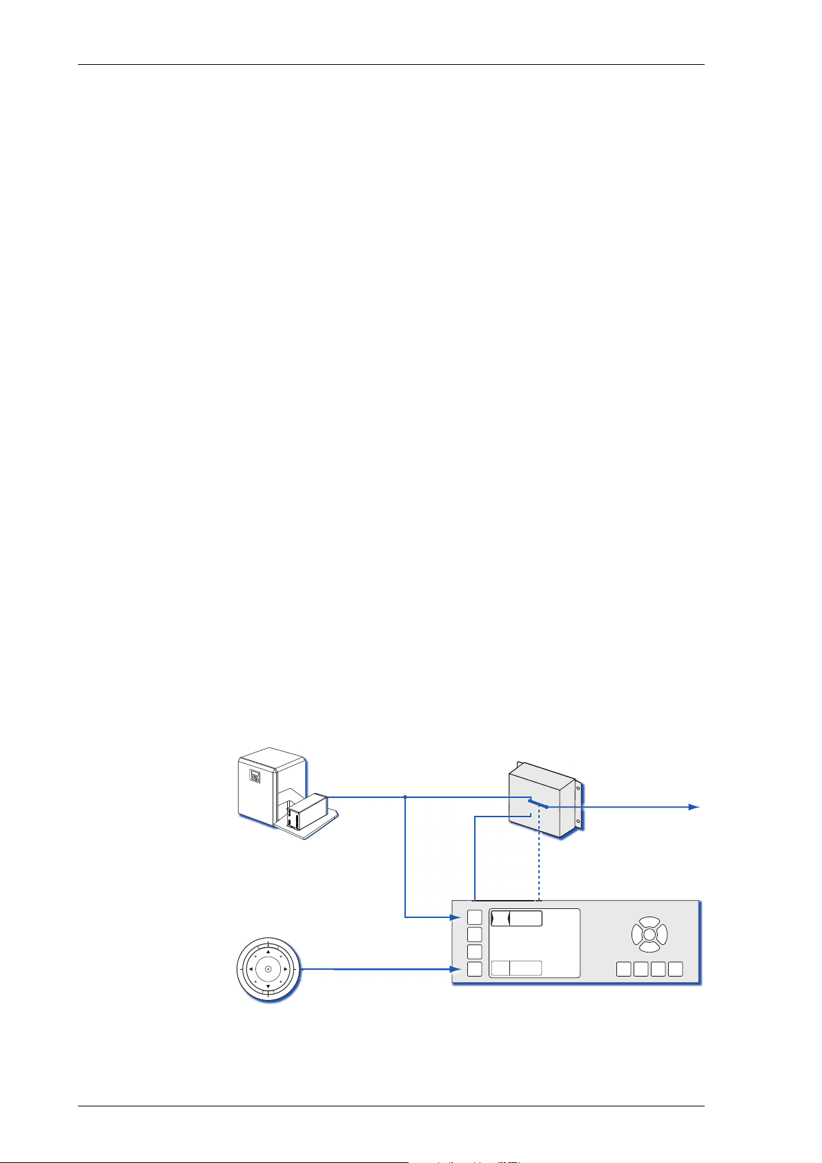
Figure 1-1 below illustrates how the active source selection at the
NAVITWIN IV controls the distribution of data from the gyrocompasses,
via the Switch-Over Unit, to external equipment.
Figure 1-1:
Data distribution in
a NAVIGAT *single gyro-
compass / TMC system
* The NAVIGAT 3000 is as well representative for the NAVIGAT 2100,
not shown in the above figure.
GYRO
1
MAGN
COMP
246.8
247.0
Switch-Over Unit
NAVITWIN IV
source selection
to external
equipment
mag. hdg.
Magnetic
Compass
NAVIGAT X MK 1,
NAVIGAT X MK 2 or
NAVIGAT 3000
G/M
NAVITWIN IV 056360/E
Standard System Configurations 1-5
Dual N VIG T Gyrocompass Systems
Standard dual gyrocompass configurations with NAVIGAT X MK 1 or
NAVIGAT 2100 / NAVIGAT 3000 gyrocompasses include a NAVITWIN IV
as the system‘s central operating unit and a Switch-Over Unit to distrib-
ute data from the compasses to external equipment.
At the NAVITWIN IV, either one of the gyrocompasses may be activated
to become the heading reference for external equipment, such as head-
ing control systems, RADAR, compass repeaters etc.
In conjunction with a Sperry Marine fluxgate sensor, type 4863, or an
electronic compass, the NAVITWIN IV also provides an independent
magnetic compass heading source (TMC function).
In case of failure of both gyrocompasses, the magnetic compass may be
activated to provide an emergency heading reference for repeaters and
other peripheral equipment.
The NAVITWIN IV applies magnetic variation to the raw sensor value
and provides a correction table to compensates for the sensor‘s devia-
tions from the magnetic compass heading.
The “heading diff.” alarm function permits to monitor the gyrocom-
passes against each other or against the magnetic compass heading.
The “off heading” alarm function permits to monitor the difference
between the actual heading and the heading to steer received from a
heading control system.
Operating parameters entered at the NAVITWIN IV are transmitted to
the NAVIGAT gyrocompasses. In turn, alarms generated by the com-
passes are indicated and may be acknowledged at the NAVITWIN IV.
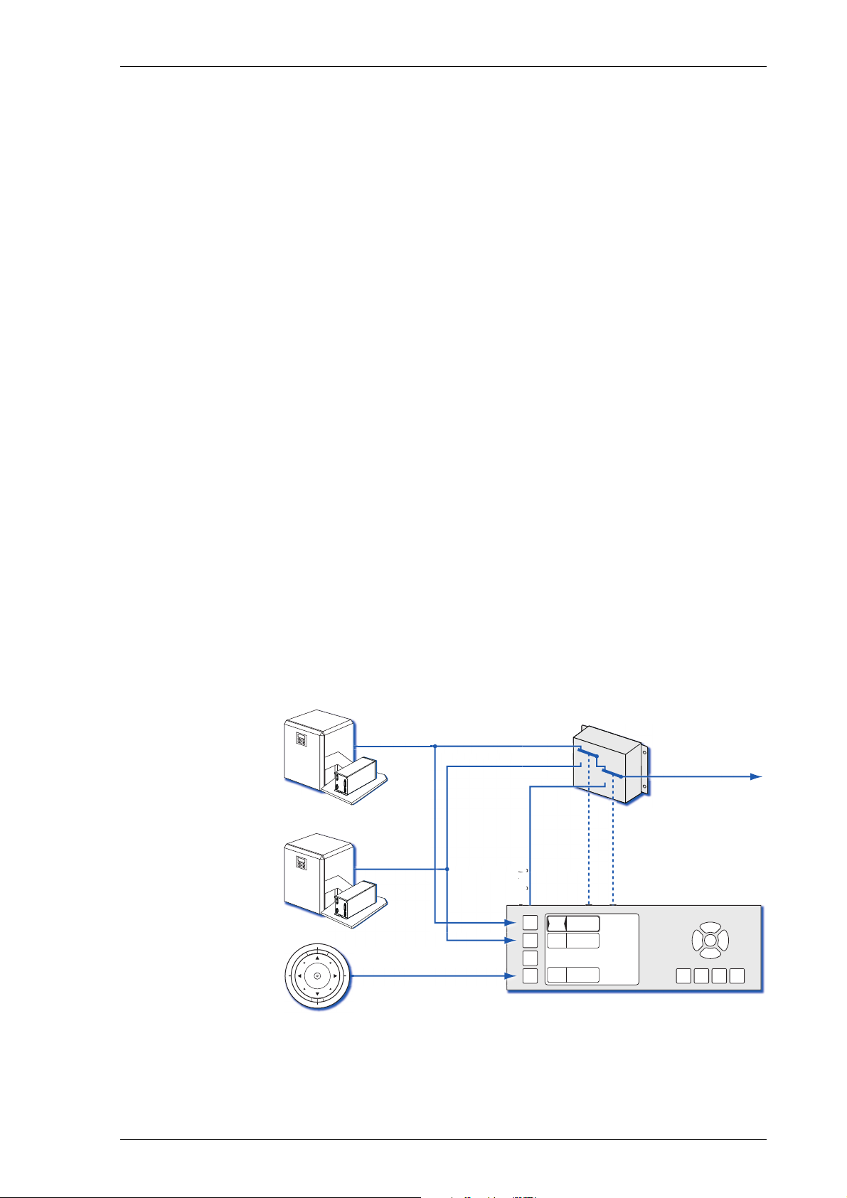
Figure 1-2 below illustrates how the active source selection at the
NAVITWIN IV controls the distribution of data from the compasses, via
the Switch-Over Unit, to external equipment.
Figure 1-2:
Data distribution in
a NAVIGAT *dual gyro-
compass / TMC system
* The NAVIGAT 3000 is as well representative for the NAVIGAT 2100,
not shown in the above figure.
GYRO
1
MAGN
COMP
246.8
247.0
GYRO
2
246.7
NAVITWIN IV
source selection
Switch-Over
Unit
to external
equipment
mag. hdg.
mag
mag
mag
. h
dg.
dg.
dg.
dg.
dg.
dg.
dg.
mag. hdg.
. hdg.
dg.
dg.
Magnetic
Compass
NAVIGAT X MK 1 or
NAVIGAT 3000
NAVIGAT X MK 1 or
NAVIGAT 3000
G/M
G1/G2
NAVIGA
NAVIGA

056360/E NAVITWIN IV
1-6 Standard System Configurations
Triple N VIG T Gyrocompass Systems
Triple gyrocompass systems with NAVIGAT X MK 1 or NAVIGAT 2100 /
NAVIGAT 3000 gyrocompasses include a NAVITWIN IV as the system‘s
central operating unit and two cascaded Switch-Over Units to distribute
data from the compasses to external equipment.
At the NAVITWIN IV, any of the gyrocompasses may be activated to
become the heading reference for external equipment, such as heading
control systems, RADAR, compass repeaters etc.
In conjunction with a Sperry Marine fluxgate sensor, type 4863, the
NAVITWIN IV also provides an independent magnetic compass heading
source (TMC function). In case of failure of all three gyrocompasses, the
magnetic compass may be activated to provide an emergency heading
reference for repeaters and other peripheral equipment.
The NAVITWIN IV applies magnetic variation to the raw sensor value
and provides a correction table to compensates for the sensor‘s devia-
tions from the magnetic compass heading.
The “heading diff.” alarm function permits to monitor any two of the
gyrocompasses against each other or any gyrocompass against the
magnetic compass heading.
The “off heading” alarm function permits to monitor the difference
between the actual heading and the heading to steer received from a
heading control system.
Operating parameters entered at the NAVITWIN IV are transmitted to
the NAVIGAT gyrocompasses. In turn, alarms generated by the com-
passes are indicated and may be acknowledged at the NAVITWIN IV.
Figure 1-3 below illustrates how the active source selection at the
NAVITWIN IV controls the distribution of data from the compasses, via
the Switch-Over Unit, to external equipment.
Figure 1-3:
Data distribution in
a NAVIGAT *Triple gyro-
compass / TMC system
* The NAVIGAT 3000 is as well representative for the NAVIGAT 2100,
not shown in the above figure.
GYRO
1
246.8
MAGN
COMP
247.0
GYRO
2
246.7
GYRO
3
246.6
Switch-Over
Unit
to external
equipment
NAVITWIN IV
source selection
Switch-Over
Unit
mag. hdg.
Magnetic
Compass
NAVIGAT X MK 1 or
NAVIGAT 3000
NAVIGAT X MK 1 or
NAVIGAT 3000
NAVIGAT X MK 1 or
NAVIGAT 3000
G/M
G/G3
G1/G2
NAV
IGA
NAV
IGA
GYR
GYR
GYR
GYR
GYR
GYR
GYR
GYR
GYRO
GYRO
GYRO
GYR
GYR
GYR
GYR
GYR
GYR
GYR
GYR
GYR
GYR
GYR
GYR
GYR
246.8
mag. hdg.
mag
dg.
mag
. h
dg.
mag
. h
dg.
dg.
. h
. h
dg.
dg.
G/G
G/G
G/G
3
3
3
G/G
G/G
G/G
G/G
G/G
G/G
G/G
G/G
G/G
G/G
3
3
3
3
3
3
3
3
3
3
G1/G2
NAVIGA

NAVITWIN IV 056360/E
Support for GAS according to DNV Naut-AW 1-7
1.4 Support for G S according to DNV Naut- W
The NAVITWIN IV may act as part of a grounding avoidance system
(GAS) according to DNV class notation Naut-AW.
For this purpose, the NAVITWIN IV in GAS mode provides a dedicated
GAS serial data output for connection to a GAS-enabled track control or
integrated navigation system (INS). A GAS warning status output (relay
contact) is also provided for connection to the bridge alarm manage-
ment system. Additionally the switch over unit (SOU) is triggered to
switch the heading distribution abruptly to the secondary source.
During normal operation, the GAS serial data output behaves identical
as a regular data output.
Should, however, the active heading source fail, the GAS output auto-
matically generates substitute heading data by changing over from the
last known heading of the active source to the current heading of a sec-
ondary (previously none-active) source. Parallel to this, the SOU
switches abruptly to the secondary source and new heading data are
immediately transmitted to all the external devices, connected to the
NAVITWIN IV´s outputs other than the dedicated GAS serial data output.
Internally, once the GAS heading substitution has been triggered, the
secondary source is taken as the new heading reference. To prevent
sudden rudder actions, the NAVITWIN IV performs a gradual transition
from the last valid heading of the failed source to the actual heading
from the secondary, now active, source on the NAVITWIN IV‘s dedicated
GAS serial data output only.
The track control or INS connected to the GAS data output will thus be
unaware of the failure of the former active heading source. Thus, e.g. a
track controller or INS will continue to operate without disruption and
will not deviate from the track. This allows the operator to take all neces-
sary measures to recover from the loss of heading without having to
deal with a loss of track control at the same time.
Heading substitution will continue, even when the operator changes to
the manual steering mode, e.g. to gain an overview of the navigational
situation. Heading substitution will only be terminated if the operator
manually selects one remaining heading sources as the active heading
reference.
Figure 1-4 on page 1-8 shows an UML activity diagram with the specific
activities relating to the NAVITWIN IV‘s GAS functionality in case of a
failure of the active heading source. See also "Grounding Avoidance
System (GAS)" on page 3-1 for further details.
Note
At the time of writing of this manual, only DNV class notation Naut-AW
calls for a grounding avoidance system.
Activate the GAS functionality only if the NAVITWIN IV has been incorpo-
rated into the bridge system design as part of a grounding avoidance sys-
tem according to DNV Naut-AW.
Note
The NAVITWIN IV provides automatic heading switch over functionality
in auto steering mode and manual steering mode.
An active gyrocompass or other true heading source and another none-
active true heading source with a heading below GAS threshold are man-
datory for the GAS functionality.

056360/E NAVITWIN IV
1-8 Support for GAS according to DNV Naut-AW
Figure 1-4: GAS activities following a loss of the active true heading reference
start
secondary gyro hdg
available AND difference
between last active and
secondary hdg below GAS
threshold AND GAS on
run GAS mode
manage GAS warning
raise GAS warning
talarm buzzer on
tvisual indication flashing
generate substitue hdg
set inital
parameters
tD = last active hdg - secondary hdg
(hdg diff., °)
tTc = time constant (°/min)
operator
acknowledges
GAS warning
acknowledge GAS
warning
talarm buzzer off
tvisual indication solid
start
start
D = D - scaled_degree
D < scaled_degree?
compute substitute
hdg with D
show substitute hdg in
display (red, flashing)
substitute hdg = secondary hdg
transmit substitute hdg
at RS-422 output 3
tx_clk
substitution
finished
start
Changing to Manual Mode
does not terminate GAS
heading substitution
switch to secondary
hdg source
tstatus relay gyro1/gyro2
tstatus relay gyro/gyro3
tstatus relay gyro1/magnet
tRS-422 output 1
tRS-422 output 2
scaled_degree = scale Tc to
update_clk
update_clk
GAS heading substitution
is available in all
steering modes
set GAS status relay
inactive
set GAS status
relay active
add a minus-sign to
scaled_degree if D is
negative
Y
N
Y
N
act generating substitute heading after failure of active gyro
set visual
indication of GAS
warning off
Table of contents


