NORTHROP GRUMMAN Park Air T6-RV Operator's manual

Park Air
T6-RV VHF Receiver
User Documentation

Product Code: T6-D-USER-RV-EN
Product Code Identification Number: 31-30T6RVEN/1
Version 1.1
Date of Issue: February 2016
Published By: Northrop Grumman
Park Air Systems Ltd
Northfields
Market Deeping
Peterborough PE6 8UE
UK
Telephone: From UK, 01778 345434
From outside UK, +44 1778 345434
Email [email protected]
Web site: www.northropgrumman.com/ParkAir
© Park Air Systems Ltd 2015
All rights reserved. No part of this publication may be reproduced or transmitted in any form or by
any means, electronic, mechanical, photocopying, recording or otherwise without the prior
permission of the publisher.
This information and intellectual property contained herein is confidential between
Northrop Grumman and the client and remains the exclusive property of Northrop Grumman.
Northrop Grumman does not warrant that this document is error free.

T6-D-USER-RV-EN Page iii
© Park Air Systems Ltd 2015
Foreword
This user documentation gives the necessary information for a user to install and understand the operation of the
radio supplied by Northrop Grumman.
Copyright and trademarks
This documentation could contain information provided by other equipment manufacturers. It is acknowledged
that the copyright of any third party information is retained by the respective holder. Similarly, any trademarks
and protected names or symbols contained in this documentation, or associated documentation, belong to their
respective holder.
Amendments and modifications
Amendments to this documentation are listed below.
Modifications are listed below.
Note:
This documentation contains sections of text and text in tables that are ‘greyed out’ .
These reflect radio functionality and documentation that are under revision.
Amendment
number
Incorporated
by Date Brief details
Modification
state
Embodied
by Date Brief details

T6-D-USER-RV-EN Page iv
© Park Air Systems Ltd 2015
Health and safety
Disposal
This equipment is covered by the European Directive 2012/19/EU.
Items must not be disposed of in domestic waste.
Disposal must be made using designated collection facilities appointed by the government
or the local authorities in your area.
RoHS Directive 2011/65/EU compliant.
Warnings
A warning is used to show possible danger to personnel. In this documentation, warnings are shown by the
following symbols:
Cautions
A caution is used to show possible danger to the equipment. In this documentation, cautions are shown by the
following symbols:
Shows electrical danger to personnel
Shows a specified danger to personnel
Shows the presence of electrostatic sensitive devices (ESDs)
Shows a specified danger to the equipment

T6-D-USER-RV-EN Page v
© Park Air Systems Ltd 2015
You must be suitably qualified to terminate a mains supply to the equipment.
There are no user serviceable parts inside the radio. Access to the fan is from the rear of the radio.
The radio uses a power supply which has both live and neutral fuses.
The AC socket-outlet must be installed near the radio and must have easy access.
This equipment must be earthed. The earth terminal of the AC connector must be used as the safety earth.
The power cord/s is/are the radio’s disconnect supply device/s.
The radio AC supply must have a 5 Amp time-delay fuse fitted.
Changes or modifications made to equipment without the approval of Northrop Grumman, or parties
authorized by Northrop Grumman, could invalidate the user’s authority to operate the equipment.
Modern electronic equipment contains Electrostatic Sensitive Devices (ESDs). Use necessary precautions to
prevent damage to such devices.
Dangerous voltage
No user serviceable parts inside the radio
Double pole/neutral fusing
AC socket-outlet
Earth connection
AC and/or DC supply
AC supply fuse rating
Unauthorized modifications
ESDs

T6-D-USER-RV-EN Page vi
© Park Air Systems Ltd 2015
Park Air Services
Use email, telephone or fax to contact Park Air Services. For help with configuration, installation or maintenance
of equipment, use any of the contact methods listed below.
Email: [email protected]
Telephone (24 hours): Within the UK, 01778 381557
International, +44 1778 381557
Mail: Customer Services Department
Northrop Grumman
Park Air Systems Ltd
Northfields
Market Deeping
Peterborough PE6 8UE
UK
Web Site: www.northropgrummaninternational.com/capabilities/aviation-customer-support

T6-D-USER-RV-EN Page vii
© Park Air Systems Ltd 2015
Approvals and standards
Approvals
CE R&TTE Directive 1999/5/EC/RED 2014/53/EU
Standards
EMC EMC EN 301 489-22 v1.3.1 2003-11
Safety BS EN 60950-1:2010
AM Voice EN 300 676-1 v1.5.2 2011-03

T6-D-USER-RV-EN Page viii
© Park Air Systems Ltd 2015
CE type approval
ĞĐůĂƌĂƚŝŽŶŽĨĐŽŶĨŽƌŵŝƚLJ
ŽŵƉĂŶLJ
ŝŶĨŽƌŵĂƚŝŽŶ
WĂƌŬŝƌ^LJƐƚĞŵƐ>ŝŵŝƚĞĚ;ĂǁŚŽůůLJŽǁŶĞĚƐƵďƐŝĚŝĂƌLJŽĨEŽƌƚŚƌŽƉ
'ƌƵŵŵĂŶŽƌƉŽƌĂƚŝŽŶͿ
EŽƌƚŚĨŝĞůĚƐDĂƌŬĞƚĞĞƉŝŶŐWĞƚĞƌďŽƌŽƵŐŚWϲϴh
нϰϰϭϳϳϴϯϰϱϰϯϰ
WƌŽĚƵĐƚŵŽĚĞůĂŶĚ
ĚĞƐĐƌŝƉƚŝŽŶ
WZ</Zdϲ
dϲͲZs
'ƌŽƵŶĚƚŽĂŝƌƌĞĐĞŝǀĞƌĨŽƌƵƐĞŝŶƚŚĞs &ĂĞƌŽŶĂƵƚŝĐĂůďĂŶĚƵƐŝŶŐ
ϮϱϴϯϯŬ njĐŚĂŶŶĞůƐƉĂĐŝŶŐ
^ƚĂŶĚĂƌĚƐ EϲϬϵϱϬͲϭ;ϮϬϬϲнϭϮϬϭϬŝŶĐŽƌƉŽƌĂƚŝŶŐĂŵĞŶĚŵĞŶƚϭϭϮϬϬϵͿ
EϯϬϭϰϴϵͲϮϮ;sϭϯϭϮϬϬϯͲϭϭͿ
EϯϬϬϲϳϲͲϭ;sϭϱϮϮϬϭϭͲϬϯͿEϯϬϬϲϳϲͲϮ;sϭϱϭϮϬϭϭͲϬϵͿ
DĂƌŬĂŶĚŶŽƚŝĨŝĞĚ
ďŽĚLJ
dms^mWƌŽĚƵĐƚ^ĞƌǀŝĐĞ
KĐƚĂŐŽŶ ŽƵƐĞŽŶĐŽƌĚĞtĂLJ^ĞŐĞŶƐǁŽƌƚŚEŽƌƚŚ&ĂƌĞŚĂŵ
ĂŵƉƐŚŝƌĞWKϭϱϱZ>
dŚĞƉƌŽĚƵĐƚŚĂƐďĞĞŶƚĞƐƚĞĚƚŽƚŚĞůŝƐƚĞĚƐƚĂŶĚĂƌĚƐĂŶĚŝƐĐŽŶĨŝƌŵĞĚĂƐďĞŝŶŐŝŶĐŽŵƉůŝĂŶĐĞ
ǁŝƚŚƚŚĞĞƐƐĞŶƚŝĂůƌĞƋƵŝƌĞŵĞŶƚƐĂŶĚƉƌŽǀŝƐŝŽŶƐŽĨŝƌĞĐƚŝǀĞϭϵϵϵϱ
dŚĞĐŽŶĨŽƌŵŝƚLJĂƐƐĞƐƐŵĞŶƚƉƌŽĐĞĚƵƌĞƌĞĨĞƌƌĞĚƚŽŝŶƌƚŝĐůĞϭϬĂŶĚĚĞƚĂŝůĞĚŝŶŶŶĞdž/sŽĨ
ƚŚĞŝƌĞĐƚŝǀĞϭϵϵϵϱŚĂƐďĞĞŶĨŽůůŽǁĞĚǁŝƚŚƚŚĞŝŶǀŽůǀĞŵĞŶƚŽĨƚŚĞŶŽƚŝĨŝĞĚďŽĚLJ
dŚĞƚĞĐŚŶŝĐĂůĚŽĐƵŵĞŶƚĂƚŝŽŶƌĞůĞǀĂŶƚƚŽƚŚĞƉƌŽĚƵĐƚǁŝůůďĞŚĞůĚĂƚWĂƌŬŝƌ^LJƐƚĞŵƐ>ŝŵŝƚĞĚ
ĨŽƌŶŽƚůĞƐƐƚŚĂŶƚĞŶLJĞĂƌƐĂĨƚĞƌƚŚĞůĂƐƚƉƌŽĚƵĐƚŚĂƐďĞĞŶŵĂŶƵĨĂĐƚƵƌĞĚ
EĞŝůhƉƚŽŶ
dĞĐŚŶŝĐĂůŝƌĞĐƚŽƌWĂƌŬŝƌ^LJƐƚĞŵƐ ŝŵŝƚĞĚ

T6-D-USER-RV-EN Page ix
© Park Air Systems Ltd 2015
About this user documentation
This user documentation has eight sections:
Section 1. Overview
Section 2. Description - the human machine interface and detailed connectivity
Section 3. Installation - standalone, the Park Air C4 cabinet and legacy T6 cabinet
Section 4. Operation - how to use the Park Air T6-RV
Section 5. Maintenance - periodic tasks and part replacement
Section 6. Connector information - interface types and levels
Section 7. Specification
Section 8. Associated equipment
Quick Start - a copy of the Quick Start guide supplied with the radio
Index - to help the reader find keywords and topics.
A cross-reference to a section is shown as the section or sub-section number and the title. An example is, 4.3.2
How to set a radio configuration.
A cross-reference to a page is shown as the page number. An example is, page 4-3.
A glossary of terms can be found in Glossary of abbreviations, acronyms and technical terms on page x. To help
the reader, the first time a term is used in the book, it is italicized and emboldened. An example is, main/standby.
A table of associated equipment from the Park Air Sapphire range can be found in Associated equipment. To help
the reader, the first time a product is mentioned in the book, it is italicized. An example is Park Air C4 cabinet.
The electronic (PDF) version of this documentation has text-links to help the reader navigate topics as shown in
the examples:
AC Input
AC input connector
Connector Connection Characteristics
AC input
IEC-C14
chassis plug
Neutral
Input supply: 99 to 264 V AC. Frequency: 47 to 63 Hz.
No more than 55 VA under any condition.
Earth
Live
Note:
The connections are shown as viewed on the rear panel of the radio.
Example
Example

T6-D-USER-RV-EN Page x
© Park Air Systems Ltd 2015
Glossary of abbreviations, acronyms and technical terms
A Ampere
AC alternating current
ACARS aircraft communications addressing and reporting system
Active The radio is operationally active (IP RRC terminology)
AGC automatic gain control
ALC automatic level control
AM amplitude modulation
ATC air traffic control
ATM air traffic management
baud symbol rate or modulation rate in symbols per second or pulses per second
BIT built-in-test
co-location A location with multiple radio channels and/or users
CPLD complex programmable logic device
dB decibel
dBm dB relative to 1 mW
dBr dB relative to a specified level
DC direct current
E1 E-carrier system frame structure (ITU-T adopted)
ESD electrostatic sensitive device
ED-137 Interoperability standards for VoIP ATM components
Ethernet Computer network technologies
E-BIT external bit signal
GPS Global Positioning System
HDB3 coding High density bipolar of order 3 used in European E-carrier system
HTTPS Hypertext transfer protocol within a connection encrypted by transport layer security (TLS)
Hz Hertz
IEC International Electrotechnical Commission
Inactive The radio is operationally inactive (IP RRC terminology)
Inhibit(ed) A function in the radio is stopped
IP Internet Protocol
ITU-T International Telecommunication Union - Telecommunications Standardisation Sector
kg kilogram
LAN local area network
LED light emitting diode
mmetre
MAC media access control
Main/standby The radio is operationally main or standby (analogue radio control terminology)
MARC multi access remote control
Mbits megabits
Mute Transmit audio/audio level is prevented
Network Jitter Variation in packet transit delay

T6-D-USER-RV-EN Page xi
© Park Air Systems Ltd 2015
Glossary of abbreviations, acronyms and technical terms (continued)
Off-air standard An extremely high stability RF frequency source, for example GPS
OLED organic light emitting diode
Ohm unit of resistance
Phantom PTT DC control voltage applied to transmit audio input lines
Phantom Squelch DC control voltage applied to receive audio output lines
pk-pk peak to peak
ppm parts per million
PTT press-to-transmit or push-to-talk
RF radio frequency
RJ45 8 position 8 contact (8P8C) connector
RCMS remote control and monitoring system
rms root mean square
RRC radio remote control
RSSI received signal strength indication
RS422 Differential signalling standard
RS485 Differential signalling standard for networks
Rx or RX receiver
SCT simultaneous call transmission
SDR software defined radio
Self-receiving The radio receives the radio’s transmission
SNMP Single Network Management Protocol
subnet mask bit mask or dot-decimal notation
squelch receive audio/audio level is stopped
TTL transistor-transistor logic
TR transceiver
Tx or TX transmitter
UHF ultra high frequency
USB universal serial bus
VVolt
VA Volt-Ampere
VCCS voice communications control system
VDL Mode 2 VHF air-ground Digital Link, data transmission Mode 2
VHF very high frequency
VoIP Voice over Internet Protocol
VSWR voltage standing wave ratio
WWatt
4-wire E & M Analogue transmit and receive audio with squelch and PTT signalling

T6-D-USER-RV-EN Page xii
© Park Air Systems Ltd 2015
Park Air Sapphire
The Sapphire concept builds on almost 50 years of Park Air innovation, delivering a truly integrated approach to
providing ground-to-air solutions.
The aim of Sapphire is to optimise the customer’s experience. The result is a coherent and unified collection of
system components, backed up by a tailored suite of support services.
From radios, controllers and filters to headsets and antennas, the Sapphire portfolio includes everything required
for ATC communication systems. Just as importantly, the Sapphire components are designed to integrate
perfectly for stress-free implementation and operation.
The name Park Air has been synonymous with ATC communications since 1966 and has always been a name you
can trust. Now Sapphire represents the pinnacle of Park Air expertise, innovation and industry knowledge.
At the heart of Sapphire is the latest evolution of the world’s leading ground-to-air radio platform, the Park Air T6.
Packed with the latest technology, the T6 Radios offer outstanding performance for VHF and UHF coverage.

T6-D-USER-RV-EN Page 1-1 Overview
© Park Air Systems Ltd 2015
1 Overview
1.1 Introduction
The Park Air T6-RV VHF receiver is a class-leading analogue and IP, ACARS, voice and data radio, with the flexibility
for any ATC scenario, integrated into a small light package.
The Park Air T6-RV options:
There are four frequency range options that extend from 112 to 155.975 MHz
Software defined analogue and digital waveform options
Park Air SCT - Simultaneous Call Transmission detection.
The options are shown in 1.2.2 Park Air T6-RV options.
The Park Air T6-RV features:
Class-leading RF co-location performance
Less power consumption
Extended service interval and service lifetime
2U height and half-width (compared to 19-inch standard fitting)
Tool-free installation into the Park Air C4 cabinet
No materials specified in the Restriction of Hazardous Substances (RoHS 2)
Backwards compatibility with the legacy T6 range for example, the Park Air E1-RIC.
The radio’s IP connectivity provides:
VoIP operation in accordance with ED-137
Monitoring and control in accordance with ED-137
Comprehensive monitoring and control of radio features through SNMP
HTTPS web server interface.
The Park Air T6-RV accessories:
Connector kit
Mounting adaptor for legacy cabinets.
The accessories are shown in 1.2.3 Park Air T6-RV accessories.
T6-D-USER-RV-EN Page 1-2 Overview
© Park Air Systems Ltd 2015
1.1.1 Standalone operation
The Park Air T6-RV can be used as a standalone desktop radio with the addition of a suitable AC and/or DC supply
a VHF antenna and a headset. Park Air Sapphire products are:
Park Air T6-A-CK Connector Kit
Park Air S2 headset.
Installation details are shown in 3.1 Park Air T6 standalone installation.
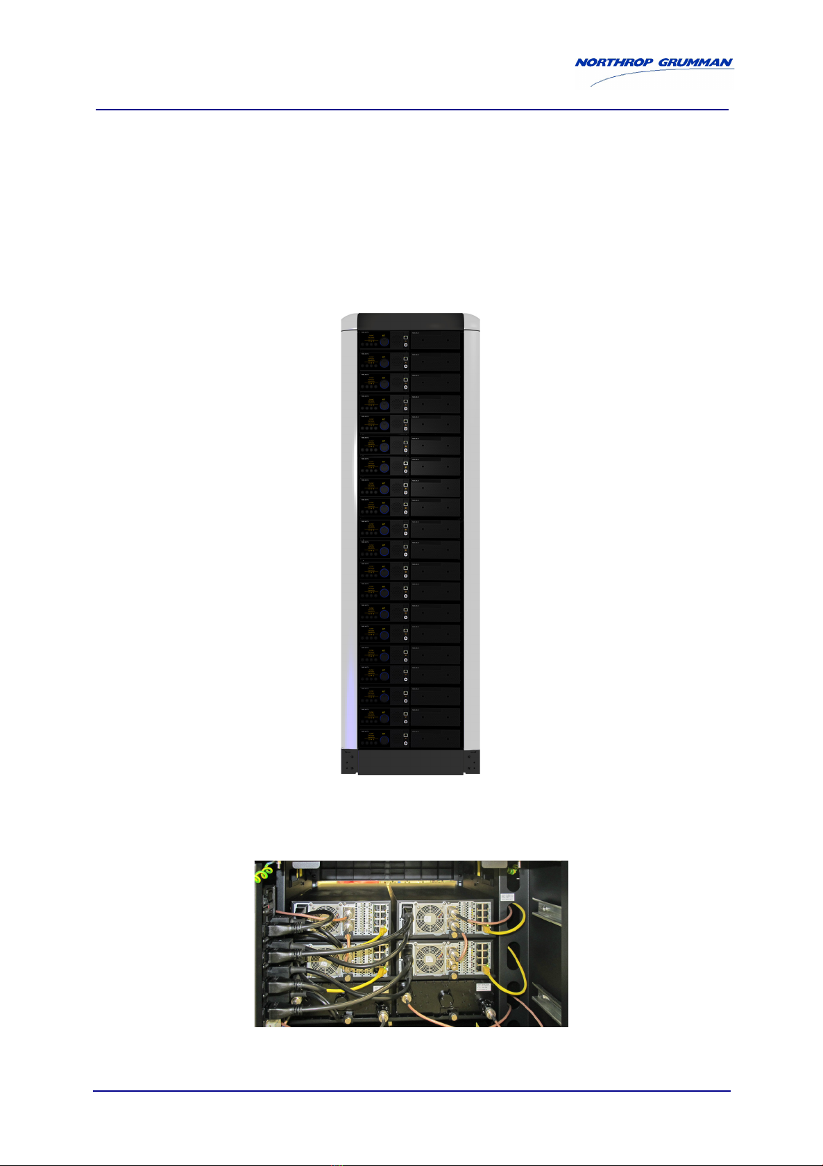
1.1.2 Park Air C4 cabinet installation
The Park Air T6 radios and Park Air Z4 filters are specifically designed to fit the Park Air C4 cabinet. The C4 cabinet
(40U) can accommodate up to 40 T6 radios or Z4 filters.
The Park Air C4 options:
40U or 30U capacity.
Typical T6 radio and Z4 filter installation:
Installation details are shown in 3.2 Park Air C4 cabinet installation.

T6-D-USER-RV-EN Page 1-3 Overview
© Park Air Systems Ltd 2015
1.2 Park Air T6-RV
The product codes and product names of the radio, options, accessories and documentation for the T6-RV radio.
1.2.1 Park Air T6-RV product code
1.2.2 Park Air T6-RV options
1.2.3 Park Air T6-RV accessories
1.2.4 Park Air T6-RV documentation
Product code Product name Notes
T6-RV VHF receiver
Product code Product name Notes
T6-O-112-137 112 MHz to 137 MHz frequency range for T6 radios
T6-O-112-156 112 MHz to 156 MHz frequency range for T6 radios
T6-O-118-137 118 MHz to 137 MHz frequency range for T6 radios
T6-O-118-156 118 MHz to 156 MHz frequency range for T6 radios
T6-O-AMA ACARS waveform for T6 radios
T6-O-AMV AM-voice waveform for T6 radios Includes VoIP in accordance with all editions of
ED-137
T6-O-AMW AM-wideband waveform for T6 radios
T6-O-SCT Simultaneous Call Transmission Detection algorithm for T6
radios
T6-O-VDLM2 VDL-Mode 2 waveform for T6 radios
Product code Product name Notes
T6-A-CK Connector kit for T6 radios
Includes AC mains power lead, DC power
connector, N-type connector and RJ45 to RJ45
patch cable
T6-A-CMA1 Cooper B-Line cabinet mounting adaptor for one or two T6
radios
Product code Product name Notes
T6-D-USER-RV-EN User documentation for T6-RV in English

T6-D-USER-RV-EN Page 1-4 Overview
© Park Air Systems Ltd 2015
Intentionally Blank

T6-D-USER-RV-EN Page 2-1 Description
© Park Air Systems Ltd 2015
2 Description
The T6-RV interfaces are shown in this section.
2.1 Front panel interfaces
Control Notes
On/off switch Front panel on/off of the radio See 2.1.1 On/off switch
Display Parameter fields and soft function icons See 2.1.2 Display
Soft function keys See 2.1.3 Soft function keys on page 2-2
Busy indicators See 2.1.4 Busy indicators on page 2-3
Rotary/push switch Volume control, display control and selection See 2.1.5 Rotary/push switch on page 2-3
Status indicator BIT and radio inhibit status See 2.1.6 Status indicator on page 2-3
Connector Connectivity
LAN 3 10/100 Mbps, RJ45
See LAN 3 connector on page 6-1
Reference
frequency
monitor
20 MHz high impedance output,
SMB
See Reference frequency monitor connector on page 6-1
Microphone/
headset Receive audio, LEMO™
See Microphone/headset connector on page 6-1
Busy indicators Rotary/push switch
Display
On/off switch
Soft function keys Status indicator Loudspeaker
Microphone/headset
connector
Reference frequency
monitor connector
LAN 3 connector
Frequency counter
.
Headset
Laptop

T6-D-USER-RV-EN Page 2-2 Description
© Park Air Systems Ltd 2015
2.1.1 On/off switch
Note:
This action symbol is used in the document.
2.1.2 Display
This is a high resolution OLED display.
2.1.3 Soft function keys
There are three soft function keys below the display. Soft function icons are displayed above the keys and shown
in 2.1.3.1 Soft function icons.
2.1.3.1 Soft function icons
Control Notes
On/off switch The power cord is the power disconnect device.
118.000 MHz
AM Voice
Soft function icon Function Notes
Home
Menu
Squelch override The busy indicator illuminates
Receive inhibited The soft function key is disabled
Back Previous menu
Left or right Moves the cursor
Enter Same as when the rotary/push switch is pushed
Save
Note:
In the example, two parameter
fields are shown and one is blank.
Up to three parameter fields can
be shown or blank.
The display brightness lessens
after 24 hours
Parameter fields
Soft function key icons

T6-D-USER-RV-EN Page 2-3 Description
© Park Air Systems Ltd 2015
2.1.4 Busy indicators
2.1.5 Rotary/push switch
Note:
These action symbols are used in the document.
2.1.6 Status indicator
The Status indicator is around the rotary/push switch.
Note:
These action symbols are used in the document.
Busy indicator Function Notes
The radio receives The busy indicator illuminates amber
Action Notes
Adjust the rotary/push switch Changes selected volume setting.
Changes the display menu
Push the rotary/push switch Selects.
Saves settings
Status indicator Action Notes
Illuminates
blue
BIT status is Full Service.
Radio is not inhibited
Illuminates
amber BIT status is Reduced Service
Illuminates red BIT status is No Service
or Reduced Service is made No Service by the user

T6-D-USER-RV-EN Page 2-4 Description
© Park Air Systems Ltd 2015
2.2 Rear panel connectors
Each connector type is shown in the table below and associated connection cable colour codes.
Connector Connector type Cable Notes
DC input Saf-D-Grid chassis plug See DC input connector on page 6-6
AC input IEC-C14 chassis plug See AC input connector on page 6-6
Antenna N-type socket See ANTENNA connector on page 6-7
RF LINK N-type socket See RF LINK connector on page 6-7
Earth stud
connector M5 thread See Earth stud connector on page 6-6
AUDIO RJ45 socket Red See AUDIO connector on page 6-2
LINK RJ45 socket Orange See LINK connector on page 6-2
FAC RJ45 socket Yellow See FAC (facilities) connector on page 6-3
E1 RJ45 socket Blue See E1 connector on page 6-4
FILTER RJ45 socket Purple See FILTER connector on page 6-4
LAN 1RJ45socket Grey See LAN 1 connector on page 6-5
LAN 2 RJ45 socket Grey See LAN 2 connector on page 6-5
LAN 1 connector LAN 2 connector
FILTER connector
E1 connector
AUDIO connector
Not used
FAC (facilities) connector
LINK
connector
ANTENNA connector
RF LINK connector
DC input
AC input
Earth stud connector
Other manuals for Park Air T6-RV
1
This manual suits for next models
1
Table of contents
Other NORTHROP GRUMMAN Receiver manuals


