5.3 Crosshair
Level the instrument. Observe the horizontal hair while moving the telescope left and right, making sure the
horizontal hair stays on a point. If it does not remain on point, the diaphragm should be rotated until it will stand
this test.
Loosen the screws holding crosshair ring and gently tap on the screws until horizontal hair is in position to remain
on the same point as telescope is moved left and right.
NOTE: The above adjustment may change instrument calibration.
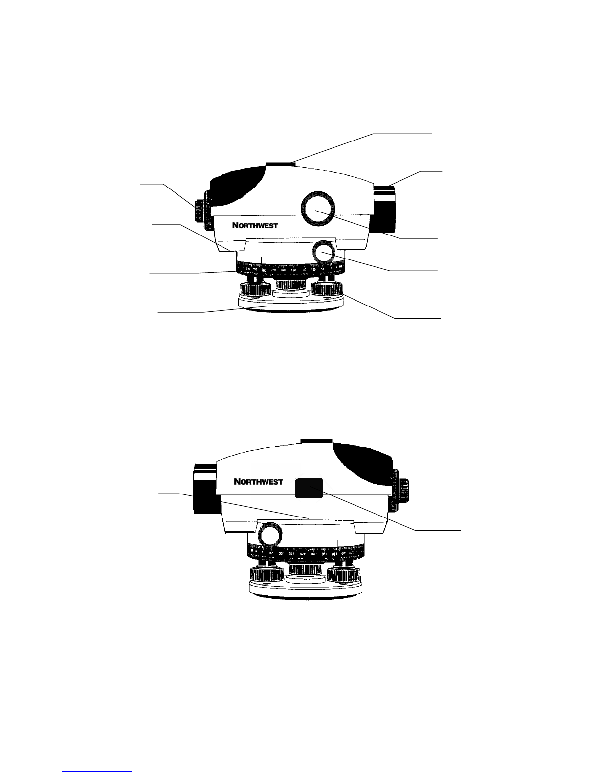
5.4 Adjusting the Compensator
The compensator in your Northwest Automatic Level is a high accuracy, wire hung magnetically dampened optical
system, which should not be adjusted or repaired in the field. If you feel the compensator is not operating properly,
the following test should be conducted:
1) Set up and level your instrument as usual. Position the telescope directly over a leveling screw. Focus the
telescope on a distant reference point. Observe the intersection of the crosshairs on the reference point. Then turn
the leveling screw, which is directly under the telescope. When doing this, make sure not to let the bubble out off
circle. If the line of sight changes from the original setting, it shows that the compensator is not working properly and
should be adjusted by the factory or a qualified service technician.
2) Shake the instrument gently. If there is no movement sound heard or nonappearance of movement within the
telescope, it may indicate that the compensator is jammed. For further checking, level the instrument, focus well, sight
through the telescope and line up the crosshair on a mark. And then tap the tripod firmly while not changing its
position or height. If the crosshair did not shift and back to its original mark, the compensator is considered possibly
damaged and need service.
3) The compensator lock is always the best method to test the compensator. Tap the compensator lock button to test
compensator.
5.5 Repair Shop Adjustments
The following adjustments should be conducted only by a qualified service technician.
1. Fitting of centers
2. Fitting of focusing slides
3. Compensator adjustments
Call NORTHWEST INSTRUMENT, INC. to find the service centers near you.