Northwestern Bell Easy Touch 28507 User manual

112189A-1
OWNER’S MANUAL # 28507 ver. 12189A-1
PAGE # 1English Version
IMPORTANT SERVICE INFORMATION
Read this manual before attempting to setup or use this instrument. It contains important
information regarding safe installation and use. Keep this manual for future reference.
Also save the carton, packing andproof of purchaseto simplify and accelerate any needed
action. If you need assistance or service, call (800) 888-8990 between 8:00 a.m. and 4:30 p.m.
Pacific Standard Time, Monday through Friday. You can also visit our web site at
http://www.nwbphones .com for technical support and information on our other products.
WARNING
To prevent fire or shock hazard, do not expose this product to rain or any type of excess
moisture. If accidentally dropped into water, the AC power cord should immediately be
unplugged from the wall.
THIS SYMBOL IS INTENDED TO ALERT THE USER OF
THE PRESENCE OF IMPORTANT OPERATING AND
MAINTENANCE (SERVICING) INSTRUCTIONS IN THE
OWNER'S MANUAL.
Easy Touch® 28507
Clock Telephone
CARTON CONTENTS
•Base & Handset
•Handset Cord
•Telephone Line Cord
•User’s Manual
•Warranty Card
•Memory Index Card
•Accessory Order Form
THIS SYMBOL IS INTENDED TO ALERT THE USER OF
THE PRESENCE OF UNINSULATEDDANGEROUS
VOLATAGE” WITHIN THE PRODUCT’S ENCLOSURE THAT
MAY BE OF SUFFICIENT MAGNTUDE TO CONSTITUTE A
RISK OF ELECTRIC SHOCK TO PERSONS.

12189A-1 2
OWNER’S MANUAL # 28507 ver. 12189A-1
PAGE # 2English Version
IMPORTANT SAFEGUARDS
When using your telephone equipment,
basic safety precautions should always
be followed to reduce the risk of fire,
electric shock, and injury to persons,
including the following:
1. Read and understand all
instructions.
2. Follow all warnings and instructions
marked on the product.
3. Unplug this product from the wall
outlet
Before cleaning. Do not use liquid
Cleaners or aerosol cleaners. Use a
Damp cloth for cleaning.
INSTALLATION:
1. Do not use this product near water,
for example, near a bathtub, wash
bowl, kitchen sink, or laundry tub, in
a wet basement or near a swimming
pool.
2. Do not place this product on an
unstable cart, stand, or table. The
product may fall, causing serious
damage to the product.
3. Slots and openings in the cabinet
and the back or bottom are provided
for ventilation, to protect it from
overheating. These openings
should never be blocked or covered.
The openings should never be
blocked by placing the product on
the bed, sofa, rug, or other similar
surface.
4. This product should never be
placed near or over a radiator or heat
register.
5. This product should not be placed
in a built-in installation unless
proper ventilation is provided.
6. If this telephone equipment can be
mounted to a wall, it should only
mounted according to the
manufacturer
USE
1. This product should be operated
only from the type of power source
indicated on the marking label. If
you are not sure of the type of
power supply to your home, consult
your dealer or local Power Company.
2. Do not allow anything to rest on the
power cord. Do not locate this
product where the cord will be
abused by persons walking on it.
3. Do not defeat the polarization and
grounding features of the AC power
cord.
4. Ensure that the AC wall outlet holds
the AC power cord securely and
firmly. If the AC wall outlet is loose,
contact an electrician to replace the
unsafe AC receptacle.
5. When the product is to be left
unused for a long period of time,
unplug the power cord from the AC
outlet by grapsing the plug , not the
cord.
6. Never push objects of any kind into
This product through cabinet slots
as They may touch dangerous voltage
points or short out parts that could
result in a Risk of fire or electronic
shock. Never Spill liquid of any kind
on the product.
7. Clean this product only as
recommended by the manufacturer.
SERVICE:
Unplug this product from the wall
outlet
And refer servicing to qualified
service
Personnel under the following
Conditions:
1. When the power supplies cord
or plug is damaged orfrayed.

12189A-1 3
OWNER’S MANUAL # 28507 ver. 12189A-1
PAGE # 3English Version
2. If liquid has been spilled into
the product.
3. If the product has been
exposed to rain or water.
4. If the product does not operate
normally by following the
operating instructions. Adjust
only those controls that are
covered by the operating
instructions. Improper
adjustments of other controls
may result in damage and will
often require extensive work
by a qualified technician to
restore the product to normal
operation.
5. If the product has been
dropped or the cabinet has
been damaged.
6. If the product exhibits a
distinctive change in
performance.
7. Avoid using a telephone (other than
a cordless type) during an electrical
storm. There may be a remote risk of
electric shock from lightning.
8. Do not use the telephone to report a
gas leak in the vicinity of the leak.
9. The user should not attempt to
service the product beyond that
described in the operating
instructions. All others servicing
should be referred to qualified
service personnel only.
ANTENNAS
Outdoor Antenna Grounding—If an
outdoorantenna or cable system is
installed, follow these precautions:
An outdoor antenna system should not
be located in the vicinity of overhead
power lines or other electric light or
power circuits, or where it can come in
contact with such power lines or circuits.
WHEN INSTALLING AN OUTDOOR
ANTENNA SYSTEM, EXTREME CARE
SHOULD BE TAKEN TO KEEP FROM
CONTACTING SUCH POWER LINES
OR CIRCUITS AS CONTACT WITH
THEM IS ALMOST INVARIABLY
FATAL.
Be sure that the antenna system is
grounded so as to provide some
protection against voltage surges and
built-up static charges. Section 810 of
the National Electric Code(NEC)
provides information with respect to
proper grounding of the lead-in wire to
an antenna discharge unit, size of
grounding conductors, location of
antenna-discharge unit, connection to
grounding electrodes, and requirements
for the grounding electrode.
MAINTENANCE
1. Use a damp cloth to clean the plastic
cabinet. A mild soap will help to
remove grease or oil. Never use
polish, solvents, abrasives or strong
detergents since these can damage
the finish.
2. Your phone should be situated away
from heat sources such as radiators,
heaters, stoves or any other
appliance that produces heat.
ANTENNA GROUNDING ACCORDING

12189A-1 4
OWNER’S MANUAL # 28507 ver. 12189A-1
PAGE # 4English Version
TO NATIONAL ELECTRICAL CODE
lNEC National Electrical Code
CAUTION
To reduce the risk of fire or injury to
persons, read and follow these
instructions:
1. Use only the batteries specified in
this manual.
2. Do not dispose of the batteries in a
fire. The cell may explode. Check
with local codes for possible special
disposal instructions.
3. Do not open or mutilate the
batteries. Released electrolyte is
corrosive and may cause damage to
the eyes or skin. It may be toxic if
swallowed.
4. Exercise care in handling the
batteries in order not to short the
batteries with conducting material
such as rings, bracelets and keys.
The batteries or conductor may
overheat and cause burns.
5. Do not attempt to recharge the
batteries provided with or identified
for use with this product. The
batteries may leak corrosive explode.
6. Do not attempt to rejuvenate the
batteries provided with or identified
for use with this product by heating
them. Sudden release of the battery
electrolyte may occur causing burn
or irritation to eyes or skin.
7. When inserting the batteries into
this product, the proper polarity or
direction must be observed. Reverse
insertion of batteries can cause
charging, and that may result in
leakage or explosion.
8. Remove the batteries from this
product if the product will not be
used for a long period of time
(several months or more) since
during this time they could leak in
the product.
9. Discard the “dead” batteries as soon
as possible since “dead” batteries
are more likely to leak in a product.
10. Do not store this product, or the
batteries provided with or identified
for use with this product, in high-
temperature areas. Batteries that are
stored in a freezer or refrigerator for
the purpose of extending shelf life
should be stabilized at room
temperature prior to use after cold
storage.
ANTENNA
LEAD IN
WIRE
GROUND
CLAMP
ELECTRIC
SERVICE
EQUIPMENT
ANTENNA
DISCHAREG UNIT
(NEC SECTION 810-
20)
GROUNDING CONDUCTORS
(NEC SECTION 810-20)
GROUND CLAMPS
POWER SERVICE GROUNDING
ELECTRODE SYSTEM
(NEC ART 250, PART H)
CAUTION: TO REDUCE THE RISK OF ELECTRIC
SHOCK, DO NOT REMOVE COVER (OR BACK).NO
USER SERVICEABLE PARTS INSIDE. REFER
SERVICING OT QUALIFIED SERVICE PERSONNEL.
CAUTION
RISK OF ELECTRIC
SHOCK

12189A-1 5
OWNER’S MANUAL # 28507 ver. 12189A-1
PAGE # 5English Version
11. Always disconnect all telephone
line cords from the wall modular
jacks before installing or replacing
batteries.
FCC NOTICE
The FCC requires that you be advised of
certain requirements involving the use of
this telephone.
1. This unit is Hearing Aid Compatible.
2. This equipment complies with Part
68 of the FCC rules. On the bottom
of this equipment is a label that
contains, among other information,
the FCC registration number and
Ringer Equivalence Number (REN)
for this equipment. If requested,
provide this information to your
telephone company.
3. The REN is useful to determine the
quantity of devices you may
connect to your telephone line and
still have all of those devices ring
when your number is called. In
most, but not all areas, the sum of
the RENs of all devices should not
exceed five (5.0). To be certain of the
number of devices you may connect
to your line, as determined by the
REN, you should call your local
telephone company to determine the
maximum REN for your calling area.
4. If your telephone causes harm to the
telephone network, the telephone
company may discontinue your
service temporarily. If possible, they
will notify you in advance. But if
advance notice is not practical, you
will be notified as soon as possible.
You will be advised of your right to
file a complaint with the FCC.
5. Your telephone company may make
changes to its facilities, equipment,
operations or procedures that could
affect the proper operation of your
equipment. If they do, you will be
given advance notice so as to give
you an opportunity to maintain
uninterrupted service If you
experience trouble with the
telephone, please contact VTC
Service & Manufacturing Co., Inc at
(800)888-8990 or write to: VTC
Customer. Service ,16988 Gale Ave.,
City of Industry, CA 91745 for
repair/warranty information. The
Telephone Company may ask you to
disconnect this equipment from the
network until the problem has been
corrected or you are sure that the
equipment is not malfunctioning.
6. This equipment may not be used on
coin service provided by the
Telephone Company. Connection to
party lines is subject to statetariffs.
(Contact your state public utility
commission or corporation
commission for information.)
This device complies with Part 15 of the FCC Rules. Operation is subject to
The following two condition: (1) This device may not cause harmful
Interference, and (2) this device must accept any interference received,
Including interference that may cause undesired operation. Privacy of
Communications may not be insured when using this phone.
612189A-1
OWNER’S MANUAL # 28507 ver. 12189A-1
PAGE # 6English Version
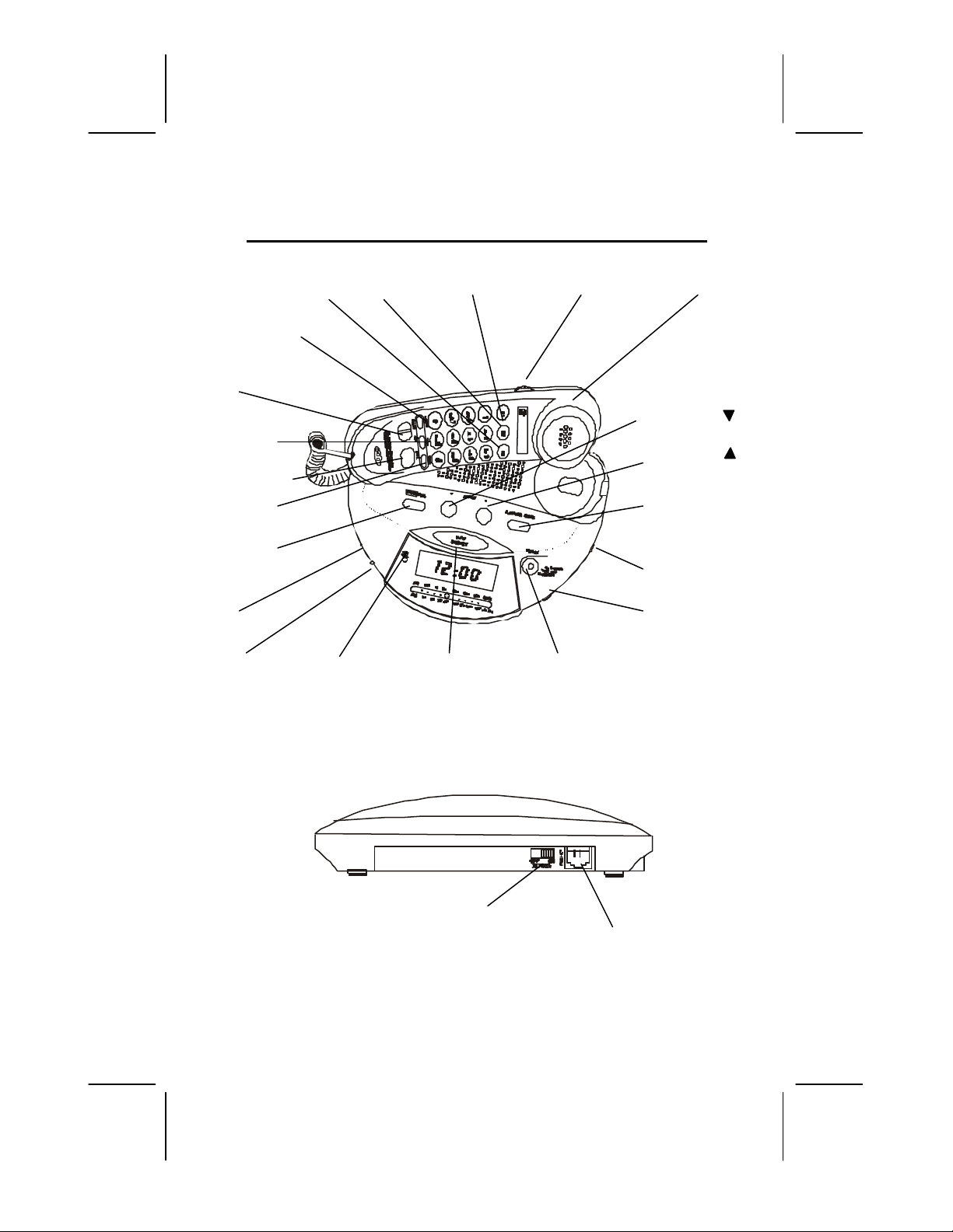
EASYTOUCH®28507 CONTROLS DIAGRAM
OFF/ON
RINGER
Switch
Telephone
LINE JACK
Handset
E3 Button E2 Button E1 Button Volume Control
MEMORY Button
PULSE/TONE Switch
FLASH Button
REDIAL Button
STORE Button
ENTER/DEL
Button
ON/OFF/AUTO/
BUZZ
AM/FM NEW CALL SLEEP/SNOOZE OPTION
Switch LED Indicator Button Button
Review UP
Review DN
Call Back/
Alarm Mode
TUNING Switch
Volume Switch

712189A-1
OWNER’S MANUAL # 28507 ver. 12189A-1
PAGE # 7English Version
DESCRIPTIONS
Caller ID Controls:
Alphanumeric LCD panel-A three-
line,liquid crystal display (LCD) panel
which displays the following
information:
lCaller Name/ Phone Number
lTime/ Date of Call
lRepeat Call
lCall Summary
lBlocked Calls
lOut of Area Calls
lMessage Waiting
lReal Time Clock
lCall Timer
lIN USE Indication
lLow Battery Indication
Call Back Button -The EasyTouch®28507
can automatically call back the phone
number of a person who has called you on
the telephone.
DELETE Button -Deletes individual call
records or all call records.
Option Button—Allows you to change the
format of display of the phone number.
Review UP/DOWN Buttons -Allows
you to view the call history list in either
direction.
NEW Call LED/ Message Waiting
Indicator -Flashes to indicate that new
calls have been received or a Message
Waiting signal was sent by your local
phone company.
NOTES:
•This LED will turn off once you
have reviewed all your call
records and Message Waiting
messages.
•Message Waiting is an optional
service provided by your local
phone company.
Telephone Controls:
Emergency Buttons (E1, E2, & E3) –
Allows one-touch dialing from any one of
the three emergency numbers.
FLASH Button –Hang up the phone
momentarily, allowing you to access
custom calling features provided by your
local telephone company.
MEMORY Button – Used for retrieving
phone numbers from the 10 memory
locations.
REDIAL Button – Used to automatically
dial the last phone number dialed. Pressing
this button in the dialing sequence will
inserts a 4 seconds pause between dialed
numbers.(for use in PABX or long distance
services)
Handset Volume Nor/Med/High Switch—
Allows you to select handset receiver
either Normal-Medium or High Volume.
Store Button—Used to program phone
numbers in memory.
Ringer OFF/ON Hookswitch—A Switch
located on the rear of the base unit, which
is used for turning the ringer OFF or ON.
TONE/PULSE Switch – Located on the
handset. This allows you to use your
phone with pulse or tone service.
812189A-1
OWNER’S MANUAL # 28507 ver. 12189A-1
PAGE # 8English Version
Clock Alarm /Radio Controls:
Option Button Uses:
Alarm Set---Used this button to program
the desired alarm time. Press once to OFF
the alarm.
TIME SET Button – Used to set the
current time/date.
(On/Off/Auto/Buzz) Switch
On/Off—Turn On/Off the radio.
Auto—Alarm/Radio Accessible.
Buzz—Alarm beep setting.
SLEEP/SNOOZE Button – Pressing this
button temporarily halts the alarm from
sounding when the alarm rings.
This button also used to setradio to off
automatically.
Volume Control—Allows you to adjust
the loudness of the speaker by rotating the
knob located on the right side edge of the
base unit.
Tuning—Allows you to select the desired
AM/FM Radio station.
AM/FM Switch—Allows you to select
either AM or FM band Radio.
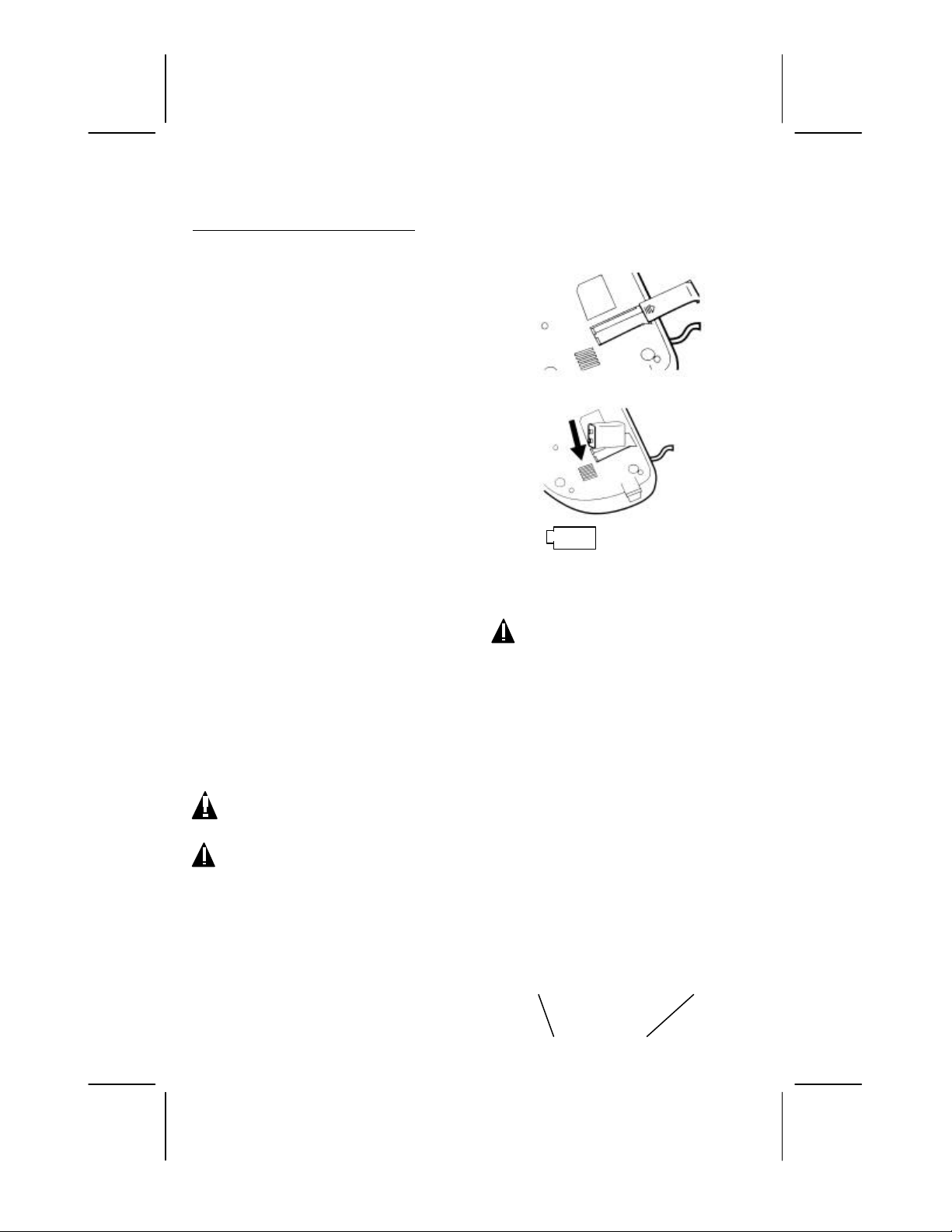
INSTALLATION
Installing the Backup Batteries
CAUTION: Disconnect the
telephone line from the telephone wall
modular jack before replacing batteries.
1. Remove the battery compartment
cover of the 28507.
2. Install a new 9-Volt back up battery
(not supplied), alkaline is
recommended , into the battery
compartment of the base unit. Ensure
that the polarities as shown on figure
1 are followed.
3. Replace the battery compartment
cover.
NOTE: 1) Replace the batteries as soon
as possible when the LOW Battery
symbol appears on the LCD
panel.
2) Battery is used only for keeping memory
during power failure.
CAUTION: To reduce the risk of
electric shock do not remove cover (or
back). No user serviceable parts inside.
Refer servicing to qualified personnel.
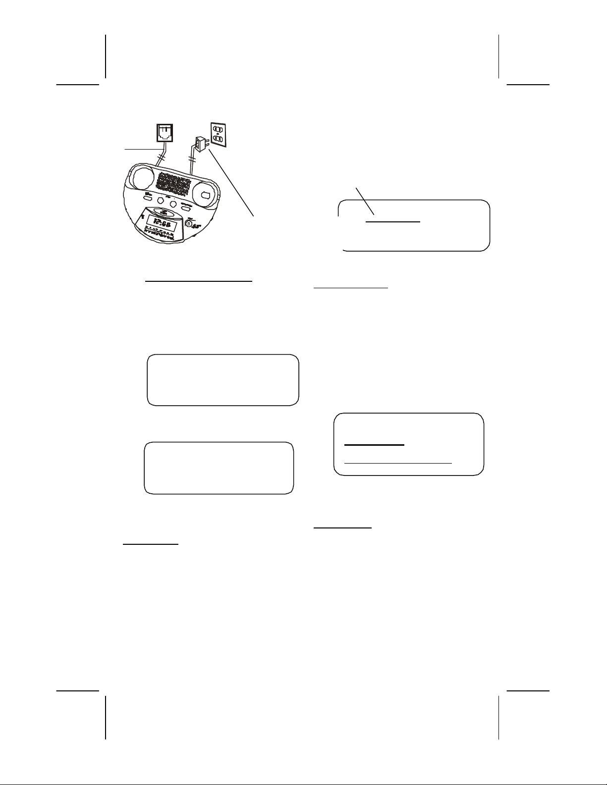
Select a location near a modular telephone
jack and an AC outlet.
Desktop Connection
1. Plug the AC power code of the unit
into a 110V AC wall outlet.
2. Insert one end of the telephone line
cord into the LINE jack on the rear of
the 28507.
3. Plug the other end of the telephone
line cord into the modular telephone
jack located on yourwall.
Telephone Jack Wall Outlet
Line
Cord
LOW
912189A-1
OWNER’S MANUAL # 28507 ver. 12189A-1
PAGE # 9English Version
GETTING STARTED
Caller ID Initial Setup:
After the battery installation and
telephone line connection the
display will show:
This will appear first
This will appear second
Set Language
1. Press the Review UP or DOWN
button to select the desired language.
E= ENGLISH
F= FRENCH
S= SPANISH
2. Once the desired language is selected
, press the ENTER/DEL button to
confirm selection.
3. Then the display will change to area
code setting.
NOTE: If no activate buttons are
pressed for 15 second, the LCD
display will automatically change to
STANDBY/MODE.
The first digit will be blinking
Area Cord Setting
1. Press the Review UPor DOWN button
to select the first digit area code
number.
2. Press the Delete button to confirm.
3. Repeat step 1 and step 2 above to set
the second and third digit.
4. Once the correct area code is shown
on the display, press the ENTER/DEL
button to confirm, then the display
will change to TIME/DATE setting.
The hour icon will be blinking
Set Time/Date
1. Press the UP or DOWN
button to set the current hour.
2. Press the ENTER/DEL button to
shift to the minute setting.
3. Repeat steps 1 and 2 above to set
MINUTE, MONTH and DATE.
4. Once the correct TIME/ DATE is
shown on the display, press the
ENTER/DEL button to end the
setting. Then the display will
E F S
SET LANGUAGE
12:00PM 1/01
SET TIME/DATE
80-CALLS
CLKNU VER XXX
0 0 0
SET AREA CODE
AC Power Plug

10 12189A-1
OWNER’S MANUAL # 28507 ver. 12189A-1
PAGE # 10 English Version
change to show the normal
status.
Changing The Language Mode and
AREA CODE
1. Press and hold the DELETE button
then press UP button.
2. The LCD display will show:
Follow forenamed steps described
In section of “SETTING THE
LANGUAGE MODE AND
AREA CODE”
NOTE: To change the current time,
follow steps described in section “
SETTING THE TIME/DATE” of the
Clock/Alarm operaton.
CALLER ID OPERATION
IMPORTANT: Subscription to Caller
ID service from your local phone
company is required before initial
use.
Automatic Time/Date
Stamping
The time/date stamp for all
incoming calls will be recorded and
stored automatically each time a call
is received.
Receiving Caller ID Information
When a phone call comes in, this
unit will capture the Caller ID date
sent from the phone company in
between the first and second ring,
the LCD panel will display the Caller
ID information such as name (if
available), phone number (if
available), date and time of call. All
incoming phone call records are
stored in the order in which they are
received.
NOTE:
lThe Caller ID information may
not be displayed if you pick up
the phone before the second
ring. Make sure that the Call
Identifier Delivery (CID) service
is being
provided on your telephone
line by your local phone
company. When CID data is sent, the
unit will automatically
capture and display the
transmission from the phone
company.
lIf a caller’s area code does not
match with area code you
entered during set up, it will
automatically add long distance
code “1” along with the area
code and phone number.
Message Waiting
If you have Message Waiting
messages stored in the mailbox
(provided by your local phone
company), upon receiving the
message waiting, the
“MESSAGE WAITING” will be
displayed on the LCD panel for a
short time and the NEW CALL LED
indicator will start to blink. the
12:00PM 1/01
TOTAL00 NEW 00
E F S
SET LANGUAGE

11 12189A-1
OWNER’S MANUAL # 28507 ver. 12189A-1
PAGE # 11 English Version
“MSG” icon will flash on the left
side of the LCD panel.
Once you have retrieved the
message, the “MSG” icon will
disappear from the panel and the
NEW CALL LED Indicator will turn
off after all new call messages have
been reviewed. “Message Waiting
Indication” is not yet supported in all
areas. In these areas message waiting
is usually indicated by a stutter dial
tone. Please consult with your local
telephone service provider for
information regarding your message
waiting services.
Clear Message Waiting Indicator
Press and hold the DELETE button
followed by DOWN
button to clear the message
waiting.
Reviewing Call Records
If you have received new calls, the
NEW CALL LED indicator will blink
and LCD panel will display the total
number of calls and new calls when
this unit is in idle mode.
Using the Review UP and
Review DOWN Button
Press the Review UP or Review
Down button to browse through the
call history list.
NOTE: “END OF LIST” will show
on the third line of display indicating
the end of the call history list is
reached while using the Review UP
or DOWN button.
Erasing Call Records
The DELETE button can be used to
remove previously reviewed call
records.
To Delete a Single Call Record:
1. Press either one of the UP or DOWN
buttons to display the call record to
be deleted.
2. Quickly tap the DELETE button twice.
3. After you have deleted the call record,
the display will show the next Caller
ID record.
To Delete All Call Records:
1. Press either the Review Up or Down
button once to enter the call history
list.
2. Press and hold the DELETE button for
five seconds.
3. When the message “NO CALL”
appears on the LCD panel, it indicates
that all call records have been deleted
from the call record memory.
NOTE: The DELETE button is
disabled temporarily when the LCD
panel shows “END OF LIST”.
CALL BACK Button
lPress the review DOWN or UP
button to select phone number to be
called. Press the call back button, the
messagePick Up Phone” will
appear to the LCD screen. Lift the
handset and the number you selected
will be dialed automatically.
lIf you already picked up the
handset, you may select the number to
be dialed by reviewing the stored
number, press the Call Back button
,then the number you selected will
be dialed automatically.
OPTION Button
During reviewing call records, press the
Option Button to change the format of
displayed numbers. The available format
as follows:
7 Numbers—7 Digit Phone Number
10 Numbers—3 Digit Area Code + 7 Digit
Phone Number

12 12189A-1
OWNER’S MANUAL # 28507 ver. 12189A-1
PAGE # 12 English Version
11 Numbers—Long Distance Code “1” + 3
Digit Area Code + 7 Digit Phone Number.
Note: If the caller’s area code does not
match the area code you set in 28507,
11numbers will appear on the display.
TELEPHONE OPERATION
Pulse/Tone Dialing
lIf your home is equipped with touch-
tone dialing service, set the
PULSE/TONE switch to TONE
position.
lIf you have a pulse (rotary) dialing
service, set the PULSE/TONE switch
to PULSE position.
Pulse Tone (Mixed Mode) Dialing
lIf you only have pulse (rotary dialing)
service in your area and want to
access touch-tone service, set the
Pulse/Tone switch to the Pulse
position. Dial the desired number and
when tone desired number and when
tone signals are required press the
TONE (*) button once. Subsequent
digits will be dialed in tone mode
when handset is returned on-hook.
Ringer Switch
If you do not want the ringer to sound. Set
the RINGER ON/OFF switch to OFF
position. You can still make calls. And you
can answer calls if you hear another phone
on the same phone line ring.
Placing a call
Lift the handset and listen for a dial tone.
Dial the desired phone number.
Receiving a Call
When the phone rings lift the handset and
start conversation with the caller.
Ending a Call
Upon completion of a call, return the
handset in its cradle, or depress the hook
switch button to restore a dial tone if you
want to make another call.
Last Number Redial
1. Pick up the handset and listen for a
dial tone.
2. Press the REDIAL button. The phone
number dialed last will be dialed out
automatically. The 28507 can redial up
to 32 digits.
NOTE: If you get a busy signal after
dialing a number, just press REDIAL. Press
“REDIAL” Button to insert 4 seconds
pause while dialing in a PABX or long
distance services.
FLASH
Many special telephone services require a
switch hook signal. When you press
FLASH, your phone produces an
electronic switch hook signal that is more
accurate and more
convenient than using the phone’s switch
hook.
Example: If you subscribe to Call Waiting,
you can press FLASH to put your current
call on hold and take the incoming call.
Pressing the FLASH button again will
return you to the first call. You can
repeatedly press FLASH to alternate
between the two calls.
To Program 3 Emergency Numbers
1. Lift HANDSET. Listen for dial tone.
2. Press and release STORE button.
3. Enter the number to be stored. (The
telephone will not dial out.)
4. Press and release STORE button.

13 12189A-1
OWNER’S MANUAL # 28507 ver. 12189A-1
PAGE # 13 English Version
5. Press E1, E2 or E3 button respectively
for each of the three emergency
numbers you wish to store.
6. Replace HANDSET to BASE.
IMPORTANT: When programming
emergency numbers and/or making test
calls to emergency numbers:
1. Remain on the line and briefly explain
to the dispatcher the reason for a call
before hanging up.
2. Perform such activities in off-peak
hours. Such as early morning or late
evening.
NOTE: You can write the programmed
memory location and description on the
memory Index Card provided.
Dial an Emergency Number
1. Lift HANDSET, Listen for dial tone.
2. Press the Emergency button (E1, E2,
or E3) corresponding to the number
you wish to call.
To Program 10 Frequently Called
Numbers
1. Lift HANDSET. Listen for dial tone.
2. Press and release STORE button.
3. Enter the number to be store. (The
telephone will not dial out.)
4. Press and release STORE button.
5. Press a number (0-9) on the keypad.
Where you want the number stored.
6. Replace HANDSET to BASE.
7. Repeat step 1-6 to store additional
numbers.
NOTE: You can write the programmed
memory location and description on the
Memory Index Card provided.
Dial a Number from Memory Location (0-
9)
1. Lift HANDSET. Listen or dial tone.
2. Press the Memory button
3. Press the desired Memory Location
button (0-9).
CLOCK/ALARM OPERATION
Setting the Time/Date
1. Press and hold the TIME set (option)
button until “SET TIME/DATE” appear
on the LCD screen .
2. Follow forenamed steps described in
section “ SET TIME/DATE”
To Set the Alarm Mode
1. Press the “ Alarm Mode” button, the
LCD will display and flash the current
program.
2. Press the Review UP or DOWN
button to select the following mode
Alarm1 On
Alarm 2 On
Alarm1/Alarm 2 On
Alarm/Off
3. Press “Enter/Del” button after you
selected the desired mode.
Alarm
Setting Alarm 1/2
1. At standby(On-Hook) mode, press
the “OPTION” (AL. SET)1 Button.
The message “SET ALARM1 TIME”
will appear on the LCD display, hour
is blinking.
2. Press Review UP or DOWN button to
set the desired hour time.
3. Press Enter/DEL button to shift to
minute setting.
4. Press review UP or DOWN button to
set the desired minute.
5. Press Enter/DEL button to confirm
and the LCD display will change to
Alarm2 setting.
6. Repeat steps 2-5 to set Alarm2.
NOTE: If you want to set alarm 1 only, and
alarm2 is displayed, press Enter/Del

14 12189A-1
OWNER’S MANUAL # 28507 ver. 12189A-1
PAGE # 14 English Version
repeatedly until the LCD displays “
STANDBY MODE”
Turning Off the Alarm
Press the OPTION(AL.OFF) button, the
LCD panel will display “ALARM OFF”
Checking the Alarm—At standby( On-
Hook) mode, press the AL Set Button
quickly to view the alarm time setting.
Press Enter/Del button repeatedly until the
“STANDBY MODE” appear on the LCD.
Sleep/Snooze
Press the button temporarily halts the
alarm from sounding when the alarm rings.
After about nine minutes. The alarm will
resume sounding again. Each press of this
button will resume sounding 9 minutes
cater to “Turn Off” the alarm. Press alarm
OPTION (SET/ OFF) button.
Radio Auto-Off Setting
1. Press the sleep/snooze button”
0:59/SLEEP ON” will appear on the LCD
Display.
2. Press continuously to set the desired
time from 1~59 minutes whrein your
radio will automatically sent to “OFF”
3. Turn the”ON/OFF/AUTO/BUZZ” switch
to buzz mode.
TROUBLE SHOOTING
CALLER ID SYSTEM TROUBLESHOOTING TABLE
SYMPTOM SOLUTION
The Caller ID LCD
panel is blank
lCheck the telephone line cord connections.
lCheck the batteries for proper installation.
The Caller ID LCD
panel does not
show the caller’s
name and/or
phone number
lThe Caller ID unit will not function until you have Caller ID
service provided by your local phone company. Call your local
phone company to have Caller ID installed on your telephone
line.
lCheck your telephone line connections. Make sure all
connections are secure and connected.
l
If you picked up the phone before the second ring, the caller
TIME DATE
TOATALXX NEWXX

15 12189A-1
OWNER’S MANUAL # 28507 ver. 12189A-1
PAGE # 15 English Version
information will not be correctly received. If you have a
telephone answering device (TAD) connected with the unit,
set the TAD to answer after two rings or more.
lIf it is a blocked call or an out-of-area call, the caller’s name
and/or phone number will not appear on the display. Please
refer to the “Receiving Caller ID Information” section for more
details.
lIf only the caller’s phone number appears on the display, it
may be a Single Data Message Format (SDMF) call, as
opposed to a Multiple Data Message Format (MDMF) call.
Please refer to the Glossary section for definitions.
“LINE ERROR”
or “NO DATA
SENT” appear on
the LCD panel.
lOn rare occasions, the Caller ID information sent by the
telephone company may have an errorin the transmission.
This is not the fault of your Caller ID unit. It can only capture
and store the data that was received.
Cannot delete call
records in memory
lThe DELETE button must be quickly pressed twice to delete a
single call record. To delete all call records, press and hold the
DELETE button for at least five seconds.
lMake sure all new calls have been reviewed.
SYMPTOM SOLUTION
No dial tone
•The handset cord or telephone line cord may be loose at the
connections. Push in firmly at both ends to establish good
contacts.
•Test the phone at a different telephone wall jack and listen for a
dial tone.
•Test a different phone in the wall jack and listen for a dial tone.
Will not ring •Check the RINGER OFF/ON switch. It may be in the OFF position.
•The phone may be in the off-hook (in-use) position. Place the
phone in the on-hook (hung-up) position to receive incoming
calls.
•Try a different phone, If the problem still exist. The fault is not
with the 28507 look for the REN (Ringer Equivalence Number)

16 12189A-1
OWNER’S MANUAL # 28507 ver. 12189A-1
PAGE # 16 English Version
printed on your phone contact your phone company to see if
some phones require more ringing power than is normal.
Static •Try a different phone; if the problem still exists, the fault is not
with the 28507.
•Some atmospheric conditions such as very low humidity can
cause static build-up.
Cannot dial out •Are you in a rotary only area? Move the Dialing MODE Switch
to PULSE.
•Try a different phone in the jack. If the problem persists, the fault
is not in the 28507.
•Is the phone connected to an answering machine? Disconnect
the answering machine and try the phone plugged into the jack
alone. If it works alone, there is a compatibility problem.
Purchase a 2 for 1 adapter at any phone or electrical supply store.
Plug the 2 for 1 adapter into the modular wall jack, and then plug
the phone into one side and the answering machine on the other
side of the adapter.
The alarm did not
sound at the
Programmed time
•The current time and the alarm time may not have been set
properly, please refer to the section “Setting the Time” and
“Setting the Alarm for more information.
•The (Alarm Mode is OFF) mismatch setting where you set you
set your alarm or may be at OFF mode.
The alarm keeps
on sounding
every 9 minutes
•The SNOOZE button may have been pressed. Press the ALARM
OFF button to completely turn OFF the alarm.
The unit hangs
up when the
handset is put
down
•There is a hook switch located on the mouthpiece of the handset.
Placing the handset face-down will cause the unit to hang up.
Distributed Exclusively
Worldwide by Unical Enterprises, Inc., Industry, California, USA
28507X/12189A-1 www.nwbphones.com
Table of contents
Other Northwestern Bell Telephone manuals

Northwestern Bell
Northwestern Bell 20200 User manual

Northwestern Bell
Northwestern Bell Excursion 39202 User manual

Northwestern Bell
Northwestern Bell Big Button Plus 20270 User manual

Northwestern Bell
Northwestern Bell EasyTouch 52905 User manual

Northwestern Bell
Northwestern Bell 76510-1 User manual

Northwestern Bell
Northwestern Bell Excursion 36570 User manual

Northwestern Bell
Northwestern Bell 77519 User manual


