Nothern Industrial tools 143210 User manual

Plastic Service Carts
OWNER’S MANUAL
WARNING:
Read carefully and understand all ASSEMBLY AND OPERATION
INSTRUCTIONS before operating. Failure to follow the safety rules and other
basic safety precautions may result in serious personal injury.
Item# 143210 Item# 196233
Item# 143217
Item# 143211 Item# 143213

Page of 82
Thank you very much for choosing a Northern Industrial Tools product. For future reference, please
complete the owner’s record below:
Model: _______________ Purchase Date: _______________
Save the receipt, warranty and these instructions. It is important that you read the entire manual to
become familiar with this product before you begin using it.
This machine is designed for certain applications only. The distributor cannot be responsible for
issues arising from modification. We strongly recommend this machine not be modified and/or used
for any application other than that for which it was designed. If you have any questions relative to a
particular application, DO NOT use the machine until you have first contacted the distributor to
determine if it can or should be performed on the product.
For technical questions please call 1-800-222-5381.
TECHNICAL SPECIFICATIONS
Item# Capacity Shelf Product Size Caster
143210 500 Lbs. 2 40-3/8"x17-1/3"x33-2/3" 5"
196233 500 Lbs. 2 46-7/8"x25-3/4"x33-2/3" 5"
143217 400 Lbs. 2 46-7/8"x25-3/4"x34-5/8" 6" Pneumatic
143211 500 Lbs. 3 40-3/8"x17-1/3"x33-2/3" 5"
143213 500 Lbs. 3 46-7/8"x25-3/4"x33-2/3" 5"
GENERAL SAFETY RULES
WARNING: Read and understand all instructions. Failure to follow all instructions listed
below may result in serious injury.
CAUTION: Do not allow persons to operate or assemble this service cart until they
have read this manual and have developed a thorough understanding of how the unit works.
WARNING: The warnings, cautions, and instructions discussed in this instruction
manual cannot cover all possible conditions or situations that could occur. It must be
understood by the operator that common sense and caution are factors which cannot be built into
this product, but must be supplied by the operator.
SAVE THESE INSTRUCTIONS
WARNING: When using product, basic safety precautions should always be
followed to reduce the risk of personal injury and damage to equipment.
Read all instructions before using this product!
WARNING

Page of 83
1. Keep work area clean. Cluttered areas invite injuries.
2. Observe work area conditions. Keep work area well lighted.
3. Store idle equipment. When not in use, the Service Cart must be stored in a safe and clean
location. Always lock up products and keep out of reach of children.
4. Use the right product for the job. There are certain applications for which the Service Cart was
designed. Do not modify the Service Cart and do not use the Service Cart for a purpose for
which it was not intended.
5. Check for damaged parts. Before using any product, any part that appears damaged should be
carefully checked to determine that it will operate properly and perform its intended function.
Check for any broken or damaged parts and any other conditions that may affect its operation.
Replace or repair damaged or worn parts immediately.
6. Replacement parts and accessories. When servicing, use only identical replacement parts. Use
of any other parts will void the warranty.
7. Do not operate product if under the influence of alcohol or drugs. Read warning labels on
prescriptions to determine if your judgment or reflexes are impaired while taking drugs. If there
is any doubt, do not operate the product.
8. Use eye protection. Always wear ANSI approved impact safety goggles.
9. Do not exceed the product’s rated maximum load capacity.
10. Only use on a flat surface capable of supporting the Service Cart and its rated maximum
capacity load. It is easy to lose control of the Service Cart if attempting to pull a load on a
sloping or uneven surface.
11. Do not allow children to play on, stand upon or climb on the Service Cart. The Service Cart is
not for carrying people or animals.
12. Always check hardware and assembled parts after assembling. All connections should be tight
and hardware tightened.
13. Always distribute objects in the Service Cart evenly. Uneven weight distribution could cause
tipping. Do not lean or climb on the Service Cart.
ASSEMBLY
NOTE: Please refer to the Parts Diagram for the following assembly instructions.
For 2-SHELF SERVICE CARTS, Item# 143210, 196233, 143217
1. Place one Tray (3) upside down on the work surface. Locate the Handle (5). Turn it upside
down with the cup holder toward the Tray (3) and the hand holes on the outside. Using a
rubber mallet, tap the Handle (5) down into the grooves on the Tray (3) - see Figure A.
2. Locate the two Beams (7). Place one on the Tray (3) corner nearest the Handle (5), and
place one on the diagonal corner located on the outside of the Tray (3) as in the Assembly
diagram. Make certain that the end with the screw holes is facing upward. Using a rubber
mallet, tap the Beams (7) down into the Tray (3).Note: Position the Beams so that the
flange in each matches the space in the Tray (3). - see Figure B.
3. Locate the two Beams (8). Place one on the Tray (3) corner nearest the Handle (5), and
place one on the diagonal corner located on the outside of the Tray (3) as in the Assembly
diagram. Make certain that the end with the screw holes is facing upward. Using a rubber
mallet, tap the Beams (8) down into the Tray (3). - see Figure B.
4. Inserts Screws (4) down through each Beam (7) and Beam (8) and into the Tray (3) - see
Figure B.

Page of 84
5. Locate the second Tray and turn it upside down. Set the second Tray (3) onto the Beams (7
& 8) making certain that both Trays (3) are facing the same way. Inserts Screws (4) down
through the Tray (3) into each Beam (7) and Beam (8) - see Figure C.
6. Turn the Service Cart right-side up. Set the Corner Covers (1 and 2) down onto each corner
of the top Tray (3) - see Assembly diagram.
7. Turn the Service Cart upside down again. As necessary, attach one Caster (11) to each of
the two Brackets of Swivel Caster (9) using one Bolt (12) and secured in place with Nut (10)
– see Assembly diagram.
8. As necessary, attach one Caster (16) to each of the two Brackets of Fixed Caster (13) with
Bolt (12), and Nut (10).
9. Place the two Brackets of Swivel Caster on the same side of the Tray as the Handle (5),
and place the two Fixed Casters on the rest side of the Tray- see Figure D.
10. Thread Bolts (17) down through the Tray (3) and into the Casters (9 and 13). Slide on Split
Washer (14) and thread on Nuts (16).
11. Turn the Service Cart upright. Make certain that all hardware is tight. Make certain that the
Fixed Casters and Swivel Casters roll properly.
For 3-SHELF SERVICE CARTS, Item# Item# 143211, 143213
1. Place one Tray (3) upside down on the work surface. Locate the Handle (5). Turn it upside

Page of 85
down with the cup holder toward the Tray (3) and the hand holes on the outside. Using a rubber
mallet, tap the Handle (5) down into the grooves on the Tray (3) - see Figure A.
2. Locate the two Beams (7). Place one on the Tray (3) corner nearest the Handle (5), and place
one on the diagonal corner located on the outside of the Tray (3) as in the Assembly diagram.
Make certain that the end with the screw holes is facing upward. Using a rubber mallet, tap the
Beams (7) down into the Tray (3).Note: Position the Beams so that the flange in each matches
the space in the Tray (3). - see Figure B.
3. Locate the two Beams (8). Place one on the Tray (3) corner nearest the Handle (5), and place
one on the diagonal corner located on the outside of the Tray (3) as in the Assembly diagram.
Make certain that the end with the screw holes is facing upward. Using a rubber mallet, tap the
Beams (8) down into the Tray (3). - see Figure B.
4. Inserts Screws (4) down through each Beam (7) and Beam (8) and into the Tray (3) - see Figure
B.
5. Locate the second Tray and turn it upside down. Set the second Tray (3) onto the Beams (7 &
8), locate it in the middle of Beams, secure the Tray into the brackets on the Beams - see Figure
C.
6. Locate the third Tray and turn it upside down. Set the third Tray (3) onto the Beams (7 & 8)
making certain that both Trays (3) are facing the same way. Inserts Screws (4) down through
the Tray (3) into each Beam (7) and Beam (8) - see Figure D.
7. Turn the Service Cart right-side up. Set the Corner Covers (1 and 2) down onto each corner of
the top Tray (3) - see Assembly diagram.
8. Turn the Service Cart upside down again. As necessary, attach one Caster (11) to each of the
two Brackets of Swivel Caster (9) using one Bolt (12) and secured in place with Nut (10) – see
Assembly diagram.
9. As necessary, attach one Caster (11) to each of the two Fixed Casters (13) with Bolt (12), and
Nut (10).
10. Place the two Brackets of Swivel Caster on the same side of the Tray as the Handle (5), and
place the two Fixed Casters on the rest side of the Tray- see Figure E.
11. Thread Bolts (17) down through the Tray (3) and into the Casters (9 and 13). Slide on Split
Washer (14) and thread on Nuts (16).
12. Turn the Service Cart upright. Make certain that all hardware is tight. Make certain that the
Fixed Casters and Swivel Casters roll properly.

Page of 86
Now your service cart is ready for use. Make sure not to exceed the product’s rated
maximum load capacity.
MAINTENANCE
1. BEFORE EACH USE, inspect the general condition of the service cart. Check for:
• loose hardware,
• misalignment or binding of parts, cracked, bent, or broken parts, and
• any other condition that may affect its safe operation.
2. Clean the service cart after each use. Make sure dirt, oil, grease, and debris are not on the
service cart.

Page of 87
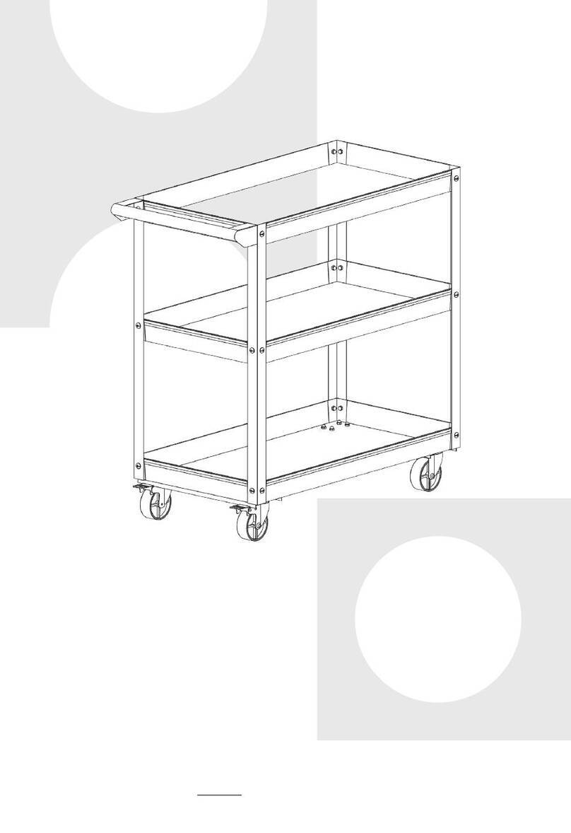
DIAGRAM FOR 2-SHELF SERVICE CARTS, Item# 143210, 196233, 143217
DIAGRAM FOR 3-SHELF SERVICE CARTS, Item# 143211, 143213

Page of 88
Parts List
No. Description Qty No. Description Qty No. Description Qty
1 Corner Cover 2 8 Beam 2 15 Washer 16
2 Corner Cover 2 9 Bracket of
Swivel Caster 2 16 Caster 16
3 Tray, (Item# 143210,
196233, 143217)
Tray, (Item# 143211,
143213)
2
3
10 Nut 4 17 Screw 16
4 Screw 8 11 Caster 4 18 Rod 1
5 Handle 1 12 Screw 4
7 Beam 2 13 Bracket of
Fixed Caster 2
For replacement parts and technical questions, please call 1-800-222-5381.
WARRANTY
90 days limited warranty
Distributed by
Northern Tool + Equipment Co., Inc.
Burnsville, Minnesota 55306-6936
Made in China
This manual suits for next models
4
Table of contents
Popular Outdoor Cart manuals by other brands

Carts Vermont
Carts Vermont 20 manual
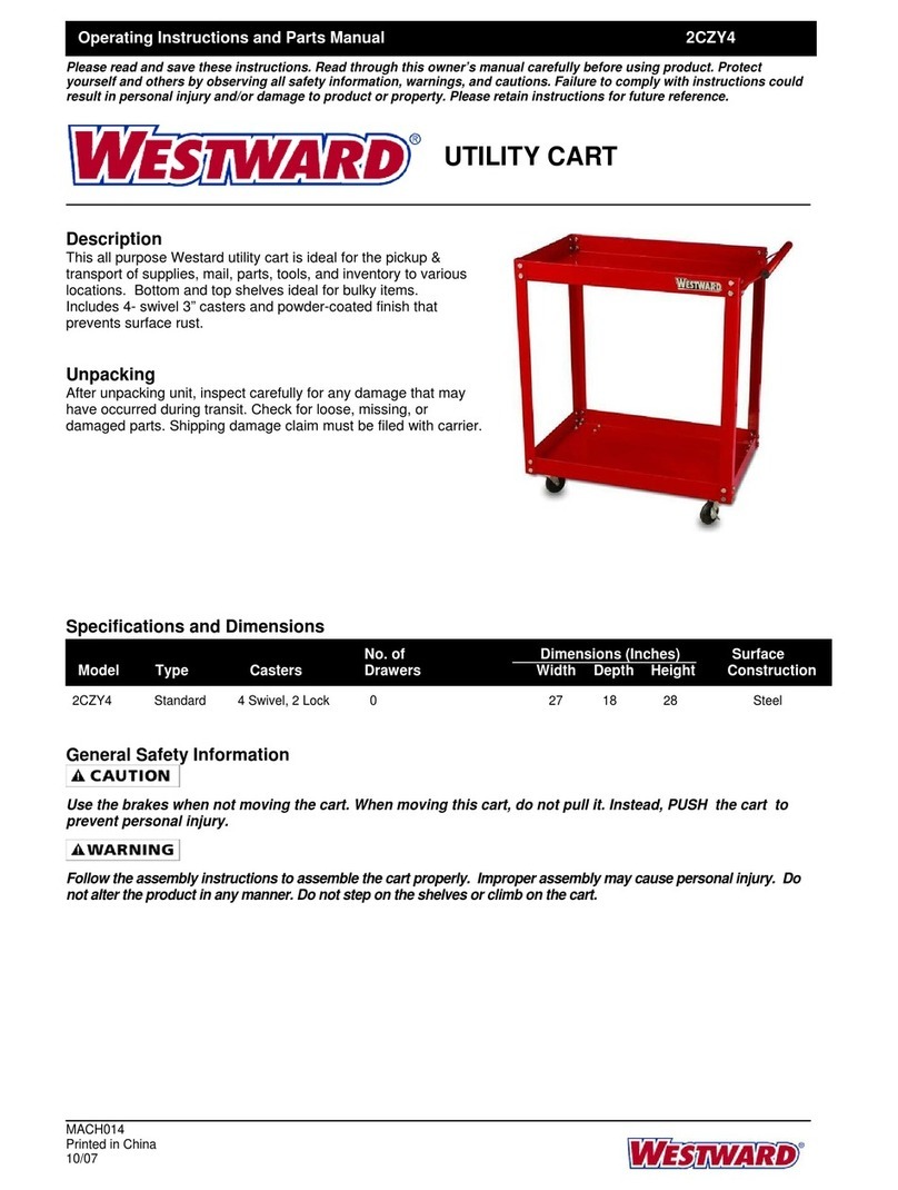
Westward
Westward 2CZY4 Operating instructions and parts manual
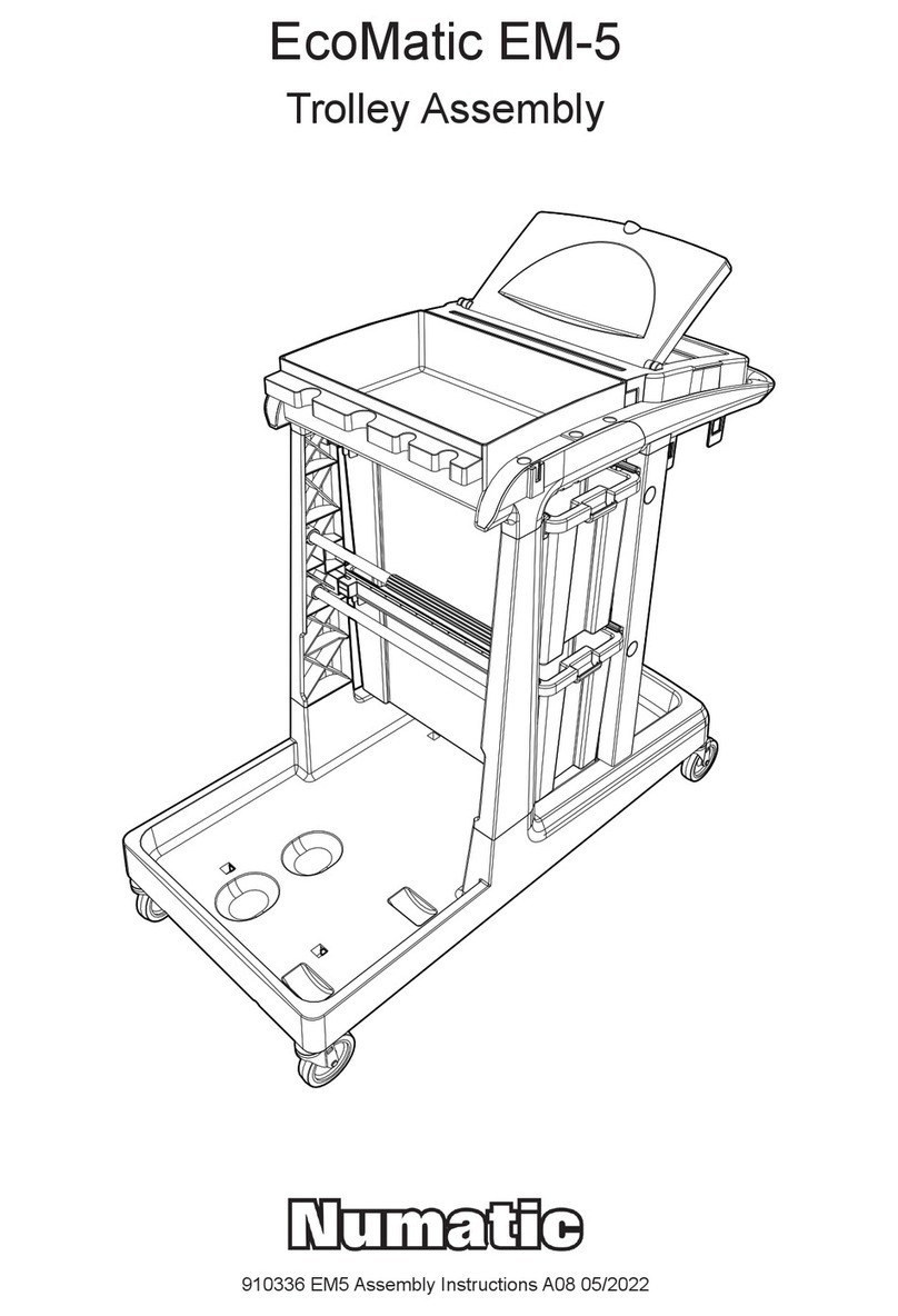
Numatic
Numatic EcoMatic EM-5 Assembly
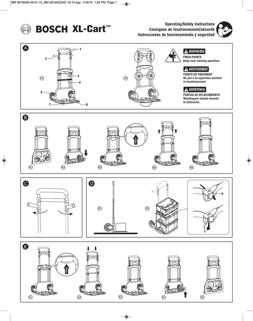
Bosch
Bosch XL-Cart Operating/safety instructions
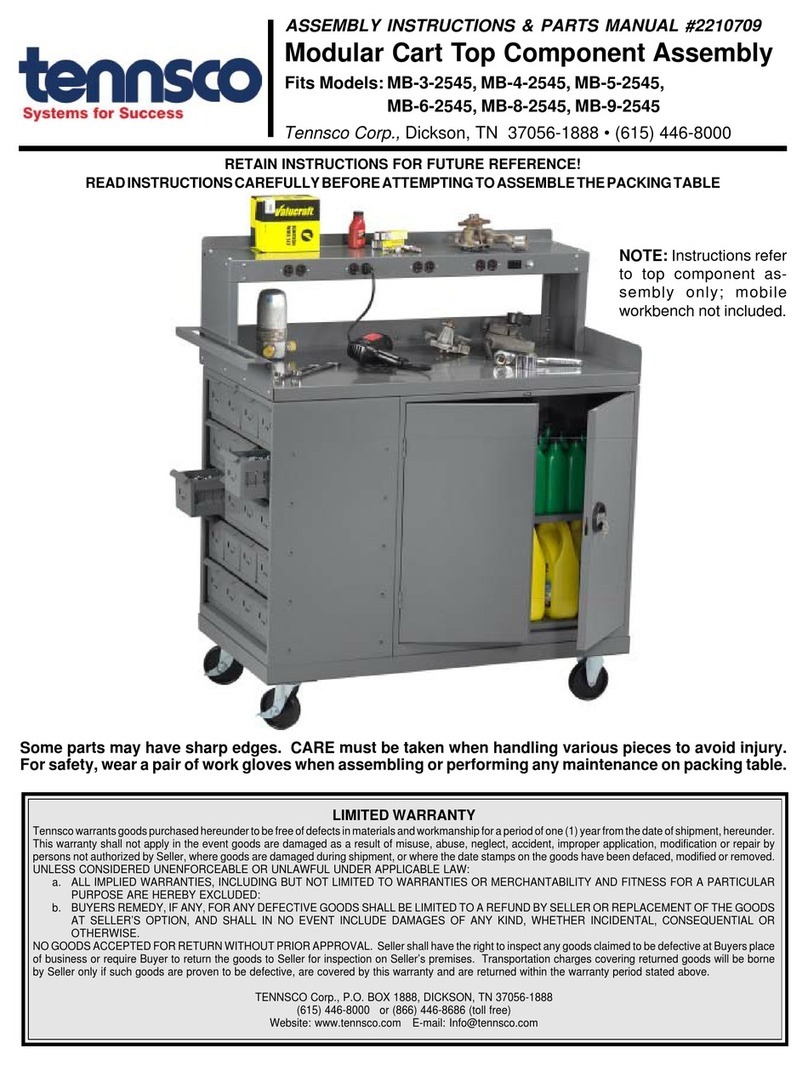
Tennsco
Tennsco Modular Cart Top Component Assembly Assembly Instructions/Parts Manual

Clam
Clam POLAR TRAILER HD MAX manual
