NOUVOLED VELA 250B User manual

VELA 250B
User Manual

Content
1. Caution and Installing
1.1Declaration......................................................................1
1.2 Maintainance .................................................................1
1.3 Product precautions.........................................................1
1.4 Product description..........................................................1
1.5 DMX connect .................................................................2
1.6 Fixture installing...............................................................2
2. LCD display .............................................................................4
2.1 Menu key.........................................................................4
2.2Menu...............................................................................5
2.2.1 Manual set.................................................................5
2.2.2 Set.............................................................................6
2.2.3 System .....................................................................7
3. Function DMX ...........................................................................8
3.1DMX chart .........................................................................8
4. Common error..........................................................................11

1.1 Notes and Installation Notes and Installation
Thank you for choosing our company's products! This product has good
performance and complete packaging when it leaves the factory. For your safe
and effective use of this product, please read this instruction manual carefully
and completely before you use this product. This manual contains important
information for installation and use. Please install and operate in accordance
with the requirements of the manual. At the same time, please keep this
manual properly for use at any time. Our company does not assume all
responsibility for damage to lamps or other performance due to personal
failure to follow the instructions during installation, use, and maintenance.
This manual is subject to technical changes without notice。
⚫Maintenance
⚫Please disconnect the power before performing maintenance。
⚫The lamp should be kept dry and avoid working in a humid environment。
⚫Intermittent use will effectively extend the life of the lamp。
⚫In order to obtain good ventilation and lighting effects, it is necessary to
clean the fan, fan net and lens frequently。
⚫Do not wipe the lamp housing with organic solvents such as alcohol to
avoid damage。
⚫Product precautions
⚫This lamp is for professional use only.
⚫Before operation, make sure that the power supply voltage matches the
power supply voltage required by the equipment.
⚫Do not place the product in a place that is easy to loose or shake.
⚫Stop using the lamp in time if the lamp is abnormal during use.
⚫In order to ensure the service life of the product, this product must not be
placed in a humid or leaking place, and it must not be used in an
environment where the temperature exceeds 60 degrees.
⚫When the bulb is in use, the power supply voltage should not change more
than ±10%. Too high voltage will shorten the life of the bulb, and too low
voltage will affect the light color of the bulb.
⚫After the power is cut off, it takes 20 minutes before the lamp is fully cooled
before being powered on again.
⚫The rotating parts of the lamp and the pasted accessories must be
checked regularly. If there is any looseness, the shaking should be
reinforced in time to prevent accidents.
⚫To ensure the normal use of this product, please read this manual
carefully。
⚫1.2 Product introduction
⚫Light source power: 250W;

⚫Voltage: AC 200V~240V/50~60Hz;
⚫Color wheel: each color wheel is composed of 13 color chips + white
light;
⚫Gobo plate: 14 pattern effects;
⚫540° pan, 270° tilt。
⚫Overheat protection;
⚫Control mode: DMX512/master-slave/auto;
⚫IP20 protection level
1.2 Signal line connection
The lamp is equipped with standard DMX input and output 3-pin or 5-pin XLR
sockets. Please use shielded twisted pair signal wire specially designed for
DMX 512; the signal wire is generally connected at a distance of 150 meters,
and DMX512 signal amplifier must be added for long distance signal
transmission.
Use a shielded twisted pair signal cable to connect from the DMX output port of
the controller to the DMX input port of the first device, and from the DMX
output port of the first device to the DMX input port of the second device, and
so on, Until all the lamps are connected, install a terminal plug on the output
3-pin jack of the last connected lamp of each connection. (Weld a 4/1W, 120Ω
resistor between the 2 and 3 pins of the 3-pin XLR plug).
Important note: the wires cannot touch each other or the metal shell。
➢Figure 1 Diagram of DMX signal line connection
Calculation method of lamp start address code:
The starting address code of the current fixture is equal to (the starting address
code of the previous fixture) + (the number of channels of the fixture)
1: The starting address code value of the first lamp is A001.
2: The number of basic channels of the controller should be greater than or
equal to the total number of channels used by the lamp.
3: Note: When using any controller, each lamp must have its own start address
code. If the start address code of the first lamp is set to A001, the number of
channels of the lamp is 16CH; then The start address code of the two lamps is
set to A017; the start address code of the third lamp is set to A033; and so on,
(this setting method also needs to be determined according to different

consoles)
1.2 Fixture Lamp installation
The lamps can be placed horizontally, hung diagonally and upside down.
Pay attention to the installation method when hanging diagonally and upside
down.
As shown in Figure 2, before locating the luminaire, ensure the stability of
the installation site. When reversing the hanging installation, you must ensure
that the luminaire does not fall down on the support frame. You need to use a
safety rope to pass through the support frame and the luminaire lift. Hand
assist hanging to ensure safety and prevent the lamp from falling and sliding.
When the lamps are installed and debugged, pedestrians are prohibited
from passing underneath. Regularly check whether the safety ropes are worn
and the hook screws are loose.
Our company will not bear any responsibility for all the consequences
caused by the falling of the lamp due to the unstable installation of the hanging.
Figure 2 Schematic diagram of upside down lamps

1.control panel
2.1 key instruction
Figure 3 Schematic diagram of panel keys
Take "Modify DMX Address Code" as an example to describe the
use of buttons:
1. If the current interface is not the main interface, press the "left"
key (one or more times) to return to the main interface
2. In the main interface, press "Up" or "Down" to select the
"Settings" button
3. Press the "OK" button to enter the "Settings" interface
4. In the "Settings" interface, press the "Up" or "Down" keys to
select "DMX Address"
5. Press "OK" to enter the editing state
6. Press "Up" or "Down" to modify the DMX address code

7. Press "OK" to exit the editing state
2.2.1 Manual
This interface is used to control the current lamp and automatically enter the host
state (do not receive DMX signals, send DMX signals to the bus to the slave).
The manual menu will display 16 channels or 20 channels according to the standard
16-channel or extended 20-channel mode set in the setting menu.
DMX channel
Description
1CH. Gobo wheel
0~255
Press the "OK" key to enter the editing state.
At this time, the hundreds place is selected,
press the "up" and "down" keys to change the
channel value. Press the "OK" key again to
select the ten digits for editing. Press the "OK"
key again to select the ones digit to edit.
Press again to exit the editing state
……
0~255
14CH.frost
0~255
16CH.reset
Press the "OK" button to see the confirmation
dialog box, press the "OK" button again to
enter the reset interface, and all motors are
reset
16CH.lamp control
on
Off
17CH.keep
0~255
Display when the channel mode is
"Extended CH20"
18CH. Color wheel speed
0~255
Display when the channel mode is
"Extended CH20"
19CH. dimmer-prism-frost
speed
0~255
Display when the channel mode is
"Extended CH20"
20CH. Gobo wheel speed
0~255
Display when the channel mode is
"Extended CH20"

Menu
Description
Mode
DMX
Slave state: receiving DMX signal from the console or
host
Auto run1
Master status: self-propelled and send DMX signal to
slave
Auto run 2
random
Voice
control
DMX address
1~512
Press the "OK" key to enter the editing state. At this time,
the hundreds digit is selected, press the "up" and "down"
keys to change the address code. Press the "OK" key again
to select the ten digits for editing. Press the "OK" key again
to select the ones digit to edit. Press again to exit the
editing state
Channel mode
16CH
Standard 16-channel mode, the 17th to 20th channels
are invalid
20CH
Extended 20 channel mode, the 17th to 20th channels
control the speed (see channel table)
X Reverse
off
on
Y Reverse
Off
On
XY exchange
Off
On
Exchange the channels of XY axis (including fine
adjustment)
XY Encoder
On
Use encoder (optocoupler) to judge out-of-step and
automatically correct position
Off
Correct position without using encoder (optocoupler)
DMX
Keep
Continue to run as it was
Clear 0
Motor returns to position and stops running
screen protector
On
Turn off the backlight after 30 seconds of idle
Off
Backlight always bright
Turn on the lamp
Off
Reset directly after power-on, without light bulb (you
need to use the menu or console to manually light the
bulb)
On
The bulb will light up automatically after power on, and it
will be reset only after the bulb lights up successfully
The color wheel
changes linearly
On
The color wheel changes linearly
Off
Non-linear change of color wheel, half color change
Restore default
settings
Press the "OK" button to see the confirmation dialog box,
press the "OK" button again to restore the default
settings

2.2.3 system
description
DIS
Display board software version
MT
Motor board software version
Reset
calibration
X axis calibration
After entering the sub-interface, you can
adjust the reset position of the X-axis, Y-axis
and other motors to compensate for the error
in the hardware installation. The adjustment
range is -128~+127, and +0 means no
adjustment.
Y axis calibration
Color calibration
Pattern calibration
Focus calibration
Dimming calibration
Prism 1 calibration
Prism 2 calibration
Atomization
calibration
Sensor
monitoring
X-axis Hall
0 when magnetism is detected, 1 otherwise
Y-axis Hall
0 when magnetism is detected, 1 otherwise
Color wheel hall
0 when magnetism is detected, 1 otherwise
Gobo Hall
0 when magnetism is detected, 1 otherwise
Focusing Hall
0 when magnetism is detected, 1 otherwise
Prism 1 Hall
0 when magnetism is detected, 1 otherwise
Prism 2 Hall
0 when magnetism is detected, 1 otherwise
X axis encoder disk
status
2 digits, each corresponding to a photoelectric
switch in the encoding disk
Y axis encoder disk
status
2 digits, each corresponding to a photoelectric
switch in the encoding disk
X axis encoder disc
step value
When walking in the positive direction, the step
value should increase, and when walking in the
reverse direction, the step value should decrease.
Every time you go to the same point, the value is
the same as normal
Y axis encoder disc
step value
When walking in the positive direction, the step
value should increase, and when walking in the
reverse direction, the step value should decrease.
Every time you go to the same point, the value is
the same as normal
System error
If the red ERR indicator is on, it means that the
lamp is running wrong, and you can enter the
sub-interface to view the details. After viewing,
you can press the "Clear" button to clear the error
record
DMX
monitor
Real-time monitoring of console signals

Mirror info
Description
MT board
connection
failed
The motor board does not respond. There is a problem with the
serial communication line connecting the display board and the
motor board, or there is a problem with the motor board.
X axis reset
failed
X-axis photoelectric switch, or X-axis motor or motor board has a
problem
Y axis reset
failed
Y-axis photoelectric switch, or Y-axis motor or motor board has a
problem
X axis Hall
error
X-axis Hall, or motor board problem
Y axis Hall
error
Y-axis Hall, or motor board problem
Color wheel
reset failed
The color wheel Hall, or the color wheel motor has a problem
Gobo reset
failed
Gobo Hall, or gobo motor has a problem
Focus reset
failed
There is a problem with the focus hall or the focus motor
Lamp control
failed
Failure to turn on or off the bulb, there is a problem with the lighter
or bulb
1. Function
3.1 DMX channel chart
ch
mode
16ch
20ch
1
Color wheel
Color wheel
2
Cut light/strobe
Cut light/strobe
3
Dimming
Dimming
4
Pattern plate
Pattern plate
5
Prism 1
Prism 1
6
Prism rotation 1
Prism rotation 1
7
Prism 2
Prism 2
8
Focus
Focus
9
X
X
10
X fine-tuning
X fine-tuning
11
Y
Y
12
Y fine-tuning
Y fine-tuning
13
XY speed
XY speed
14
Frost
Frost
15
Atomization & Colorful Mirror
Atomization & Colorful Mirror

16
Bulb control & reset
Bulb control & reset
17
Color wheel
no
18
Color wheel speed
19
Dimming-Prism-Atomization Speed
20
Gobo speed
Channel data:
CH
Function
Data
Effect
1
Color wheel
000-004
005 -009
010 - 014
015 - 019
020 - 024
025 - 029
030 - 034
035 - 039
040 - 044
045 - 049
050 - 054
055 - 059
060 - 064
065 - 069
070 - 074
075 - 079
080 - 084
085 - 089
090 - 094
095 - 099
100 -104
105 -109
110 -114
115 -119
120 -124
125 -129
130 -134
135 -139
140 -199
200 - 255
White light
White light + color 1
Color 1
Color 1+color 2
Color 2
Color 2+color 3
Color 3
Color 3+color 4
Color 4
Color 4+color 5
Color 5+color 6
Color 6
Color 6+color 7
Color 7
Color 7+color 8
Color 8
Color 8+color 9
Color 9
Color 9+color 10
Color 10
Color 10+color 11
Color 11
Color 11+color 12
Color 12
Color 12+color 13
Color 13
Color 13+white light
Positive flow (from fast to slow)
Reverse flow (from slow to fast)
2
Strobe
000-003
004-103
104-107
108-207
208-212
Shutter closed
Stroboscopic from slow to fast
Shutter open → (controlled by dimming channel)
Pulse strobe from slow to fast
Shutter open → (controlled by dimming channel)

213-251
252-255
Random strobe from slow to fast
Shutter open → (controlled by dimming channel)
3
Dimmer
000-255
4
Gobo wheel
000 - 004
005 - 009
010 - 014
015 - 019
020 - 024
025 - 029
030 - 034
035 - 039
040 - 044
045 - 049
050 - 054
055 - 059
060 - 064
065 - 069
070 - 074
075 - 079
080 - 084
085 - 089
090 - 094
095 - 099
100 - 104
105 - 109
110 - 114
115 - 119
120 - 124
125 - 129
130 - 134
135 - 139
140 - 200
201 - 255
Solid figure 1
Solid picture 2
Solid figure 3
Solid figure 4
Solid Figure 5
Solid figure 6
Solid figure 7
Solid figure 8
Solid figure 9
Solid figure 10
Solid figure 11
Solid figure 12
Solid figure 13
Solid figure 14
Fixed image 1 (from slow to fast)
Fixed image 2 (from slow to fast)
Fixed image 3(Slow to fast)
Fixed image 4 (from slow to fast)
Fixed image 5 (from slow to fast)
Fixed image 6 (from slow to fast)
Fixed image 7 (from slow to fast)
Fixed image 8 (from slow to fast)
Fixed image 9 (from slow to fast)
Fixed image10 (from slow to fast)
image11 (from slow to fast)
Fixed image 12 (from slow to fast)
Fixed image 13 (from slow to fast)
Fixed image 14 (from slow to fast)
Reverse flow (from fast to slow)
Positive flow (from slow to fast)
5
Prism 1
000-127
128-255
Prism 1 pops up
Prism 1 cut in
6
Prism
rotation
000-127
128-190
191-192
193-255
Prism angle adjustment
Reverse rotation (from fast to slow)
stop
Forward rotation (from slow to fast)
7
Prism 2
000-127
128-255
Prism 2 pops up
Prism 2 cut in
8
Prism 2
rotation
000-127
128-190
191-192
Prism angle adjustment
Reverse rotation (from fast to slow)
stop

193-255
Forward rotation (from slow to fast)
9
focusing
000-255
Pattern definition from far to near
10
X axis
000-255
Horizontal 540 degree scan
11
X-axis fine
adjustment
000-255
Level 1.2 degree fine adjustment
12
Y axis
000-255
Vertical 270 degree scan
13
Y-axis fine
adjustment
000-255
Vertical 1.2 degree fine adjustment
14
XY speed
000-255
Speed from fast to slow
15
Atomization &
Colorful Mirror
000-127
128-191
192-255
no
Colorful mirror cut in
Atomized slice cut in
16
Bulb control
000-099
100-105
200-205
250-255
Invalid area
Turn off the bulb
Light up the bulb
All motors reset
17
Keep
000-255
Speed from fast to slow
18
Color speed
19
Dimming-Pri
sm-Atomizati
on Speed
20
Gobo wheel
speed
2. Common faults
1. For some common faults, corresponding solutions are
proposed. Any problems that cannot be solved should be handled
by professionals. Before servicing the lamp, please disconnect the
power supply.
2. Light bulb does not light up
⚫Check whether the voltage matching the lamp is installed;
⚫Check whether the connection of the power supply of the lamp

or the control switch is bad;
⚫Check whether the power supply is insufficient;
⚫Check if the DMX512 controller has sent instructions。
3.After the lamp is reset normally, it does not accept the control
of the console
⚫Check whether the numerical start address and function options
of the lamp are correct;
⚫Check whether the connection of the communication control line
is correct, the communication line is too long or has been
interrupted;
⚫Check whether the control equipment is invalid, and check
whether the serially connected signal amplifier is invalid;
⚫Check whether the communication line is too long or other
equipment interferes with each other;
⚫Optimize wiring, shorten the length of control signal lines, and
separate high-voltage and low-voltage lines;
⚫Add signal amplifier;
⚫The signal line adopts high-quality shielded twisted pair;
⚫Connect a signal terminal resistor (120 ohm) at the end of the
lamp。

3. fixture cannot be started
⚫Check whether the power supply parameters are consistent with
the lamps;
⚫Check that the lamp has poor contact due to extrusion
deformation, internal parts vibration, moisture and other
reasons during long-distance transportation
⚫Or fall off.
⚫Please check whether the internal wire product connector of the
lamp is off or loose.
⚫Check whether the electronic components of the lamp (such as
electronic transformers, PCB boards, motor control boards, etc.)
are loose, short-circuited and burned out。
4.When working, the X-axis or Y-axis of the lamp does not work
properly
⚫Check one by one according to the previous step;
⚫Check whether the transmission belt corresponding to the X and
Y axis directions in the lamp is off or broken;
⚫Check whether the data feedback receiver (optocoupler)
corresponding to the X and Y directions in the lamp is damaged;
⚫Reboot and reset once
Popular Light Fixture manuals by other brands

Good Earth Lighting
Good Earth Lighting UC1045-WH1-18T81-G manual

Lightolier
Lightolier LSW Series specification

Westinghouse
Westinghouse Outdoor Lighting Fixture owner's manual

Triarch
Triarch Indoor Lighting 29585-GOLD Assembly instructions
GTV
GTV OA-MALEDPAN-00 manual
Kelvix
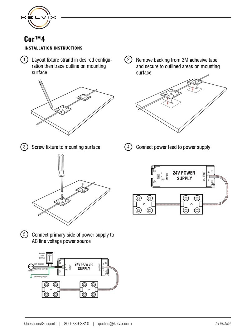
Kelvix Cor 4 installation instructions
