NOUVOLED PLANO 200 TW/CW User manual
PLANO 200 TW/CW
USER MANUAL
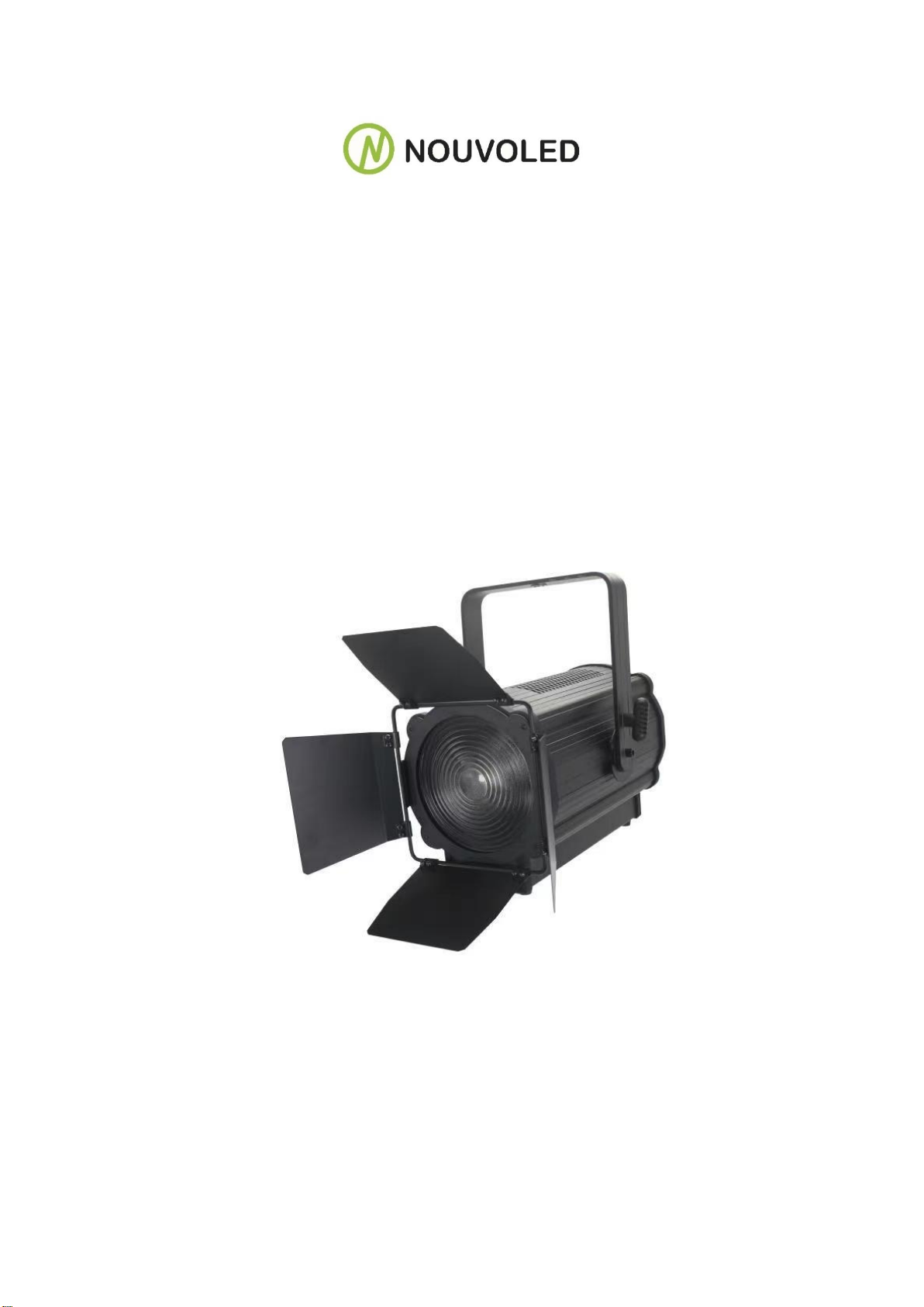
200W COB LED Fresnel spotlight

INSTRUCTION
Thank you for having chosen a led fresnel spot 200w. You will see you have a powerful and
versatile device.
Unpack your led studio spot 200w light
Delivery includes
Gobo frame: 1PC USER MANUAL: 1PC
DESCRIPTION OF THE DEVICE.
1.Profile
With the idea of energy saving and environment protection, the device use low power loss and
extremely high efficiency led. The device housing cover is made of used the new high strength
heat resistance engineering plastics, with beautiful shape and smooth lines. The designing and
manufacturing is in compliance with the IEC standard. The device is suitable in the large-scale
theatrical performance, the theater, the performance hall, the bar, nightclub and so on.
The product conforms to the international standard DMX512 agreement completely, the device
can be controlled in signal, and also be controlled in many units.
2.Specification
Lamp: 200w high power cob led
Power Supply: AC100V-250V, 50HZ/60HZ
Power consumption: 200w
2DMX control channels
Small volume, lightweight
High quality optical system
Different lens available (zoom 15°-50°)
N.W.:12kgs
4. Safety warning
①Warning:
◼ Every person involved with the installation, operation and maintenance of this device
has to be qualified.
◼User must follow the instructions of this manual.
◼Unqualified person cannot open the housing cover and operate the device, or the dealer
will not accept liability for any resulting defects or problems.
◼The device against rain and moisture.
②Warning notes:
◼ Power Supply: AC100V-250V, 50HZ/60HZ.
Make sure the power switch is off, the power plug, outlet and the earth
◼connection is in well condition before connecting the device with the mains.
◼Please use qualified power plug and outlet. Never connect the power cord of this device
with other electrical equipment.
◼During move and installation, make sure the device not crashed with metal parts and other
tough materials.
◼Always disconnect from the mains, when the device is on installation and dismantled.
◼The minimum distance between light-output the illuminated surface must be more than
50cm.
◼The device must only be installed on a non-flammable surface. In order to safeguard

sufficient ventilation, leave 50cm of free space around the device. Please note that heat-
sensitive objects may be deformed and damaged by the emitted heat.
◼During the operation the housing becomes hot! Don’t operate the device for 15 minutes
after switching off.
◼The maximum ambient temperature Ta=45°C must never be exceeded. The maximum
housing temperature Tb=80°C must never be exceeded.
◼For indoors use.
◼Replace any visible cracked protective shield, filters and lens.
◼The protective shield, filters and lens will require weekly cleaning as smoke “fluid tends to
building up residues, reducing the light” output very quickly.
INSTALLATION
1.Installation
◼When installation, keep the device far away the heat sensitive objects and explosives
sensitive objects, leave at least 50CM of free space around the device.
◼When the device put on horizontal place, the device must be placed directly on the place,
and device must be secured with a mounting holder.
◼When rigging the devices on the truss and the head face to the floor. Screw one clamp
each via a M12 screw and nut onto the mounting holder. Insert the quick-lock fasteners of
the first mounting holder into the respective holes on the bottom of the device. Tighten the
quick-lock fasteners fully clockwise. Install the second mounting holder. And the safety
rope must be used at same time.
◼Please use qualified safety-rope, which can hold at least 10 times the weight of the fixture.
You must only use safety-ropes with quick links with screw cap. Pull the safety-rope
through the hole on the bottom of the base and over the trussing system etc. Insert the
end in the quick link and tighten the fixation screw. A safety rope which already hold the
strain of a crash or which is defective must not be used again.
2.Dmx512 connection
◼ Please use xlr-xlr wires connect the dmx output the controller withe the dmx input of the
first device, and connect the dmx output of the first device with the dmx input of the second
device, always connect one output with the input of the next device until all devices are
connected.
◼Please use qualified xlr-xlr dmx cables.
3.Connection with mains
The person involved with the power connection must be qualified, and has the electrical
engineering certificate.
Connect the device to the mains with the power plug.
The earth has to be connected.
Power consumption 200w, input power supply AC100V-250V, 50HZ/60HZ.
4.Replace fuse
◼ Before replacing the fuse, unplug mains lead.
◼ Procedure:

Step1: Unscrew the fuse holder on the rear panel with a fitting screwdriver from the housing
(anti-clockwise).
Step2: Remove the old fuse from the fuse holder.
Step3: Install the new fuse in the fuse holder.
Step4: Replacing the fuse holder in the housing and fix it.
OPERATION
1.Description of the keys
◼MENU;
◼UP;
◼DOWN;
◼ENTER
2.Menu
No
Value
Function
1
A001
Dmx ,( 001—512)
2
1CH—2CH—3CH
DMX channels choose
3
CP99
Fade,( 01—99)
4
ST99
Strobe,( 01—99)
5
BE01- BE02
Two sound model choose
6
W255
Dimmer,( 000—255)
7
-ON- / -OFF
Screen open/close
3. Dmx channels
1. A2CH:
Channel
Value
Function
1
000-255
Master dimmer
2
000-255
Master strobe

2. B2CH:
3. 1CH
4.3CH
APPENDIX
Problem and solution
Caution:
◼ Unqualified person involved with installation, operation and maintenance of this device
is prohibited.
◼ If any above mentioned problem happened, or unknown problem happened, please
contact the manufactory or distributor for assistance.
Channel
Value
Function
1
000-255
Master dimmer
2
000-255
Function choose: 0—20empt;21—200
strobe and strobe speed ;201—240
sound control strobe ; 241—255 :
sound fast.
Channel
Value
Function
1
000-255
Master dimmer
Channel
Value
Function
1
000-255
Master dimmer
2
000-255
Master strobe
3
000-255
Fade 0—20empty;21--255 fade
speed
problem
reason
resolution
Device not work
No power
AC100V-250V, 50HZ/60HZ
Check the power connection,
and make sure device connect
the mains in well condition.
Check if switch is on
Check if the fuse is good
Led bub if off
Led bulb damaged
Led drive board damaged
Temperature
switch damaged
Replacing led bulb
Replacing led driver board
Replacing temperature switch
Fans not work
Fans damaged
Replacing fans
Table of contents
Other NOUVOLED Spotlight manuals


Popular Spotlight manuals by other brands

M-Elec
M-Elec Apex Series Product information

fox fury
fox fury TacSwan YUNEEC 700-YPS product manual

Esseci
Esseci HALL LED DEEP Assembly instructions

IMG STAGE LINE
IMG STAGE LINE PARC-100E/WS Instruction manuals

Delta Light
Delta Light M20-MIDISPY DIM5 installation instructions

LIVARNO LUX
LIVARNO LUX LED SOLAR SPOTLIGHT Assembly, operating and safety instructions


